2006 SUZUKI SWIFT 1.1
[x] Cancel search: 1.1Page 304 of 1496

Downloaded from www.Manualslib.com manuals search engine 1D-19 Engine Mechanical:
24) Before removing engine with transaxle from engine compartment, recheck to make sure all hoses,
electric wires and cables are disconnected from
engine and transaxle.
25) Lower engine with transaxle from engine compartment.
CAUTION!
Before lowering engine, to avoid damage to
A/C compressor and clutch operating
cylinder, make clearance by rising them. Be
sure not to damage suspended A/C
compressor and clutch operating cylinder.
26) Disconnect transaxle from engine, referring to “Manual Transaxle Unit Dismounting and
Remounting in Section 5B” or “Automatic Transaxle
Unit Dismounting and Re mounting in Section 5A”.
27) For M/T model, remove clutch cover and clutch disk referring to “Clutch Cover, Clutch Disc and Flywheel
Removal and Installa tion in Section 5C”.
Installation 1) For M/T model, install clutch cover and clutch disk referring to “Clutch Cover, Clutch Disc and Flywheel
Removal and Installa tion in Section 5C”.
2) Connect transaxle to engine referring to “Manual Transaxle Unit Dismounting and Remounting in
Section 5B” or “Automatic Transaxle Unit
Dismounting and Remounting in Section 5A”.
3) Lift engine and transaxle into engine compartment with jack.
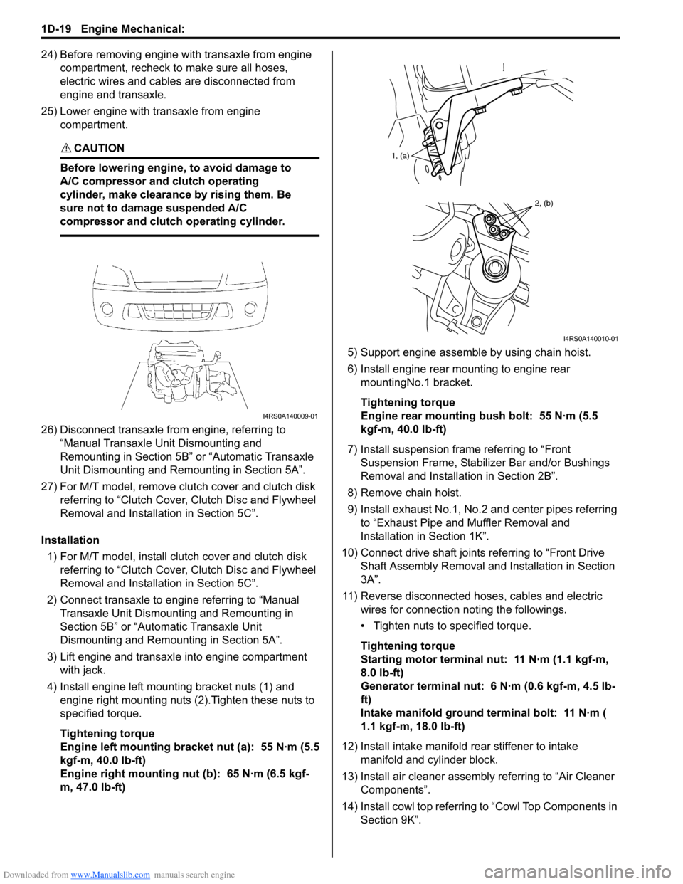
4) Install engine left mounting bracket nuts (1) and engine right mounting nuts (2).Tighten these nuts to
specified torque.
Tightening torque
Engine left mounting bracket nut (a): 55 N·m (5.5
kgf-m, 40.0 lb-ft)
Engine right mounting nut (b): 65 N·m (6.5 kgf-
m, 47.0 lb-ft) 5) Support engine assemble by using chain hoist.
6) Install engine rear mounting to engine rear
mountingNo.1 bracket.
Tightening torque
Engine rear mounting bush bolt: 55 N·m (5.5
kgf-m, 40.0 lb-ft)
7) Install suspension frame referring to “Front Suspension Frame, Stabiliz er Bar and/or Bushings
Removal and Installati on in Section 2B”.
8) Remove chain hoist.
9) Install exhaust No.1, No.2 and center pipes referring to “Exhaust Pipe and Muffler Removal and
Installation in Section 1K”.
10) Connect drive shaft joints referring to “Front Drive Shaft Assembly Removal and Installation in Section
3A”.
11) Reverse disconnected hoses, cables and electric wires for connection noting the followings.
• Tighten nuts to specified torque.
Tightening torque
Starting motor terminal nut: 11 N·m (1.1 kgf-m,
8.0 lb-ft)
Generator terminal nut: 6 N·m (0.6 kgf-m, 4.5 lb-
ft)
Intake manifold ground terminal bolt: 11 N·m (
1.1 kgf-m, 18.0 lb-ft)
12) Install intake manifold rear stiffener to intake
manifold and cylinder block.
13) Install air cleaner assembly referring to “Air Cleaner Components”.
14) Install cowl top referring to “Cowl Top Components in
Section 9K”.
I4RS0A140009-01
1, (a)
2, (b)
I4RS0A140010-01
Page 305 of 1496

Downloaded from www.Manualslib.com manuals search engine Engine Mechanical: 1D-20
15) Install A/C compressor to its bracket (if equipped) referring to “Compressor Assembly Removal and
Installation in Section 7B” or “Compressor Assembly
Removal and Installa tion in Section 7B”.
16) Adjust A/C compressor belt tension (if equipped) referring to “Compressor Drive Belt Inspection and
Adjustment in Section 7B” or “Compressor Drive Belt
Inspection and Adjustment in Section 7B”.
17) Check to ensure that a ll removed parts are back in
place.
Reinstall any necessary parts which have not been
reinstalled.
18) Refill cooling system with coolant referring to “Cooling System Flush and Refill in Section 1F”. 19) Refill engine with engine oil
referring to “Engine Oil
and Filter Change in Section 0B”.
20) Refill transaxle with transa xle oil referring to“Manual
Transaxle Oil Change in Section 5B” or “A/T Fluid
Change in Section 5A”.
21) Install battery and tray.
22) Connect positive and negative cable at battery.
23) Install engine hood and connect windshield washer hose.
24) Verify that there is no fu el leakage, coolant leakage,
oil leakage and exhaust gas leakage at each
connection.
Timing Chain Cover ComponentsS7RS0B1406012
I6RS0C140015-02
1. Crankshaft pulley bolt 13. Oil gallery pipe No.2 bolt
2. Crankshaft pulley 14. Oil gallery pipe No.3
3. Oil seal : Apply engine oil to oil seal lip. 15. Oil gallery pipe No.3 bolt
4. Timing chain cover : Apply sealant 99000-31140 to the mating surface of cylinder and cylinder head.
: Apply sealant 99000-31260 to the mating surface of timing chain cover referring to the
figure of Step 4) of “Installation” under “Timing Chain Cover Removal and Installation”. 16. O-ring
: Apply engine oil.
5. Pin 17. Oil control valve
6. Cap bolt 18. Oil control valve mounting nut
7. Timing chain cover mounting bolts 19. Cap
8. Timing chain cover mounting nut : 11 N ⋅m (1.1 kgf-m, 8.0 lb-ft)
9. Oil gallery pipe No.1 :25 N⋅m (2.5 kgf-m, 18.0 lb-ft)
Page 308 of 1496

Downloaded from www.Manualslib.com manuals search engine 1D-23 Engine Mechanical:
8) Install new O-ring (1) to oil gallery pipes No.2 (2) and
No.3 (3).
9) Install oil gallery pipes No.2 and No.3 to cylinder
head (4) and timing chain cover (5).
Tighten bolts to specified torque.
Tightening torque
Oil gallery pipe No.2 and No.3 bolt (a): 11 N·m (
1.1 kgf-m, 8.0 lb-ft)
10) Install water pump pulley. 11) Install cylinder head cover referring to “Cylinder Head Cover Removal and Installation”.
12) Install oil pan referring to “Oil Pan and Oil Pump
Strainer Removal and Installation in Section 1E”.
13) Install crankshaft pulley (1). Tighten bolt (2) to specified torque. To lock crankshaft pulley, use
special tool with it as shown in figure.
Special tool
(A): 09917–68221
Tightening torque
Crankshaft pulley bolt (a): 150 N·m (15.0 kgf-m,
108.5 lb-ft)
14) Install engine assembly to vehicle referring to “Engine Assembly Removal and Installation”.
Timing Chain Cover InspectionS7RS0B1406014
Oil Seal
Check oil seal lip for fault or other damage. Replace as
necessary. Timing Chain Cover
Inspect strainer (1) of oil passage for driving intake cam
timing sprocket assembly (VVT actuator).
If clog or foreign matter exists, clean strainer.
Oil Control Valve Removal and InstallationS7RS0B1406015
Removal
Remove oil gallery pipe No.1
(1) and oil control valve (2)
from timing chain cover (3).
Installation
1) Install new O-ring (4) to oil control valve.
2) Install oil control valve to timing chain cover. Tighten nuts to specification.
Tightening torque
Oil control valve mounting nut (a): 11 N·m (1.1
kgf-m, 8.0 lb-ft)
3) Install oil gallery pipe No .1 with new copper washers
(5) to timing chain cover.
Tighten bolts to specification.
Tightening torque
Oil gallery pipe No.1 bolt (b): 30 N·m (3.0 kgf-m,
21.5 lb-ft)
(a)
(a) 1
2
3
4
5
I3RH0B140027-01
I2RH0B140056-01
1
I3RH0B140028-01
1
5
(b) 3
(a)
2 4
5
I3RM0A140027-01
Page 309 of 1496

Downloaded from www.Manualslib.com manuals search engine Engine Mechanical: 1D-24
Oil Control Valve InspectionS7RS0B1406016
Oil Control Valve1) Inspect strainer (1) and mating surface (2) of oil control valve for clog or damage. Clean oil control
valve if clog or foreign matter is present on strainer
or mating surface of oil control valve.
Replace oil control valve if its mating surface is
damaged.
2) Check resistance between terminals of oil control
valve.
Oil control valve resistance
6.7 – 7.7 Ω (at 20 °C (68 °F)) Oil Gallery Pipe
Inspect oil gallery pipes No
.1, No.2 (2) and No.3 (3).
Replace if crack, deformation or clog exists.
Timing Chain and Chain Tensioner ComponentsS7RS0B1406017
1
2
I3RM0A140028-01
1
3
2
I3RH0B140030-01
I4RS0A140012-04
1. Crankshaft timing sprocket 5. Timing chain tensioner adjuster assembly 9. Spacer
2. Timing chain : Apply engine oil. 6. Chain tensioner adjuster mounting bolt
: 25 N⋅m (2.5 kgf-m, 18.0 lb-ft)
3. Timing chain No.1 guide : Apply engine oil to sliding surface. 7. Timing chain tensioner bolt
: 11 N⋅m (1.1 kgf-m, 8.0 lb-ft)
4. Timing chain tensioner : Apply engine oil to sliding surface. 8. Timing chain No.1 guide bolt
: 9 N⋅m (0.9 kgf-m, 6.5 lb-ft)
Page 312 of 1496

Downloaded from www.Manualslib.com manuals search engine 1D-27 Engine Mechanical:
8) Screw in plunger (1) by turning body (2) in arrow direction and install a reta iner (3) (wire) to hold
plunger in place.
9) Install timing chain tensioner adjuster assembly (1) with a retainer (2).
Tighten adjuster bolts to specified torque and then
remove a retainer from chain tensioner adjuster
assembly.
Tightening torque
Timing chain tensioner adjuster bolt (a): 11 N·m
(1.1 kgf-m, 8.0 lb-ft)
10) Apply engine oil to timing chain, and then turn crankshaft clockwise by 2 revolutions and check that
match marks (1) are at the following specific
positions.
• Intake and exhaust camshaft timing sprockets makes (1) are in match with notches (2) on
cylinder head.
• Crankshaft sprocket key (3) is in match with notch of cylinder block (4).
• Crankshaft sprocket key (3) is on upside of crankshaft as shown in figure. 11) Install timing chain cover referring to “Timing Chain
Cover Removal and Installation”.
Timing Chain and Chain Tensioner InspectionS7RS0B1406019
Timing Chain No.1 Guide
Check shoe (1) for wear or damage.
Timing Chain Tensioner
Check shoe (1) for wear or damage.
I2RH0B140065-01
I2RH0B140066-01
1
1
2
3 4
I6RS0C140017-01
I2RH0B140068-01
I2RH0B140069-01
Page 313 of 1496

Downloaded from www.Manualslib.com manuals search engine Engine Mechanical: 1D-28
Crankshaft Timing Sprocket
Check teeth of sprocket for wear or damage.Timing Chain
Check timing chain for wear or damage.
Timing Chain Tensioner Adjuster
Check that tooth surface (1) are free from damage.
Camshaft, Tappet and Shim ComponentsS7RS0B1406020
I2RH0B140070-01
I2RH01140077-01
I2RH0B140071-01
I6RS0C140018-01
1. Intake camshaft
5. Shim
: Shim No. on it faces tappet side. 9. Camshaft bearing
: Install a bearing half with some holes to upper side of intake
camshaft No.1 bearing.
2. Intake camshaft sprocket assembly 6. Tappet : 60 N⋅m (6.0 kgf-m, 43.5 lb-ft)
3. Intake camshaft sprocket bolt 7. Camshaft housing : Tighten 5 N⋅m (0.5 kgf-m, 4.0 lb-ft) and 11 N ⋅m (1.1 kgf-m,
8.0 lb-ft) by the specified procedure.
4. Exhaust camshaft 8. Camshaft housing bolt : Apply engine oil to sliding surface of each part.
Page 316 of 1496

Downloaded from www.Manualslib.com manuals search engine 1D-31 Engine Mechanical:
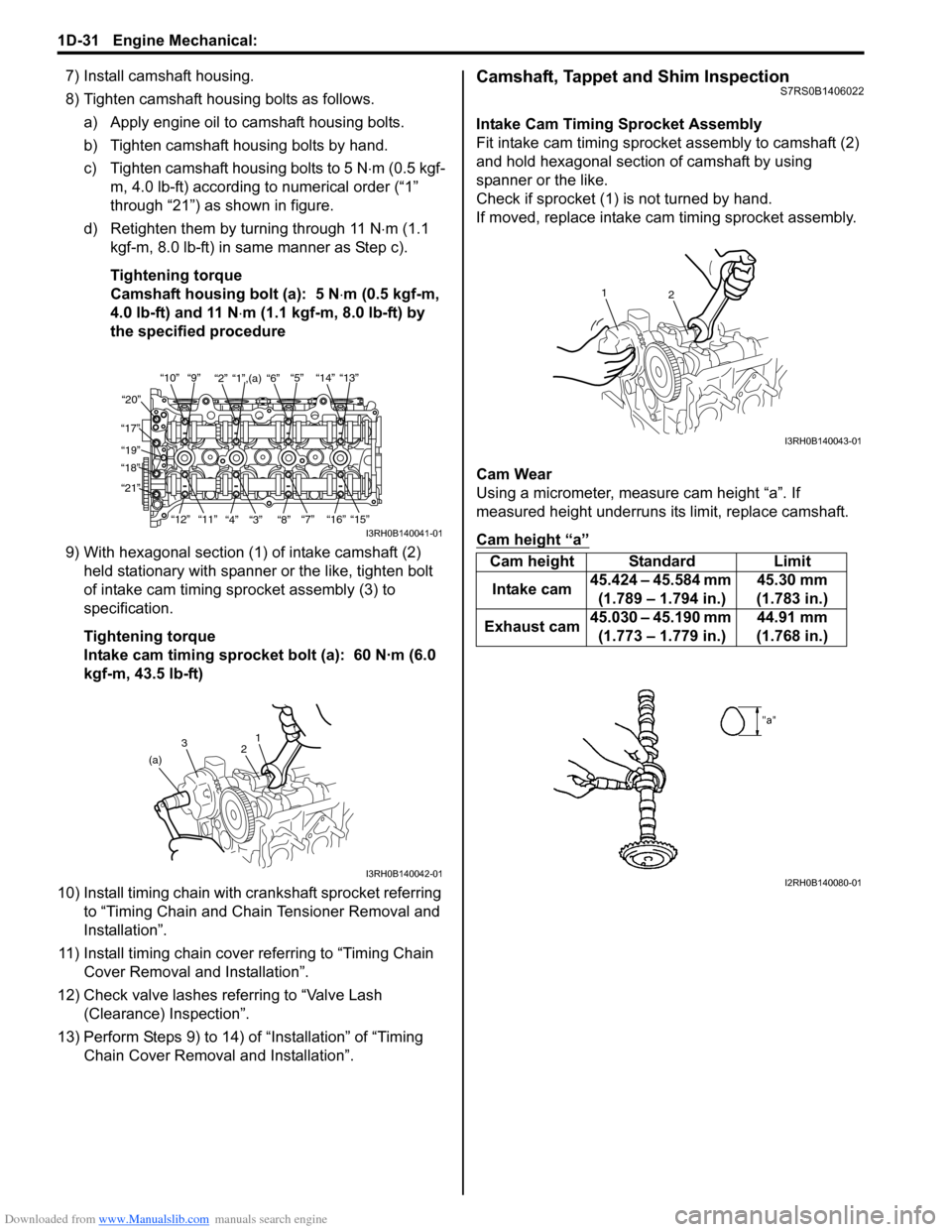
7) Install camshaft housing.
8) Tighten camshaft housing bolts as follows.a) Apply engine oil to camshaft housing bolts.
b) Tighten camshaft housing bolts by hand.
c) Tighten camshaft housing bolts to 5 N ⋅m (0.5 kgf-
m, 4.0 lb-ft) according to numerical order (“1”
through “21”) as shown in figure.
d) Retighten them by turning through 11 N⋅ m (1.1
kgf-m, 8.0 lb-ft) in same manner as Step c).
Tightening torque
Camshaft housing bolt (a): 5 N ⋅m (0.5 kgf-m,
4.0 lb-ft) and 11 N ⋅m (1.1 kgf-m, 8.0 lb-ft) by
the specified procedure
9) With hexagonal section (1) of intake camshaft (2) held stationary with spanner or the like, tighten bolt
of intake cam timing sp rocket assembly (3) to
specification.
Tightening torque
Intake cam timing sprocket bolt (a): 60 N·m (6.0
kgf-m, 43.5 lb-ft)
10) Install timing chain with cr ankshaft sprocket referring
to “Timing Chain and Chain Tensioner Removal and
Installation”.
11) Install timing chain cover referring to “Timing Chain Cover Removal and Installation”.
12) Check valve lashes referring to “Valve Lash (Clearance) Inspection”.
13) Perform Steps 9) to 14) of “Installation” of “Timing Chain Cover Removal and Installation”.Camshaft, Tappet and Shim InspectionS7RS0B1406022
Intake Cam Timing Sprocket Assembly
Fit intake cam timing sprocket assembly to camshaft (2)
and hold hexagonal section of camshaft by using
spanner or the like.
Check if sprocket (1) is not turned by hand.
If moved, replace intake ca m timing sprocket assembly.
Cam Wear
Using a micrometer, measure cam height “a”. If
measured height underruns its limit, replace camshaft.
Cam height “a”
“10”“9” “2” “1”,(a) “6” “5” “14” “13”
“20”
“17” “19”
“18”
“21”
“12”“11”
“4” “3” “8” “7” “16” “15”
I3RH0B140041-01
1
2
3
(a)
I3RH0B140042-01
Cam height Standard Limit
Intake cam 45.424 – 45.584 mm
(1.789 – 1.794 in.) 45.30 mm
(1.783 in.)
Exhaust cam 45.030 – 45.190 mm
(1.773 – 1.779 in.) 44.91 mm
(1.768 in.)
2
1
I3RH0B140043-01
I2RH0B140080-01
Page 317 of 1496

Downloaded from www.Manualslib.com manuals search engine Engine Mechanical: 1D-32
Camshaft Runout
Set camshaft between two “V” blocks, and measure its
runout by using a dial gauge.
If measured runout exceeds limit, replace camshaft.
Camshaft runout limit
0.10 mm (0.0039 in.)
Camshaft Journal Wear
Check camshaft journals and camshaft housings for
pitting, scratches, wear or damage.
If any malcondition is found, replace camshaft or cylinder
head with housing. Never re place cylinder head without
replacing housings.
Check clearance by using ga uging plastic. Checking
procedure is as follows.
1) Clean housings and camshaft journals.
2) Remove all tappets with shims.
3) Install camshafts to cylinder head.
4) Place a piece of gauging plastic to full width of
journal of camshaft (parallel to camshaft).
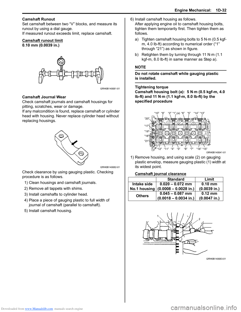
5) Install camshaft housing. 6) Install camshaft housing as follows.
After applying engine oil to camshaft housing bolts,
tighten them temporarily first. Then tighten them as
follows.
a) Tighten camshaft housing bolts to 5 N ⋅m (0.5 kgf-
m, 4.0 lb-ft) according to numerical order (“1”
through “21”) as shown in figure.
b) Retighten them by turning through 11 N ⋅m (1.1
kgf-m, 8.0 lb-ft) in same manner as Step a).
NOTE
Do not rotate camshaft while gauging plastic
is installed.
Tightening torque
Camshaft housing bolt (a): 5 N ⋅m (0.5 kgf-m, 4.0
lb-ft) and 11 N ⋅m (1.1 kgf-m, 8.0 lb-ft) by the
specified procedure
1) Remove housing, and using scale (2) on gauging plastic envelop, measure gauging plastic (1) width at
its widest point.
Camshaft journal clearanceI2RH0B140081-01
I2RH0B140082-01
Standard Limit
Intake side
No.1 housing 0.020 – 0.072 mm
(0.0008 – 0.0028 in.) 0.10 mm
(0.0039 in.)
Others 0.045 – 0.087 mm
(0.0018 – 0.0034 in.) 0.12 mm
(0.0047 in.)
“10”“9” “2” “1”,(a) “6” “5” “14” “13”
“20”
“17” “19”
“18”
“21”
“12”“11”
“4” “3” “8” “7” “16” “15”
I3RH0B140041-01
I2RH0B140083-01