2006 SUZUKI SWIFT 1.1
[x] Cancel search: 1.1Page 390 of 1496
Downloaded from www.Manualslib.com manuals search engine 1G-15 Fuel System:
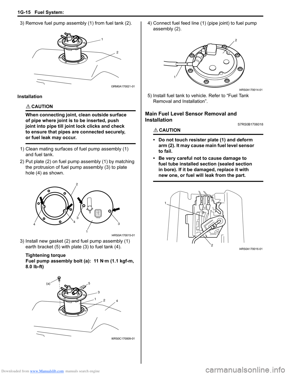
3) Remove fuel pump assembly (1) from fuel tank (2).
Installation
CAUTION!
When connecting joint, clean outside surface
of pipe where joint is to be inserted, push
joint into pipe till jo int lock clicks and check
to ensure that pipes are connected securely,
or fuel leak may occur.
1) Clean mating surfaces of fuel pump assembly (1) and fuel tank.
2) Put plate (2) on fuel pump assembly (1) by matching the protrusion of fuel pump assembly (3) to plate
hole (4) as shown.
3) Install new gasket (2) and fuel pump assembly (1) earth bracket (5) with plate (3) to fuel tank (4).
Tightening torque
Fuel pump assembly bolt (a): 11 N·m (1.1 kgf-m,
8.0 lb-ft) 4) Connect fuel feed line (1) (pipe joint) to fuel pump
assembly (2).
5) Install fuel tank to vehi cle. Refer to “Fuel Tank
Removal and Installation”.
Main Fuel Level Sensor Removal and
Installation
S7RS0B1706018
CAUTION!
• Do not touch resister plate (1) and deform arm (2). It may cause main fuel level sensor
to fail.
• Be very careful not to cause damage to fuel tube installed section (sealed section
in bore). If it be damaged, replace it with
new one, or fuel will leak from the part.
1
2
I3RM0A170021-01
3
1
3
2
44
I4RS0A170015-01
3
1 2
(a)
4
5
I6RS0C170009-01
2
1
I4RS0A170014-01
1
2I4RS0A170016-01
Page 391 of 1496

Downloaded from www.Manualslib.com manuals search engine Fuel System: 1G-16
Removal1) Remove fuel pump assembly from fuel tank referring to “Fuel Pump Assembly Removal and Installation”.
2) Disconnect main fuel level sensor connector (3).
3) With pressing snap-fit part (2), remove main fuel level sensor (1) by sliding it in the arrow direction as
shown in figure.
Installation
Reverse removal procedure for installation.Fuel Pump InspectionS7RS0B1706019
• Check fuel pump assembly for damage.
• Check fuel suction filter for evidence of dirt and contamination. If present, replace or clean and check
for presence of dirt in fuel tank.
• For electrical circuit, refer to “Fuel Pressure Check in Section 1A”.
• For inspection of main fuel level sensor (1), refer to “Fuel Level Sensor Inspection in Section 9C”.
Specifications
Tightening Torque SpecificationsS7RS0B1707001
NOTE
The specified tightening torque is also described in the following.
“Fuel System Components”
“Fuel Hose Disconnecting and Reconnecting”
Reference:
For the tightening torque of fastener not specified in this section, refer to “Fasteners Information in Section 0A”.
1
21
3
I5RS0D170006-031
I5RS0D170008-01
Fastening part
Tightening torque
Note
N ⋅mkgf-mlb-ft
Fuel delivery pipe bolt 25 2.5 18.0 �)
Ground wire bolt 11 1.1 8.0 �)
Fuel tank bolt 45 4.5 33.0 �)
Fuel filler hose clamp 2 0.2 1.5 �)
Fuel pump assembly bolt 11 1.1 8.0 �)
Page 399 of 1496
Downloaded from www.Manualslib.com manuals search engine Ignition System: 1H-7
High-Tension Cord InspectionS7RS0B1806002
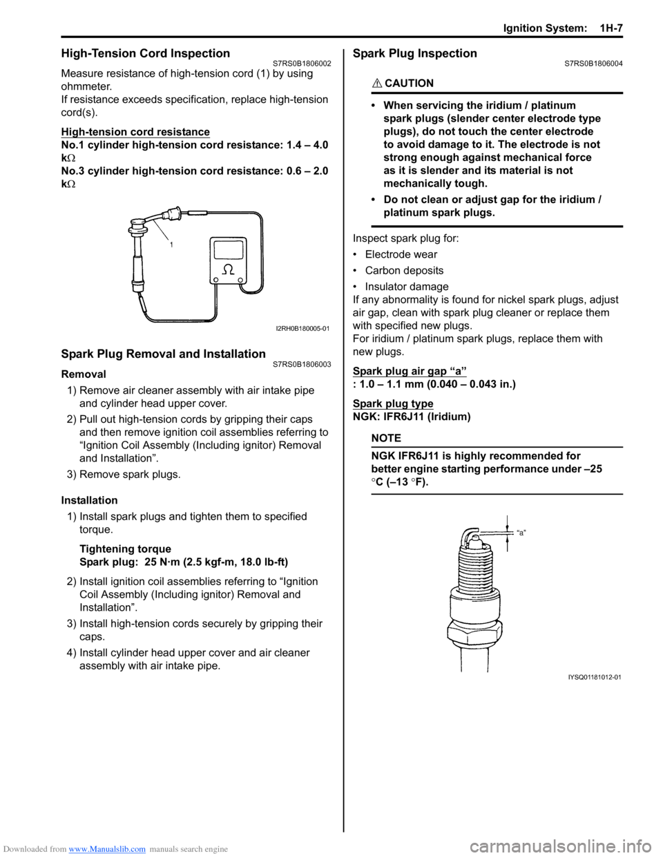
Measure resistance of high-tension cord (1) by using
ohmmeter.
If resistance exceeds specification, replace high-tension
cord(s).
High-tension cord resistance
No.1 cylinder high-tension cord resistance: 1.4 – 4.0
k Ω
No.3 cylinder high-tension cord resistance: 0.6 – 2.0
k Ω
Spark Plug Removal and InstallationS7RS0B1806003
Removal
1) Remove air cleaner assembly with air intake pipe and cylinder head upper cover.
2) Pull out high-tension cords by gripping their caps and then remove ignition coil assemblies referring to
“Ignition Coil Assembly (Inc luding ignitor) Removal
and Installation”.
3) Remove spark plugs.
Installation 1) Install spark plugs and tighten them to specified torque.
Tightening torque
Spark plug: 25 N·m (2.5 kgf-m, 18.0 lb-ft)
2) Install ignition coil assemblies referring to “Ignition Coil Assembly (Including ignitor) Removal and
Installation”.
3) Install high-tension cords securely by gripping their caps.
4) Install cylinder head upper cover and air cleaner assembly with air intake pipe.
Spark Plug InspectionS7RS0B1806004
CAUTION!
• When servicing the iridium / platinum
spark plugs (slender center electrode type
plugs), do not touch the center electrode
to avoid damage to it. The electrode is not
strong enough against mechanical force
as it is slender and its material is not
mechanically tough.
• Do not clean or adjust gap for the iridium / platinum spark plugs.
Inspect spark plug for:
• Electrode wear
• Carbon deposits
• Insulator damage
If any abnormality is found for nickel spark plugs, adjust
air gap, clean with spark plug cleaner or replace them
with specified new plugs.
For iridium / platinum spark plugs, replace them with
new plugs.
Spark plug air gap
“a”
: 1.0 – 1.1 mm (0.040 – 0.043 in.)
Spark plug type
NGK: IFR6J11 (Iridium)
NOTE
NGK IFR6J11 is highly recommended for
better engine starting performance under –25
°C (–13 °F).
I2RH0B180005-01
IYSQ01181012-01
Page 408 of 1496
Downloaded from www.Manualslib.com manuals search engine 1I-7 Starting System:
Spring
Inspect brush springs for wear, damage or other
abnormal conditions. Replace if necessary.
Brush spring tension
Standard: 2.2 kg (4.85 lb)
Limit: 0.6 kg (1.33 lb)
Brush Holder
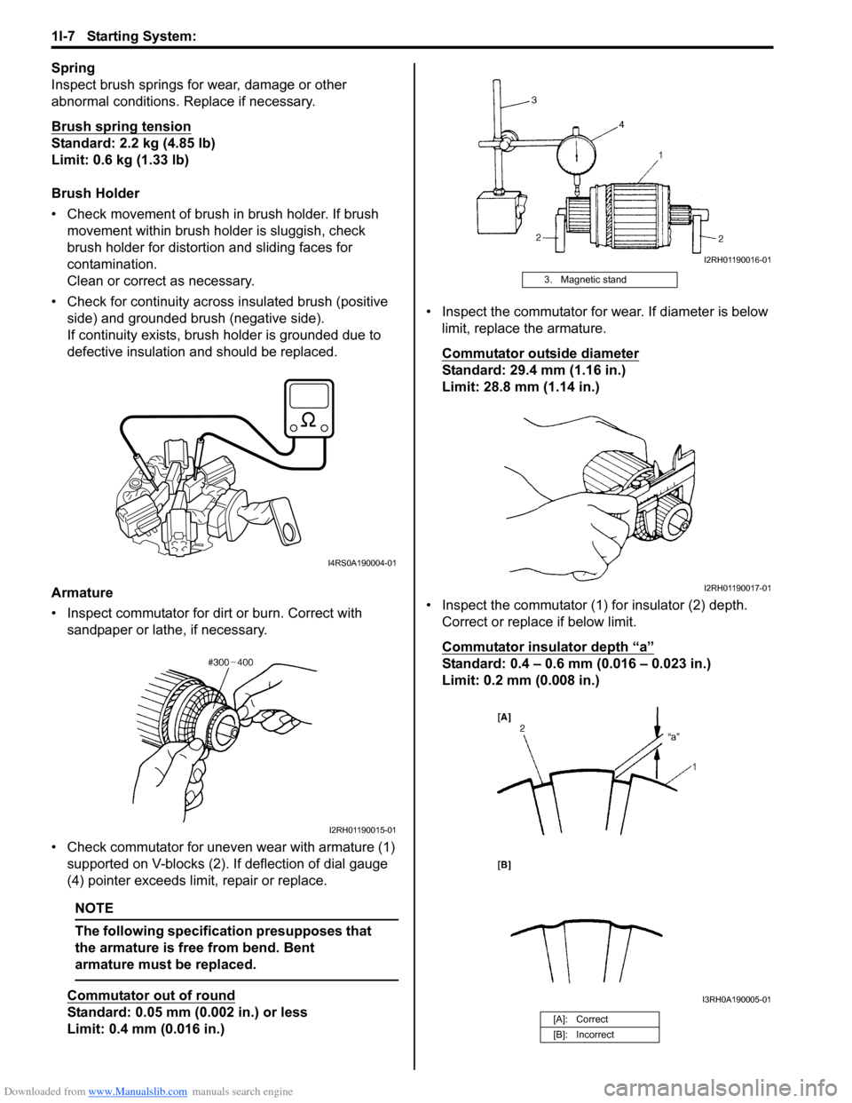
• Check movement of brush in brush holder. If brush movement within brush holder is sluggish, check
brush holder for distortion and sliding faces for
contamination.
Clean or correct as necessary.
• Check for continuity across insulated brush (positive side) and grounded brush (negative side).
If continuity exists, brus h holder is grounded due to
defective insulation and should be replaced.
Armature
• Inspect commutator for dirt or burn. Correct with sandpaper or lathe, if necessary.
• Check commutator for uneven wear with armature (1) supported on V-blocks (2). If deflection of dial gauge
(4) pointer exceeds limit, repair or replace.
NOTE
The following specification presupposes that
the armature is free from bend. Bent
armature must be replaced.
Commutator out of round
Standard: 0.05 mm (0.002 in.) or less
Limit: 0.4 mm (0.016 in.) • Inspect the commutator for wear. If diameter is below
limit, replace the armature.
Commutator outside diameter
Standard: 29.4 mm (1.16 in.)
Limit: 28.8 mm (1.14 in.)
• Inspect the commutator (1) for insulator (2) depth. Correct or replace if below limit.
Commutator insulator depth “a”
Standard: 0.4 – 0.6 mm (0.016 – 0.023 in.)
Limit: 0.2 mm (0.008 in.)
I4RS0A190004-01
I2RH01190015-01
3. Magnetic stand
[A]: Correct
[B]: Incorrect
I2RH01190016-01
I2RH01190017-01
I3RH0A190005-01
Page 444 of 1496
Downloaded from www.Manualslib.com manuals search engine 2B-11 Front Suspension:
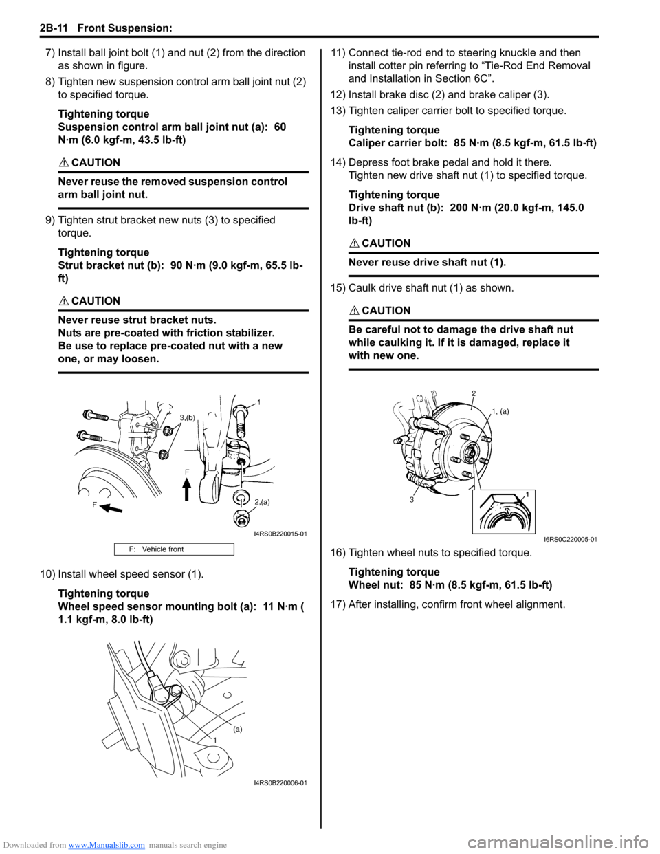
7) Install ball joint bolt (1) and nut (2) from the direction
as shown in figure.
8) Tighten new suspension co ntrol arm ball joint nut (2)
to specified torque.
Tightening torque
Suspension control arm ball joint nut (a): 60
N·m (6.0 kgf-m, 43.5 lb-ft)
CAUTION!
Never reuse the removed suspension control
arm ball joint nut.
9) Tighten strut bracket new nuts (3) to specified torque.
Tightening torque
Strut bracket nut (b): 90 N·m (9.0 kgf-m, 65.5 lb-
ft)
CAUTION!
Never reuse strut bracket nuts.
Nuts are pre-coated with friction stabilizer.
Be use to replace pre-coated nut with a new
one, or may loosen.
10) Install wheel speed sensor (1).
Tightening torque
Wheel speed sensor mounting bolt (a): 11 N·m (
1.1 kgf-m, 8.0 lb-ft) 11) Connect tie-rod end to steering knuckle and then
install cotter pin referrin g to “Tie-Rod End Removal
and Installation in Section 6C”.
12) Install brake disc (2) and brake caliper (3).
13) Tighten caliper carrier bolt to specified torque.
Tightening torque
Caliper carrier bolt: 85 N·m (8.5 kgf-m, 61.5 lb-ft)
14) Depress foot brake pedal and hold it there. Tighten new drive shaft nut (1) to specified torque.
Tightening torque
Drive shaft nut (b): 200 N·m (20.0 kgf-m, 145.0
lb-ft)
CAUTION!
Never reuse drive shaft nut (1).
15) Caulk drive shaft nut (1) as shown.
CAUTION!
Be careful not to damage the drive shaft nut
while caulking it. If it is damaged, replace it
with new one.
16) Tighten wheel nuts to specified torque.
Tightening torque
Wheel nut: 85 N·m (8.5 kgf-m, 61.5 lb-ft)
17) After installing, confirm front wheel alignment.F: Vehicle front
I4RS0B220015-01
1 (a)
I4RS0B220006-01
I6RS0C220005-01
Page 453 of 1496

Downloaded from www.Manualslib.com manuals search engine Front Suspension: 2B-20
Specifications
Tightening Torque SpecificationsS7RS0B2207001
NOTE
The specified tightening torque is also described in the following.
“Front Suspension Construction”
“Front Strut Assembly Components”
“Front Wheel Hub and Steering Knuckle Components”
“Front Suspension Frame, Stabilizer Bar and/or Bushings Components”
Reference:
For the tightening torque of fastener not specified in this section, refer to “Fasteners Information in Section 0A”.
Fastening part
Tightening torque
Note
N ⋅mkgf-mlb-ft
Tie-rod end lock nut 454.5 32.5 �)
Strut bracket nut 909.0 65.5 �) / �)
Brake hose mounting bolt 252.5 18.0 �)
Stabilizer joint nut 505.0 36.5 �) / �)
Strut nut 505.0 36.5 �)
Wheel nut 858.5 61.5 �) / �) / �)
Strut support lower nut 505.0 36.5 �)
Suspension control arm ball joint nut 606.0 43.5 �) / �)
Wheel speed sensor mounting bolt 111.1 8.0 �)
Caliper carrier bolt 858.5 61.5 �)
Drive shaft nut 200 20.0 145.0�)
Suspension control arm front bolt 959.5 68.0 �)
Suspension control arm rear bolt 959.5 68.0 �)
Stabilizer bar mounting bracket bolt 232.3 17.0 �)
Steering gear case mounting No.1 bolt 555.5 40.0 �)
Steering gear case mounting No.2 bolt 555.5 40.0 �)
Front suspension frame mounting bolt 150 15.0 108.5�)
Engine rear mounting bolt 555.5 40.0 �)
Steering shaft joint bolt 252.5 18.5 �)
Wheel bolt 858.5 61.5 �)
Page 462 of 1496
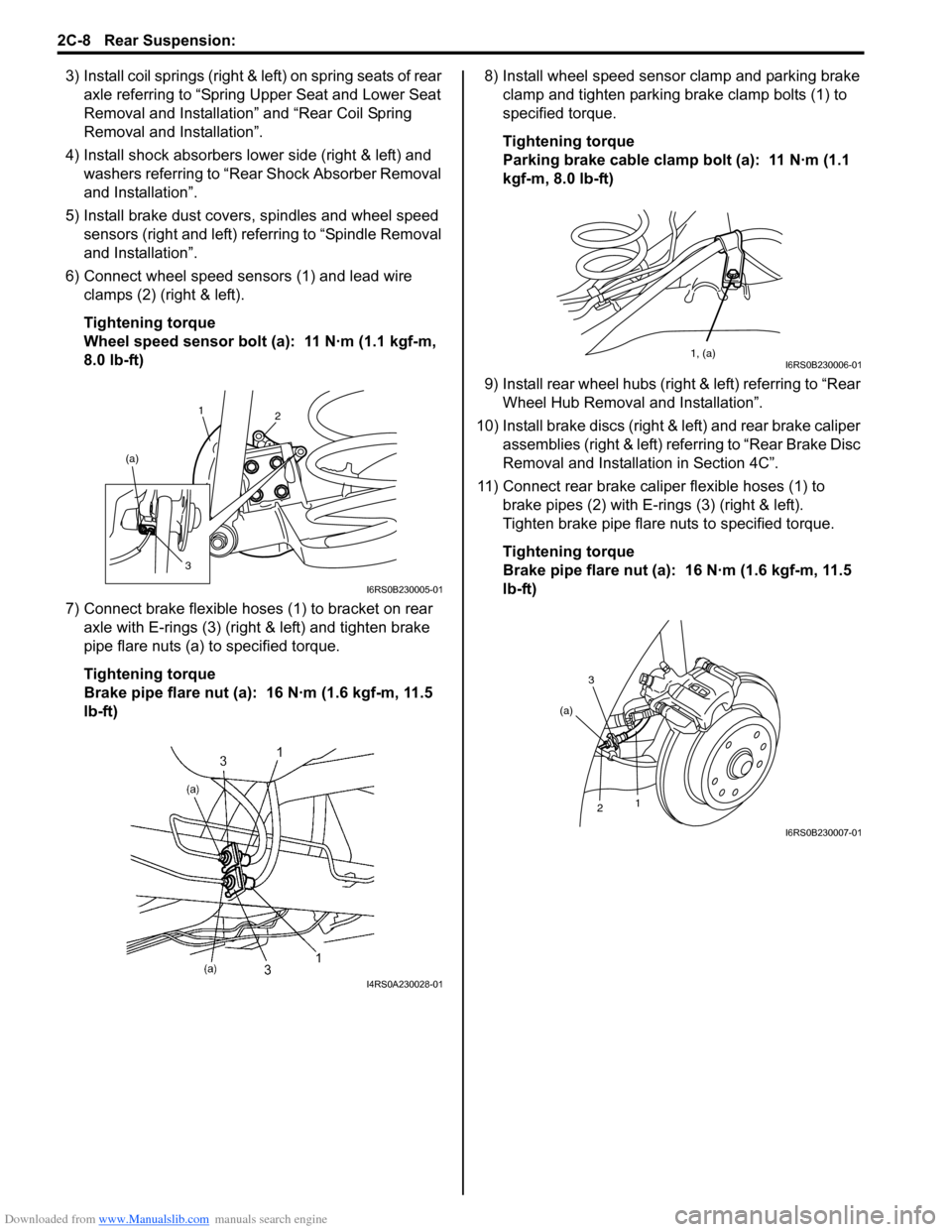
Downloaded from www.Manualslib.com manuals search engine 2C-8 Rear Suspension:
3) Install coil springs (right & left) on spring seats of rear
axle referring to “Spring Upper Seat and Lower Seat
Removal and Installation” and “Rear Coil Spring
Removal and Installation”.
4) Install shock absorbers lower side (right & left) and washers referring to “Rear Shock Absorber Removal
and Installation”.
5) Install brake dust covers, spindles and wheel speed sensors (right and left) referring to “Spindle Removal
and Installation”.
6) Connect wheel speed sensors (1) and lead wire clamps (2) (right & left).
Tightening torque
Wheel speed sensor bolt (a): 11 N·m (1.1 kgf-m,
8.0 lb-ft)
7) Connect brake flexible hoses (1) to bracket on rear axle with E-rings (3) (right & left) and tighten brake
pipe flare nuts (a) to specified torque.
Tightening torque
Brake pipe flare nut (a): 16 N·m (1.6 kgf-m, 11.5
lb-ft) 8) Install wheel speed sensor clamp and parking brake
clamp and tighten parking brake clamp bolts (1) to
specified torque.
Tightening torque
Parking brake cable clamp bolt (a): 11 N·m (1.1
kgf-m, 8.0 lb-ft)
9) Install rear wheel hubs (right & left) referring to “Rear Wheel Hub Removal and Installation”.
10) Install brake discs (right & left) and rear brake caliper assemblies (right & left) referring to “Rear Brake Disc
Removal and Installati on in Section 4C”.
11) Connect rear brake caliper flexible hoses (1) to brake pipes (2) with E-rings (3) (right & left).
Tighten brake pipe flare nuts to specified torque.
Tightening torque
Brake pipe flare nut (a): 16 N·m (1.6 kgf-m, 11.5
lb-ft)
1 2
(a)
3
I6RS0B230005-01
I4RS0A230028-01
1, (a)I6RS0B230006-01
3
2 1
(a)
I6RS0B230007-01
Page 466 of 1496

Downloaded from www.Manualslib.com manuals search engine 2C-12 Rear Suspension:
• Check noise and smooth rotation of wheel by rotating wheel. If it is defect ive, replace bearing.
Spindle Removal and InstallationS7RS0B2306014
Removal
1) Remove rear brake caliper assembly and brake disc. For details, refer to Step 2) to 4) of “Removal” under
“Rear Brake Disc Removal and Installation in
Section 4C”.
2) Remove rear wheel hub. For details, refer to Step 3) to 5) of “Removal” under “Rear Wheel Hub Removal
and Installation”.
3) Disconnect wheel speed sensor (1).
4) Remove brake disc dust cover (2) and spindle (3) from rear axle. Installation
1) Install brake disc dust cover (1), spindle (2) and new spindle bolts (3) and then tighten spindle bolts to
specified torque.
CAUTION!
Never reuse the removed rear spindle bolts.
Bolts are pre-coated wi th friction stabilizer.
Be sure to replace pre-coated bolt with a new
one, or bolt may loosen.
Tightening torque
Rear spindle bolt (a): 88 N·m (8.8 kgf-m, 64.0 lb-
ft)
2) Connect wheel speed sensor (4) and tighten wheel speed sensor bolt to specified torque.
Tightening torque
Wheel speed sensor bolt (b): 11 N·m (1.1 kgf-m,
8.0 lb-ft)
3) Install rear wheel hub re ferring to “Rear Wheel Hub
Removal and Installation”.
4) Install brake disc and rear brake caliper assembly referring to “Rear Brake Disc Removal and
Installation in Section 4C”.
5) Install wheel and tighten wheel nuts to specified torque.
Tightening torque
Wheel nut: 85 N·m (8.5 kgf-m, 61.5 lb-ft)
6) Adjust parking brake cable. For adjustment, see “Parking Brake Inspection and Adjustment in Section
4D”.
7) Perform brake test (foot brake and parking brake).
8) Check each installed part for fluid leakage.
I3RM0A230050-01
2
1 3
I6RS0B230015-01
1
(b)
4
2
3, (a)
I6RS0B230016-01