2006 SUZUKI SWIFT crank case pulley
[x] Cancel search: crank case pulleyPage 53 of 1496

Downloaded from www.Manualslib.com manuals search engine Engine General Information and Diagnosis: 1A-3
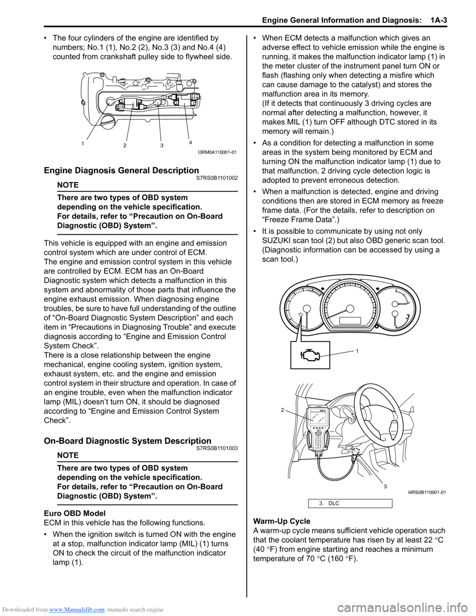
• The four cylinders of the engine are identified by numbers; No.1 (1), No.2 (2 ), No.3 (3) and No.4 (4)
counted from crankshaft pulley side to flywheel side.
Engine Diagnosis General DescriptionS7RS0B1101002
NOTE
There are two types of OBD system
depending on the vehicle specification.
For details, refer to “Precaution on On-Board
Diagnostic (OBD) System”.
This vehicle is equipped with an engine and emission
control system which are under control of ECM.
The engine and emission control system in this vehicle
are controlled by ECM. ECM has an On-Board
Diagnostic system which detects a malfunction in this
system and abnormality of those parts that influence the
engine exhaust emission. When diagnosing engine
troubles, be sure to have full understanding of the outline
of “On-Board Diagnostic System Description” and each
item in “Precautions in Diagnosing Trouble” and execute
diagnosis according to “Engine and Emission Control
System Check”.
There is a close relationship between the engine
mechanical, engine cooling system, ignition system,
exhaust system, etc. and the engine and emission
control system in their structure and operation. In case of
an engine trouble, even when the malfunction indicator
lamp (MIL) doesn’t turn ON, it should be diagnosed
according to “Engine and Emission Control System
Check”.
On-Board Diagnostic System DescriptionS7RS0B1101003
NOTE
There are two types of OBD system
depending on the vehicle specification.
For details, refer to “Precaution on On-Board
Diagnostic (OBD) System”.
Euro OBD Model
ECM in this vehicle has the following functions.
• When the ignition switch is turned ON with the engine at a stop, malfunction indicator lamp (MIL) (1) turns
ON to check the circuit of the malfunction indicator
lamp (1). • When ECM detects a malfunction which gives an
adverse effect to vehicle emission while the engine is
running, it makes the malfunction indicator lamp (1) in
the meter cluster of the inst rument panel turn ON or
flash (flashing only when detecting a misfire which
can cause damage to the catalyst) and stores the
malfunction area in its memory.
(If it detects that contin uously 3 driving cycles are
normal after detecting a malfunction, however, it
makes MIL (1) turn OFF although DTC stored in its
memory will remain.)
• As a condition for detecting a malfunction in some areas in the system being monitored by ECM and
turning ON the malfunction indicator lamp (1) due to
that malfunction, 2 driving cycle detection logic is
adopted to prevent erroneous detection.
• When a malfunction is detected, engine and driving conditions then are stored in ECM memory as freeze
frame data. (For the details, refer to description on
“Freeze Frame Data”.)
• It is possible to communicate by using not only SUZUKI scan tool (2) but also OBD generic scan tool.
(Diagnostic information can be accessed by using a
scan tool.)
Warm-Up Cycle
A warm-up cycle means sufficie nt vehicle operation such
that the coolant temperature has risen by at least 22 °C
(40 °F) from engine starting and reaches a minimum
temperature of 70 °C (160 ° F).
1
23 4
I3RM0A110001-01
3. DLC
2
3
1
I4RS0B110001-01
Page 291 of 1496

Downloaded from www.Manualslib.com manuals search engine Engine Mechanical: 1D-6
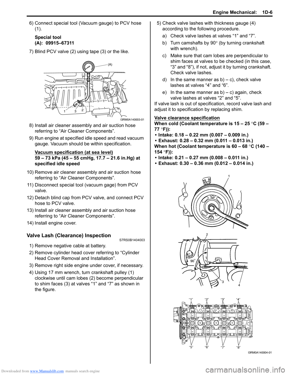
6) Connect special tool (Vacuum gauge) to PCV hose (1).
Special tool
(A): 09915–67311
7) Blind PCV valve (2) using tape (3) or the like.
8) Install air cleaner assembly and air suction hose referring to “Air Cleaner Components”.
9) Run engine at specified idle speed and read vacuum gauge. Vacuum should be within specification.
Vacuum specification (at sea level)
59 – 73 kPa (45 – 55 cmHg, 17.7 – 21.6 in.Hg) at
specified idle speed
10) Remove air cleaner assembly and air suction hose referring to “Air Cleaner Components”.
11) Disconnect special tool (vacuum gage) from PCV valve.
12) Detach blind cap from PCV valve, and connect PCV hose to PCV valve.
13) Install air cleaner assembly and air suction hose referring to “Air Cleaner Components”.
14) Install engine cover.
Valve Lash (Clearance) InspectionS7RS0B1404003
1) Remove negative cable at battery.
2) Remove cylinder head cover referring to “Cylinder Head Cover Removal and Installation”.
3) Remove right side engine under cover, if necessary.
4) Using 17 mm wrench, turn crankshaft pulley (1) clockwise until cam lobes (2) become perpendicular
to shim faces (3) at valves “1” and “7” as shown in
the figure. 5) Check valve lashes with thickness gauge (4)
according to the following procedure.
a) Check valve lashes at valves “1” and “7”.
b) Turn camshafts by 90 ° (by turning crankshaft
with wrench).
c) Make sure that cam lobes are perpendicular to shim faces at valves to be checked (in this case,
“3” and “8”), if not, adjust it by turning crankshaft.
Check valve lashes.
d) In the same manner as b) – c), check valve
lashes at valves “4” and “6”.
e) In the same manner as b) – c) again, check valve lashes at valves “2” and “5”.
If valve lash is out of specification, record valve lash and
adjust it to specification by replacing shim.
Valve clearance specification
When cold (Coolant te mperature is 15 – 25 °C (59 –
77 °F)):
• Intake: 0.18 – 0.22 mm (0.007 – 0.009 in.)
• Exhaust: 0.28 – 0.32 mm (0.011 – 0.013 in.)
When hot (Coolant temperature is 60 – 68 °C (140 –
154 °F)):
• Intake: 0.21 – 0.27 mm (0.008 – 0.011 in.)
• Exhaust: 0.30 – 0.36 mm (0.012 – 0.014 in.)
(A)
13 2
I3RM0A140003-01
I3RM0A140004-01
Page 414 of 1496

Downloaded from www.Manualslib.com manuals search engine 1J-4 Charging System:
Diagnostic Information and Procedures
Battery InspectionS7RS0B1A04001
Common Causes of Failure
A battery is not designed to last indefinitely; however, with proper care, it will provide many years of service. If the
battery performs satisfactorily during te st but fails to operate properly for no apparent reason, the following are some
factors that may point to the cause of trouble:
• Accessories left on overnight or for an extended period without the generator operating.
• Slow average driving speeds for short periods.
• Electrical load exceeding generator output partic ularly with addition of aftermarket equipment.
• Defects in charging system such as high resistance, s lipping drive belt, loose generator output terminal, faulty
generator or voltage regulator, Refer to “Generator Symptom Diagnosis”.
• Battery abuse, including failure to keep battery cable terminals clean and tight or loose battery hold down.
• Mechanical problems in electrical sys tem such as shorted or pinched wires.
Visual Inspection
Check for obvious damage, such as cracked or broken case or cover, that could permit loss of electrolyte. If obvious
damage is noted, replace battery. Determine cause of damage and correct as needed.
Generator Symptom DiagnosisS7RS0B1A04002
CAUTION!
• Do not mistake polarities of “IG” terminal and “L” terminal.
• Do not create short circuit between “IG” and “L” terminals. Always connect these terminals through a lamp.
• Do not connect any load between “L” and “E” terminals.
• When connecting charger or booster battery to vehicle battery, refer to “Jump Starting in Case of Emergency”.
Trouble in charging system will show up as one or more of the following conditions:
1) Faulty indicator lamp operation.
2) An undercharged battery as evidenced by slow cranking or indicator dark.
3) An overcharged battery as evidenced by ex cessive spewing of electrolyte from vents.
Condition Possible cause Correction / Reference Item
Noisy generator Loose drive belt Adjust or replace drive belt.
Loose drive belt pulley Tighten by specified torque.
Loose mounting bolts Tighten by specified torque.
Worn or dirty bearings Replace.
Defective diode or stator Replace.
Charge light does not
light with ignition ON and
engine off Fuse blown
Replace fuse and check for shorted circuit.
Indicator lamp (LED) faulty Replace combination meter.
Wiring connection loose Tighten loose connection.
IC regulator or field coil faulty Replace.
Poor contact between brush and slip
ring Repair or replace.
Charge light does not go
out with engine running
(battery requires frequent
recharging) Drive belt loose or worn
Adjust or replace drive belt.
IC regulator or generator faulty Replace.
Wiring faulty Repair wiring.