2006 SUZUKI SWIFT Push nut
[x] Cancel search: Push nutPage 440 of 1496
Downloaded from www.Manualslib.com manuals search engine 2B-7 Front Suspension:
3) Install bump stopper onto strut rod. For installing
direction, refer to the figure in “Front Suspension
Construction”.
4) Pull strut rod as far up as possible and use care not to allow it to re tract into strut.
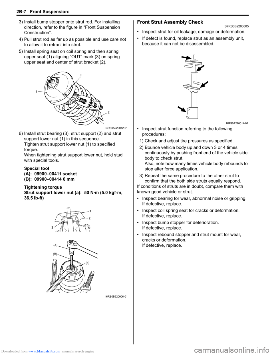
5) Install spring seat on coil spring and then spring upper seat (1) aligning “OUT” mark (3) on spring
upper seat and center of strut bracket (2).
6) Install strut bearing (3), strut support (2) and strut
support lower nut (1) in this sequence.
Tighten strut support lower nut (1) to specified
torque.
When tightening strut support lower nut, hold stud
with special tools.
Special tool
(A): 09900–00411 socket
(B): 09900–00414 6 mm
Tightening torque
Strut support lower nut (a): 50 N·m (5.0 kgf-m,
36.5 lb-ft)Front Strut Assembly CheckS7RS0B2206005
• Inspect strut for oil leakage, damage or deformation.
• If defect is found, replace strut as an assembly unit, because it can not be disassembled.
• Inspect strut function re ferring to the following
procedures:
1) Check and adjust tire pressures as specified.
2) Bounce vehicle body up and down 3 or 4 times continuously by pushing front end of the vehicle side
body to check strut.
Also, note how many times vehicle body rebounds to
stop after force application.
3) Repeat the same procedure to the other strut to confirm that the both side struts equally respond.
If conditions of struts are in doubt, compare them with
known-good vehicle or strut.
• Inspect bearing for wear, abnormal noise or gripping. If defective, replace.
• Inspect coil spring seat for cracks or deformation.
If defective, replace.
• Inspect bump stopper for deterioration. If defective, replace.
• Inspect rebound stopper and strut mount for wear, cracks or deformation.
If defective, replace.
I4RS0A220012-01
I6RS0B220006-01
I4RS0A220014-01
Page 446 of 1496
Downloaded from www.Manualslib.com manuals search engine 2B-13 Front Suspension:
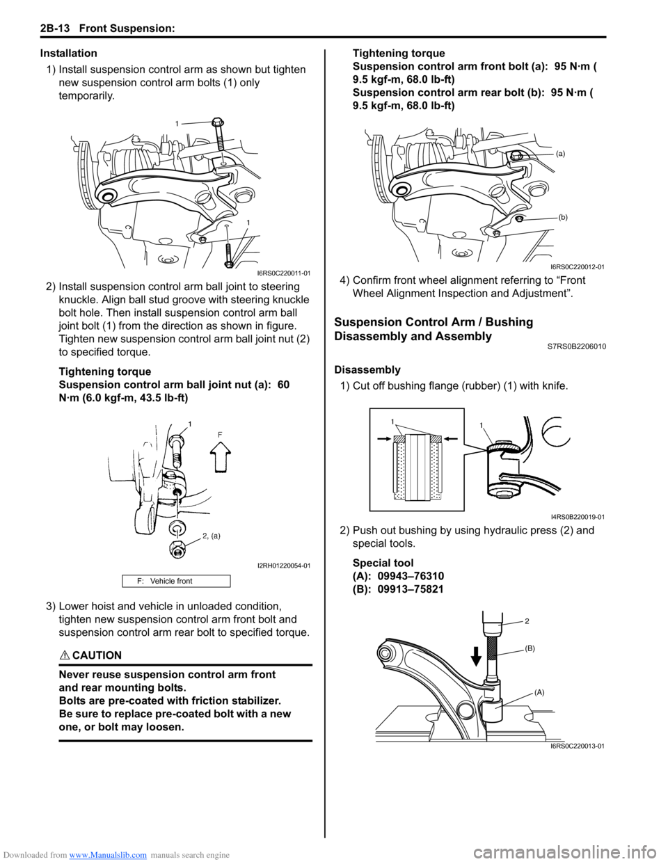
Installation1) Install suspension control arm as shown but tighten new suspension contro l arm bolts (1) only
temporarily.
2) Install suspensi on control arm ball joint to steering
knuckle. Align ball stud gr oove with steering knuckle
bolt hole. Then install su spension control arm ball
joint bolt (1) from the direction as shown in figure.
Tighten new suspension cont rol arm ball joint nut (2)
to specified torque.
Tightening torque
Suspension control arm ball joint nut (a): 60
N·m (6.0 kgf-m, 43.5 lb-ft)
3) Lower hoist and vehicle in unloaded condition, tighten new suspension control arm front bolt and
suspension control arm rear bolt to specified torque.
CAUTION!
Never reuse suspension control arm front
and rear mounting bolts.
Bolts are pre-coated with friction stabilizer.
Be sure to replace pre-coated bolt with a new
one, or bolt may loosen.
Tightening torque
Suspension control arm front bolt (a): 95 N·m (
9.5 kgf-m, 68.0 lb-ft)
Suspension control arm re ar bolt (b): 95 N·m (
9.5 kgf-m, 68.0 lb-ft)
4) Confirm front wheel alignment referring to “Front Wheel Alignment Inspection and Adjustment”.
Suspension Control Arm / Bushing
Disassembly and Assembly
S7RS0B2206010
Disassembly
1) Cut off bushing flange (rubber) (1) with knife.
2) Push out bushing by using hydraulic press (2) and special tools.
Special tool
(A): 09943–76310
(B): 09913–75821
F: Vehicle front
1
1
I6RS0C220011-01
I2RH01220054-01
(a)(b)
I6RS0C220012-01
I4RS0B220019-01
2
(A)
(B)
I6RS0C220013-01
Page 513 of 1496
Downloaded from www.Manualslib.com manuals search engine Brake Control System and Diagnosis: 4A-15
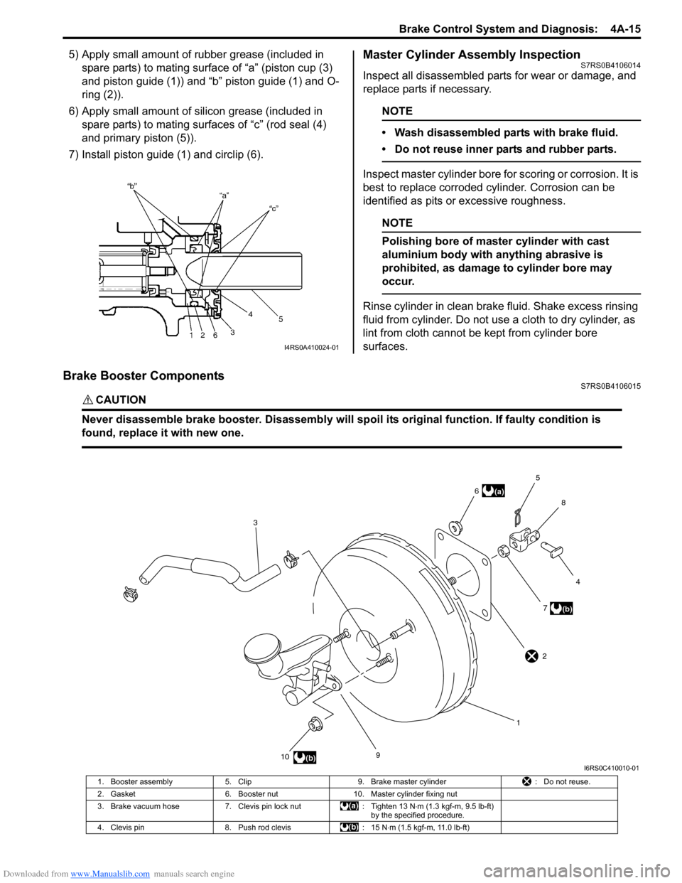
5) Apply small amount of rubber grease (included in spare parts) to mating surface of “a” (piston cup (3)
and piston guide (1)) and “b” piston guide (1) and O-
ring (2)).
6) Apply small amount of s ilicon grease (included in
spare parts) to mating surfaces of “c” (rod seal (4)
and primary piston (5)).
7) Install piston guide (1) and circlip (6).Master Cylinder Assembly InspectionS7RS0B4106014
Inspect all disassembled parts for wear or damage, and
replace parts if necessary.
NOTE
• Wash disassembled parts with brake fluid.
• Do not reuse inner parts and rubber parts.
Inspect master cylinder bore for scoring or corrosion. It is
best to replace corroded cylinder. Corrosion can be
identified as pits or excessive roughness.
NOTE
Polishing bore of master cylinder with cast
aluminium body with anything abrasive is
prohibited, as damage to cylinder bore may
occur.
Rinse cylinder in clean brake fluid. Shake excess rinsing
fluid from cylinder. Do not use a cloth to dry cylinder, as
lint from cloth cannot be kept from cylinder bore
surfaces.
Brake Booster ComponentsS7RS0B4106015
CAUTION!
Never disassemble brake booster. Disassembly will spoi l its original function. If faulty condition is
found, replace it with new one.
I4RS0A410024-01
9
10 17
4
8
5
6
3
(b)
(a)
(b)
2
I6RS0C410010-01
1. Booster assembly 5. Clip 9. Brake master cylinder : Do not reuse.
2. Gasket 6. Booster nut 10. Master cylinder fixing nut
3. Brake vacuum hose 7. Clevis pin lock nut : Tighten 13 N⋅m (1.3 kgf-m, 9.5 lb-ft)
by the specified procedure.
4. Clevis pin 8. Push rod clevis : 15 N⋅m (1.5 kgf-m, 11.0 lb-ft)
Page 515 of 1496
Downloaded from www.Manualslib.com manuals search engine Brake Control System and Diagnosis: 4A-17
2) Hold brake pedal depressed for 30 seconds. If pedal height does not change, condition is good. But it isn’t
if pedal rises.
Brake Booster Removal and InstallationS7RS0B4106017
Removal
1) Recover refrigerant from A/C system by using recovery and recycling equipment referring to
“Operation Procedure for Refrigerant Charge in
Section 7B” or “Operation Procedure for Refrigerant
Charge in Section 7B”.
2) Remove master cylinder assembly from booster referring to “Master Cylin der Assembly Removal and
Installation”.
3) Remove cowl top cover and cowl top panel referring to “Cowl Top Components in Section 9K”.
4) Remove suction hose referring to “Major Components of A/C System in Section 7B” or “Major
Components of A/C System in Section 7B”.
5) Disconnect vacuum hose from booster referring to “Brake Booster Components”.
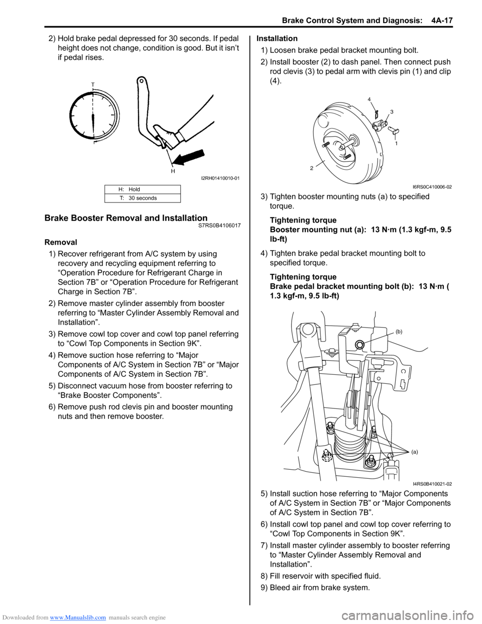
6) Remove push rod clevis pin and booster mounting nuts and then remove booster. Installation
1) Loosen brake pedal bracket mounting bolt.
2) Install booster (2) to dash panel. Then connect push rod clevis (3) to pedal arm with clevis pin (1) and clip
(4).
3) Tighten booster mounting nuts (a) to specified torque.
Tightening torque
Booster mounting nut (a): 13 N·m (1.3 kgf-m, 9.5
lb-ft)
4) Tighten brake pedal bracket mounting bolt to specified torque.
Tightening torque
Brake pedal bracket mounting bolt (b): 13 N·m (
1.3 kgf-m, 9.5 lb-ft)
5) Install suction hose referring to “Major Components of A/C System in Section 7B” or “Major Components
of A/C System in Section 7B”.
6) Install cowl top panel and cowl top cover referring to
“Cowl Top Components in Section 9K”.
7) Install master cylinder assembly to booster referring to “Master Cylinder Assembly Removal and
Installation”.
8) Fill reservoir with specified fluid.
9) Bleed air from brake system.
H: Hold
T: 30 seconds
I2RH01410010-01
1
2 4
3
I6RS0C410006-02
(b)
(a)
I4RS0B410021-02
Page 516 of 1496
Downloaded from www.Manualslib.com manuals search engine 4A-18 Brake Control System and Diagnosis:
10) Check pedal height and play referring to “Brake Pedal Free Height Inspection” and “Brake Pedal
Play Inspection”.
11) Check each installed part for fluid leakage and perform brake test.
12) Evacuate and charge refrigerant by referring to “Evacuating of A/C Syst em” and “Procedure of
Charging” under “Operation Procedure for
Refrigerant Charge in Section 7B” or “Operation
Procedure for Refrigerant Charge in Section 7B”.
Brake Booster Inspection and AdjustmentS7RS0B4106018
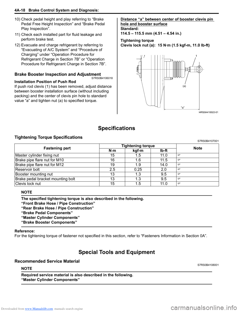
Installation Position of Push Rod
If push rod clevis (1) has b een removed, adjust distance
between booster installation surface (without including
packing) and the center of clevis pin hole to standard
value “a” and tighten nut (a) to specified torque. Distance “a” between center of booster clevis pin
hole and booster surface
Standard:
114.5 – 115.5 mm (4.51 – 4.54 in.)
Tightening torque
Clevis lock nut (a): 15 N·m (1.5 kgf-m, 11.0 lb-ft)
Specifications
Tightening Torque SpecificationsS7RS0B4107001
NOTE
The specified tightening torque is also described in the following.
“Front Brake Hose / Pipe Construction”
“Rear Brake Hose / Pipe Construction”
“Brake Pedal Components”
“Master Cylinder Components”
“Brake Booster Components”
Reference:
For the tightening torque of fastener not specified in this
section, refer to “Fasteners Information in Section 0A”.
Special Tools and Equipment
Recommended Service MaterialS7RS0B4108001
NOTE
Required service material is also described in the following.
“Master Cylinder Components”
I4RS0A410022-01
Fastening part Tightening torque
Note
N ⋅mkgf-mlb-ft
Master cylinder fixing nut 15 1.5 11.0 �)
Brake pipe flare nut for M10 16 1.6 11.5 �)
Brake pipe flare nut for M12 19 1.9 14.0 �)
Reservoir bolt 2.5 0.25 2.0 �)
Booster mounting nut 13 1.3 9.5 �)
Brake pedal bracket mounting bolt 13 1.3 9.5 �)
Clevis lock nut 15 1.5 11.0 �)
Page 532 of 1496

Downloaded from www.Manualslib.com manuals search engine 4C-8 Rear Brakes:
Rear Disc Brake Caliper InspectionS7RS0B4306006
Pin Boot and Cylinder Boot
Check boots (1) for breakage, crack and damage.
If defective, replace.
Disc Brake Piston
Check all around piston for rust, corrosion and any other
damage.
If it is found faulty, replace.
Caliper
Push in adjusting bolt (1) by hand and move lever to
check that adjusting bolt (1) moves smoothly in the
arrow direction.
Also, check adjusting bolt (1) for any damage. If it is
found faulty, replace.
Slide Pin
Check guide pin for smooth movement.
If it is found faulty, correct or replace.
Apply rubber grease to guide pin outer surface. Rubber
grease should be the one whose viscosity is less
affected by such low temperature as –40 °C (–40 ° F).
Rear Flexible Hose Removal and InstallationS7RS0B4306007
Removal
1) Hoist vehicle and remove tire and wheel.
2) Remove caliper (4) assembly referring to “Rear Disc Brake Caliper Disassembly and Assembly”.
3) Loosen brake pipe flare nut (1) using by flare nut wrench.
4) Remove clip (2).
5) Remove brake flexible hose (3) from brake pipe.
Installation
Install reverse order of removal nothing the following.
• Tighten brake pipe flare nut to specified torque.
Tightening torque
Brake pipe flare nut (a): 16 N·m (1.6 kgf-m, 12.0 lb-ft)
1 1
1
I6RS0B431019-01
I6RS0B431020-01
1
I6RS0B431021-01
1
2
3
4
I6RS0C430013-01
Page 820 of 1496
Downloaded from www.Manualslib.com manuals search engine 5B-6 Manual Transmission/Transaxle:
Gear Shift Control Lever and Cable Removal
and Installation
S7RS0B5206004
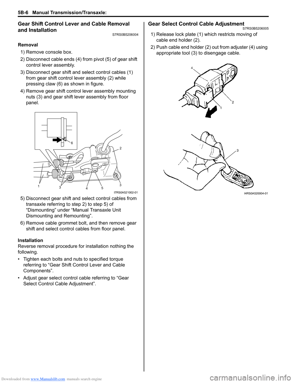
Removal1) Remove console box.
2) Disconnect cable ends (4) from pivot (5) of gear shift control lever assembly.
3) Disconnect gear shift and select control cables (1) from gear shift control lever assembly (2) while
pressing claw (6) as shown in figure.
4) Remove gear shift control lever assembly mounting nuts (3) and gear shift lever assembly from floor
panel.
5) Disconnect gear shift and select control cables from transaxle referring to step 2) to step 5) of
“Dismounting” under “Manual Transaxle Unit
Dismounting and Remounting”.
6) Remove cable grommet bolt, and then remove gear shift and select control cables from floor panel.
Installation
Reverse removal procedure for installation nothing the
following.
• Tighten each bolts and nuts to specified torque referring to “Gear Shift Control Lever and Cable
Components”.
• Adjust gear select control cable referring to “Gear Select Control Cable Adjustment”.
Gear Select Control Cable AdjustmentS7RS0B5206005
1) Release lock plate (1) which restricts moving of cable end holder (2).
2) Push cable end holder (2) out from adjuster (4) using appropriate tool (3) to disengage cable.
35
4
2
31
6
I7RS0A521002-01I4RS0A520004-01
Page 854 of 1496

Downloaded from www.Manualslib.com manuals search engine 5C-2 Clutch:
Diagnostic Information and Procedures
Clutch System Symptom DiagnosisS7RS0B5304001
Repair Instructions
Clutch Pedal InspectionS7RS0B5306001
Cylinder Push Rod Play “A”1) Press clutch pedal (1) gradually with finger, stop when slight increase of resistance is felt and
measure how much pedal has moved (push rod
play) as represented by “A” as shown.
Push rod play
“A”: Max. 3 mm (0.12 in.)
2) If “A” is not within specification, replace master cylinder (3) or pedal arm (2). Clutch Pedal Free Travel “B”
1) Depress clutch pedal (1), stop the moment clutch resistance is felt, and measure how much pedal has
moved (clutch pedal free travel) as represented by
“B” in figure.
Clutch pedal free travel
“B”
: 2 – 8 mm (0.08 – 0.31 in.)
2) If “B” is not within specification, check pedal arm (2) and master cylinder (3) and replace defective part.
Condition Possible cause Correction / Reference Item
Slipping Improper clutch pedal free travel Replace master cylinder or clutch pedal arm.
Worn or oily clutch disc facing Replace disc.
Warped disc, pressure plate or flywheel
surface Replace disc, clutch cover or flywheel.
Weakened diaphragm spring Replace clutch cover.
Master cylinder piston or seal cup not
returning Replace master cylinder.
Dragging clutch Improper clutch pedal free travel Replace master cylinder or clutch pedal arm.
Weakened diaphragm spring, or worn
spring tip Replace clutch cover.
Rusted input shaft splines Lubricate.
Damaged or worn splines of transaxle
input shaft Replace input shaft.
Excessively wobbly clutch disc Replace disc.
Clutch facings broken or dirty with oil Replace disc.
Fluid leakage Repair or replace.
Clutch vibration Glazed (glass-like) clutch facings Repair or replace disc.
Clutch facings dirty with oil Replace disc.
Release bearing slides unsmoothly on
input shaft bearing retainer Lubricate or replace input shaft bearing
retainer.
Wobbly clutch disc, or poor facing
contact Replace disc.
Weakened torsion springs in clutch disc Replace disc.
Clutch disc rivets loose Replace disc.
Distorted pressure plate or flywheel
surface Replace clutch cover or flywheel.
Weakened engine mounting Replace engine mounting.
Loosened engine mounting bolt or nut Retighten engine mounting bolt or nut.
Noisy clutch Worn or broken release bearing Replace release bearing.
Input shaft front bearing worn down Replace input shaft bearing.
Excessive rattle of clutch disc hub Replace disc.
Cracked clutch disc Replace disc.
Pressure plate and diaphragm spring
rattling Replace clutch cover.
Grabbing clutch Clutch disc facings soaked with oil Replace disc.
Clutch disc facings excessively worn Replace disc.
Rivet heads showing out of facing Replace disc.
Weakened torsion springs Replace disc.