2006 SUZUKI SWIFT inlet manifold
[x] Cancel search: inlet manifoldPage 302 of 1496

Downloaded from www.Manualslib.com manuals search engine 1D-17 Engine Mechanical:
Engine Assembly Removal and InstallationS7RS0B1406011
NOTE
After replacing electric throttle body
assembly, perform calibration of throttle
valve referring to “Electric Throttle Body
System Calibration in Section 1C”.
Removal1) Relieve fuel pressure according to “Fuel Pressure Relief Procedure in Section 1G”.
2) Disconnect negative and pos itive cable at battery.
3) Remove battery and tray.
4) Remove engine hood after disconnecting windshield washer hose.
5) Remove right and left side engine under covers.
6) Remove A/C compressor belt by referring to “Compressor Drive Belt Remo val and Installation in
Section 7B” or “Compressor Drive Belt Removal and
Installation in Section 7B”.
7) Drain engine oil, transaxle oil and coolant.
8) Remove cowl top plate referring to “Cowl Top Components in Section 9K”.
9) Remove air cleaner assembly referring to “Air Cleaner Components”.
10) With hose connected, detach A/C compressor from its bracket (A/C model) referring to “Compressor
Assembly Removal and Installation in Section 7B” or
“Compressor Assembly Removal and Installation in
Section 7B”.
CAUTION!
Suspend removed A/C compressor at a place
where no damage will be caused during
removal and installation of engine assembly.
11) Remove intake manifold rear stiffener (1) from intake manifold and cylinder block. 12) Disconnect the following electric wires:
• MAP sensor (1)
• ECT sensor (2)
•EGR valve (3)
• CMP sensor (4)
• Electric throttle body assembly (5)
• Ignition coil assembly (6)
• Injectors (7)
• Heated oxygen sensor No. 2 (8) and No. 1 (9)
• Oil control valve (10)
• Engine oil pressure switch (11)
• CKP sensor (12)
• Knock sensor (13)
• Back up light switch (14)
• Generator (15)
• Starting motor (16)
• Ground terminal (17) from intake manifold
• Battery ground terminal (18) from exhaust manifold
• Battery ground cable (19) from transaxle
• Magnet clutch switch of A/C compressor (A/C model)
• Each wire harness clamps
• Output shaft speed sensor (VSS) (34) (A/T model)
• Solenoid valve (33) (A/T model)
• Transmission range sensor (32) (A/T model)
• Input shaft speed sensor (31) (A/T model)
13) Remove fuse box from its bracket.
14) Disconnect the following cables: • Gear select control cable (23) (M/T model)
• Gear shift control cable (24) (M/T model)
• A/T select cable (A/T model)
15) Disconnect the following hoses: • Brake booster hose (26) from intake manifold
• Radiator inlet and outlet hoses (20) from each pipe
• Heater inlet and outlet hoses (21) from each pipe
• Fuel feed hoses (22) from fuel feed pipe
• EVAP canister purge valve hose (30) from purge pipe
• A/T fluid cooler hoses (A/T model)
16) With hose connected, detach clutch operating cylinder (25). (M/T model)
CAUTION!
Suspend removed clutch operating cylinder
at a place where no damage will be caused
during removal and installation of engine
assembly.
1
I6RS0B141014-01
Page 356 of 1496

Downloaded from www.Manualslib.com manuals search engine 1E-4 Engine Lubrication System:
Heat Exchanger On-Vehicle InspectionS7RS0B1506002
• Check heat exchanger for deformation wear or damage.
• Check heat exchanger for coolant leakage and oil leakage.
If any malcondition is found, replace O-ring, stand bolt
gasket and/or heat exchanger.
Heat Exchanger Removal and InstallationS7RS0B1506003
Removal
1) Drain engine oil by removing drain plug.
2) Drain coolant referring to “Cooling System Draining in Section 1F”.
3) Remove exhaust manifold referring to “Exhaust Manifold Removal and Inst allation in Section 1K”.
4) Remove heat exchanger inlet No. 1 hose and outlet No. 1 hose.
5) Remove heat exchanger, O-ring and gasket by removing heat exchanger stand bolt. Installation
Reverse removal procedure for installation noting the
followings.
• Use new stand bolt gasket.
• Apply engine oil to new O-ring and install it to heat
exchanger.
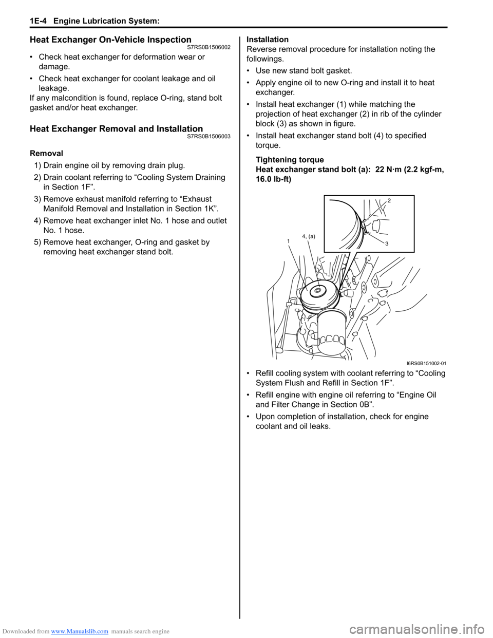
• Install heat exchanger (1) while matching the projection of heat exchanger (2) in rib of the cylinder
block (3) as shown in figure.
• Install heat exchanger stand bolt (4) to specified torque.
Tightening torque
Heat exchanger stand bolt (a): 22 N·m (2.2 kgf-m,
16.0 lb-ft)
• Refill cooling system with co olant referring to “Cooling
System Flush and Refill in Section 1F”.
• Refill engine with engine oil referring to “Engine Oil and Filter Change in Section 0B”.
• Upon completion of installation, check for engine coolant and oil leaks.
2
3
4, (a)
1
I6RS0B151002-01
Page 371 of 1496

Downloaded from www.Manualslib.com manuals search engine Engine Cooling System: 1F-8
Thermostat Removal and InstallationS7RS0B1606007
Removal1) Drain coolant referring to “Cooling System Draining”.
2) Remove intake manifold referring to “Intake Manifold Removal and Installa tion in Section 1D”.
3) Remove generator referring to “Generator Dismounting and Remounting in Section 1J”.
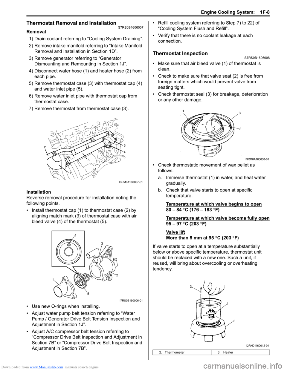
4) Disconnect water hose (1) and heater hose (2) from each pipe.
5) Remove thermostat case (3) with thermostat cap (4)
and water inlet pipe (5).
6) Remove water inlet pipe with thermostat cap from thermostat case.
7) Remove thermostat from thermostat case (3).
Installation
Reverse removal procedure for installation noting the
following points.
• Install thermostat cap (1) to thermostat case (2) by aligning match mark (3) of thermostat case with air
bleed valve (4) of the thermostat (5).
• Use new O-rings when installing.
• Adjust water pump belt tension referring to “Water Pump / Generator Drive Belt Tension Inspection and
Adjustment in Section 1J”.
• Adjust A/C compressor belt tension referring to “Compressor Drive Belt Inspection and Adjustment in
Section 7B” or “Compressor Drive Belt Inspection and
Adjustment in Section 7B”. • Refill cooling system referrin
g to Step 7) to 22) of
“Cooling System Flush and Refill”.
• Verify that there is no coolant leakage at each connection.
Thermostat InspectionS7RS0B1606008
• Make sure that air bleed valve (1) of thermostat is clean.
• Check to make sure that va lve seat (2) is free from
foreign matters which would prevent valve from
seating tight.
• Check thermostat seal (3) for breakage, deterioration or any other damage.
• Check thermostatic movement of wax pellet as follows:
a. Immerse thermostat (1) in water, and heat water gradually.
b. Check that valve starts to open at specific temperature.
Temperature at which valve begins to open
80 – 84 °C (176 – 183 °F)
Temperature at which valve become fully open
95 – 97 °C (203 °F)
Va l v e l i ft
More than 8 mm at 95 °C (203 ° F)
If valve starts to open at a temperature substantially
below or above specific temperature, thermostat unit
should be replaced with a new one. Such a unit, if
reused, will bring about ov ercooling or overheating
tendency.
I3RM0A160007-01
4
5 3
1 2
I7RS0B160006-01
2. Thermometer
3. Heater
I3RM0A160008-01
I2RH01160012-01
Page 958 of 1496

Downloaded from www.Manualslib.com manuals search engine 7B-10 Air Conditioning System: Manual Type
Abnormal Noise from Tension Pulley
Abnormal Noise from A/C Evaporator
Abnormal Noise from Blower Motor
A/C System Performance InspectionS7RS0B7214003
1) Confirm that vehicle and environmental conditions are as follows.
• Vehicle is put indoors.
• Ambient temperature is within 25 – 35 °C (77 – 95
° F).
• Relative humidity is within 30 – 70%.
• There is no wind indoors.
• HVAC unit is normal.
• Blower motor is normal.
• There is no air leakage from air ducts.
• Condenser fins are clean.
• Air filter in HVAC unit is not clogged with dirt and
dust.
• Battery voltage is about 12 V.
• Radiator cooling fan operates normally.
2) Make sure that high pressure valve (1) and low pressure valve (2) of manifold gauge are firmly
closed.
3) Connect high pressure charging hose (3) to high pressure service valve (5) on vehicle and low
pressure charging hose (4) to low pressure service
valve (6).
4) Bleed the air in charging hoses (3) and (4) by loosening their nuts respectively utilizing the
refrigerant pressure. When a hissing sound is heard,
immediately tighten nut.
CAUTION!
Do not connect high and low pressure
charging hoses in reverse.
Condition Possible cause Correction / Reference Item
Clattering noise is heard
from pulley Worn or damaged bearing
Replace tension pulley.
Pulley cranks upon
contact Cracked or loose bracket
Replace or retighten bracket.
ConditionPossible cause Correction / Reference Item
Whistling sound is heard
from A/C evaporator Depending on the combination of the
interior / exterior temperatures, engine
rpm and refrigerant pressure, the
refrigerant flowing out of the expansion
valve may, under certain conditions,
make a whistling sound At times, slightly decrea
sing refrigerant volume
may stop this noise.
Inspect expansion valve and replace if faulty.
Condition Possible cause Correction / Reference Item
Blower motor emits a
chirping sound in
proportion to its speed of
rotation Worn or damaged motor brushes or
commutator
Replace blower motor.
Fluttering noise or large
droning noise is heard
from blower motor Leaves or other debris introduced from
fresh air inlet to blower motor
Remove debris and make sure that the screen
at fresh air inlet is intact.
53
2
1
4 6
I4RS0A720006-01
Page 966 of 1496

Downloaded from www.Manualslib.com manuals search engine 7B-18 Air Conditioning System: Manual Type
When replacing other parts
Replenish the following amount of oil to compressor.
Amount of compressor oil to be replenished
Evaporator: 25 cm3 (25 ml, 0.85 US. oz, 0.88 Imp. oz)
Condenser: 15 cm3 (15 ml, 0.51 US. oz, 0.53 Imp. oz)
Receiver/dryer: 10 cm3 (10 ml, 0.34 US. oz, 0.35 lmp.
oz)
Hoses: 10 cm
3 (10 ml, 0.34 US. oz, 0.35 Imp. oz) each
Pipes: 10 cm3 (10 ml, 0.34 US. oz, 0.35 Imp. oz) each
Evacuation
CAUTION!
Do not evacuate before recovering
refrigerant in A/C system.
NOTE
Once air conditioning system circuit is
opened (exposed) to atmospheric air, system
must be evacuated by using a vacuum pump.
The A/C system should be attached with a
manifold gauge set, and should be evacuated
for approximately 15 minutes.
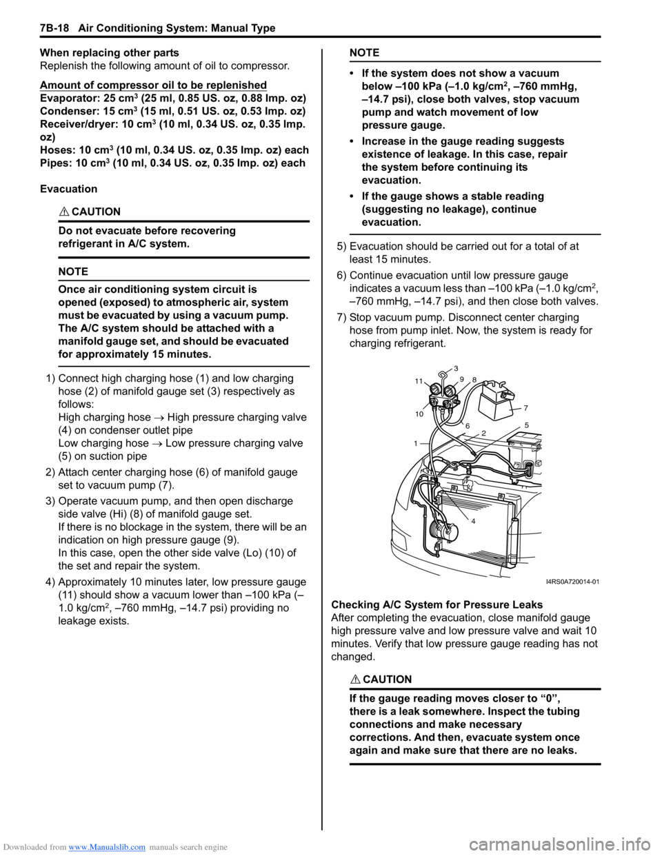
1) Connect high charging hose (1) and low charging hose (2) of manifold gauge set (3) respectively as
follows:
High charging hose → High pressure charging valve
(4) on condenser outlet pipe
Low charging hose → Low pressure charging valve
(5) on suction pipe
2) Attach center charging hose (6) of manifold gauge set to vacuum pump (7).
3) Operate vacuum pump, and then open discharge
side valve (Hi) (8) of manifold gauge set.
If there is no blockage in the system, there will be an
indication on high pressure gauge (9).
In this case, open the other side valve (Lo) (10) of
the set and repair the system.
4) Approximately 10 minutes later, low pressure gauge (11) should show a vacuum lower than –100 kPa (–
1.0 kg/cm
2, –760 mmHg, –14.7 psi) providing no
leakage exists.
NOTE
• If the system does not show a vacuum below –100 kPa (–1.0 kg/cm
2, –760 mmHg,
–14.7 psi), close both valves, stop vacuum
pump and watch movement of low
pressure gauge.
• Increase in the gauge reading suggests existence of leakage. In this case, repair
the system before continuing its
evacuation.
• If the gauge shows a stable reading (suggesting no leakage), continue
evacuation.
5) Evacuation should be carried out for a total of at least 15 minutes.
6) Continue evacuation until low pressure gauge indicates a vacuum less than –100 kPa (–1.0 kg/cm
2,
–760 mmHg, –14.7 psi), and then close both valves.
7) Stop vacuum pump. Disconnect center charging hose from pump inlet. No w, the system is ready for
charging refrigerant.
Checking A/C System for Pressure Leaks
After completing the evacuation, close manifold gauge
high pressure valve and low pressure valve and wait 10
minutes. Verify that low pressure gauge reading has not
changed.
CAUTION!
If the gauge reading moves closer to “0”,
there is a leak somewhere. Inspect the tubing
connections and make necessary
corrections. And then, evacuate system once
again and make sure that there are no leaks.
7 5
2
4
1
10
11
3
9 8
6
I4RS0A720014-01