2006 SUZUKI SWIFT fluid table
[x] Cancel search: fluid tablePage 805 of 1496

Downloaded from www.Manualslib.com manuals search engine Automatic Transmission/Transaxle: 5A-161
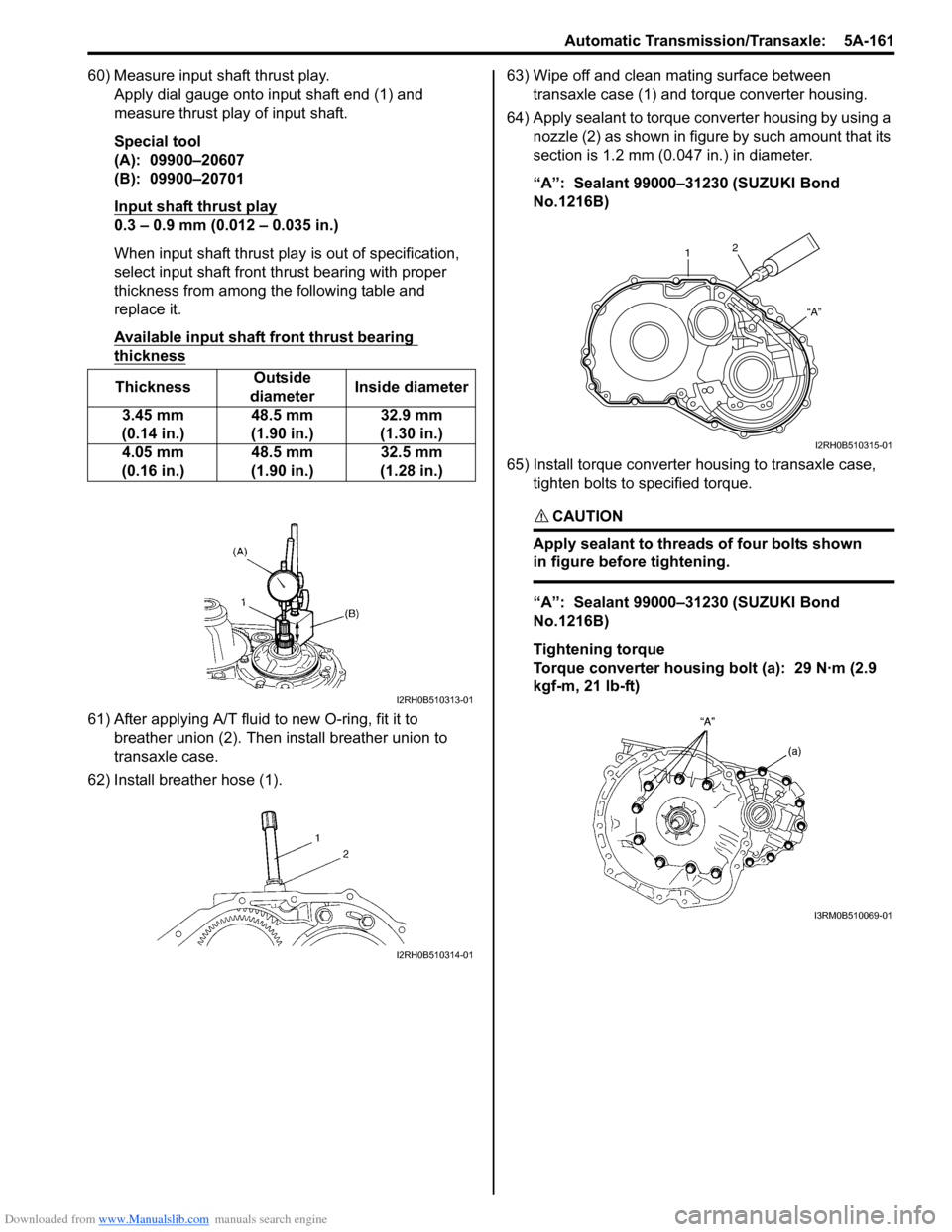
60) Measure input shaft thrust play.Apply dial gauge onto input shaft end (1) and
measure thrust play of input shaft.
Special tool
(A): 09900–20607
(B): 09900–20701
Input shaft thrust play
0.3 – 0.9 mm (0.012 – 0.035 in.)
When input shaft thrust play is out of specification,
select input shaft front th rust bearing with proper
thickness from among the following table and
replace it.
Available input shaft front thrust bearing
thickness
61) After applying A/T fluid to new O-ring, fit it to breather union (2). Then install breather union to
transaxle case.
62) Install breather hose (1). 63) Wipe off and clean mating surface between
transaxle case (1) and torque converter housing.
64) Apply sealant to torque converter housing by using a nozzle (2) as shown in figure by such amount that its
section is 1.2 mm (0.047 in.) in diameter.
“A”: Sealant 99000–31230 (SUZUKI Bond
No.1216B)
65) Install torque converter housing to transaxle case, tighten bolts to specified torque.
CAUTION!
Apply sealant to threads of four bolts shown
in figure before tightening.
“A”: Sealant 99000–31230 (SUZUKI Bond
No.1216B)
Tightening torque
Torque converter housing bolt (a): 29 N·m (2.9
kgf-m, 21 lb-ft)
Thickness
Outside
diameter Inside diameter
3.45 mm
(0.14 in.) 48.5 mm
(1.90 in.) 32.9 mm
(1.30 in.)
4.05 mm
(0.16 in.) 48.5 mm
(1.90 in.) 32.5 mm
(1.28 in.)
I2RH0B510313-01
I2RH0B510314-01
1 2
“A”
I2RH0B510315-01
I3RM0B510069-01
Page 1168 of 1496

Downloaded from www.Manualslib.com manuals search engine 9-ii Table of Contents
List of Connectors ........................................... 9A-103
C Connector .................................................... 9A-103
D Connector (M16A engine) ........................... 9A-104
E Connector .................................................... 9A-104
G Connector .................................................... 9A-106
J Connector ..................................................... 9A-108
K Connector .................................................... 9A-109
L Connector..................................................... 9A-109
M Connector (SPORT model) ......................... 9A-111
O Connector .................................................... 9A-111
R Connector .................................................... 9A-111
Lighting Systems .................................... 9B-1
Component Location ........... ................................9B-1
Lighting System Component s Location............... 9B-1
Interior Light System Location............................. 9B-2
Diagnostic Information and Procedures ............ 9B-2 Headlight Symptom Diagnosis ............................ 9B-2
Headlight Leveling System Symptom Diagnosis (If Equipped) ..................................... 9B-2
Turn Signal and Hazard Warning Light Symptom Diagnosis .......................................... 9B-3
Clearance, Tail and License Plate Light Symptom Diagnosis .......................................... 9B-3
Back-Up Light Symptom Diagnosis..................... 9B-4
Brake Light Symptom Diagnosis ......................... 9B-4
Front Fog Light Symptom Diagnosis (If Equipped) .......................................................... 9B-4
Interior Light Symptom Diagnosis ....................... 9B-5
Repair Instructions ..............................................9B-5 Headlight Housing Removal and Installation ...... 9B-5
Headlight Bulb Replacemen t............................... 9B-6
Headlight Aiming Adjustment with Screen .......... 9B-6
Headlight Switch (in Lighting Switch) Removal and Installation ................................... 9B-8
Headlight Switch (in Lighting Switch) Inspection .......................................................... 9B-8
Hazard Warning Switch Removal and Installation ......................................................... 9B-8
Hazard Warning Switch Inspection ..................... 9B-9
Brake Light Switch Inspection ............................. 9B-9
Turn Signal Light Switch (in Lighting Switch) Removal and Installation ................................... 9B-9
Turn Signal Light Switch (in Lighting Switch) Inspection .......................................................... 9B-9
Turn Signal and Hazard Warning Relay Removal and Installation ................................... 9B-9
Turn Signal and Hazard Warning Relay Inspection ........................................................ 9B-10
License Light Removal and Installation............. 9B-10
Front Fog Light Removal and Installation (If Equipped) ........................................................ 9B-11
Front Fog Light Bulb Replacement (If Equipped) ........................................................ 9B-11
Front Fog Light Switch Inspection (If Equipped) ........................................................ 9B-11
Front Fog Light Relay Inspection (If Equipped) ........................................................ 9B-11
Front Fog Light Aiming Adjustment with Screen (If Equipped) ....................................... 9B-12 Headlight Leveling Switch Inspection (If
Equipped) ........................................................ 9B-13
Headlight Leveling Actuator Inspection (If Equipped) ........................................................ 9B-13
Instrumentation / Driver Info. / Horn ...... 9C-1
Precautions ...........................................................9C-1 Precautions in Diagnosing Troubles for Combination Meter ............................................9C-1
General Description .............................................9C-1 CAN Communication System Description...........9C-1
Auto Volume Co ntrol System Description (If
Equipped) ..........................................................9C-3
Schematic and Routing Diagram ........................9C-4 Combination Meter Circuit Diagram ....................9C-4
Component Location ............ ...............................9C-6
Audio System Component Location ....................9C-6
Diagnostic Information and Procedures ............9C-6 Speedometer and VSS Symp tom Diagnosis ......9C-6
Tachometer Symptom Diagnosis ........................9C-6
Engine Coolant Temperature (ECT) Meter Symptom Diagnosis ..........................................9C-7
Fuel Meter Symptom Diagnosis ..........................9C-7
Low Fuel Warning Light Symptom Diagnosis .....9C-7
Oil Pressure Warning Light Symptom Diagnosis ..........................................................9C-8
Brake and Parking Brake Warning Light Symptom Diagnosis ..........................................9C-8
Seat Belt Reminder Light Symptom Diagnosis (If Equipped)......................................................9C-8
A/T Shift Position Indicator Symptom Diagnosis (A/T Model).......................................9C-9
Charge Warning Light Sy mptom Diagnosis ........9C-9
Main Beam (High Beam) Indicator Symptom Diagnosis ..........................................................9C-9
Warning Buzzer Circuit Sy mptom Diagnosis ....9C-10
Cigarette Lighter Symptom Diagnosis (If Equipped) ........................................................9C-10
Horn Symptom Diagnosis .................................9C-10
Information Display Symptom Diagnosis (If Equipped) ........................................................9C-11
Clock Symptom Diagnosis (If Equipped)...........9C-12
Audio System Symptom Diagnosis (If Equipped) ........................................................9C-12
Remote Audio Control Switch Symptom Diagnosis (If Equipped) ...................................9C-13
Navigation Symptom Diagnosis (If Equipped)...9C-14
Repair Instructions ............ ................................9C-14
Ignition Switch Removal and Installation...........9C-14
Ignition Switch Inspection..................................9C-14
Combination Meter Removal and Installation ...9C-15
Fuel Level Sensor Removal and Installation .....9C-15
Fuel Level Sensor Inspection ............................9C-15
Oil Pressure Switch Remova l and Installation ..9C-15
Oil Pressure Switch Inspec tion .........................9C-16
Engine Coolant Temperature (ECT) Sensor Inspection ........................................................9C-16
Brake Fluid Level Switch Inspection .................9C-16
Parking Brake Switch Inspec tion.......................9C-16
Page 1412 of 1496

Downloaded from www.Manualslib.com manuals search engine 10B-9 Body Electrical Control System:
Diagnostic Information and Procedures
BCM Self-Diagnosis FunctionS7RS0BA204001
• BCM monitors conditions of the system components and its circuit with ignition switch turned to ON position. When
an abnormality in the system oc curs, the area where that abnormality lies is stored in the memory of EEPROM in
BCM.
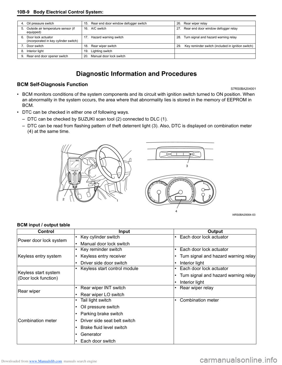
• DTC can be checked in either one of following ways. – DTC can be checked by SUZUKI scan tool (2) connected to DLC (1).
– DTC can be read from flashing pattern of theft deterrent light (3). Also, DTC is displayed on combination meter
(4) at the same time.
BCM input / output table
4. Oil pressure switch 15. Rear end door window defogger switch 26. Rear wiper relay
5. Outside air temperature sensor (if equipped) 16. A/C switch
27. Rear end door window defogger relay
6. Door lock actuator (incorporated in key cylinder switch) 17. Hazard warning switch
28. Turn signal and hazard warning relay
7. Door switch 18. Rear wiper switch 29. Key reminder switch (included in ignition switch)
8. Interior light 19. Lighting switch
9. Rear end door opener switch 20. Manual door lock switch
3
1
2
4I4RS0BA20004-03
Control
Input Output
Power door lock system • Key cylinder switch
• Manual door lock switch • Each door lock actuator
Keyless entry system • Key reminder switch
• Keyless entry receiver
• Driver side door switch • Each door lock actuator
• Turn signal and hazard warning relay
• Interior light
Keyless start system
(Door lock function) • Keyless start control module
• Each door lock actuator
• Turn signal and hazard warning relay
• Interior light
Rear wiper • Rear wiper INT switch
• Rear wiper LO switch • Rear wiper relay
Combination meter • Tail light switch
• Oil pressure switch
• Parking brake switch
• Driver side seat belt switch
• Brake fluid level switch
• Generator
• Each door switch • Combination meter