2006 SUZUKI SWIFT fluid table
[x] Cancel search: fluid tablePage 686 of 1496
Downloaded from www.Manualslib.com manuals search engine 5A-42 Automatic Transmission/Transaxle:
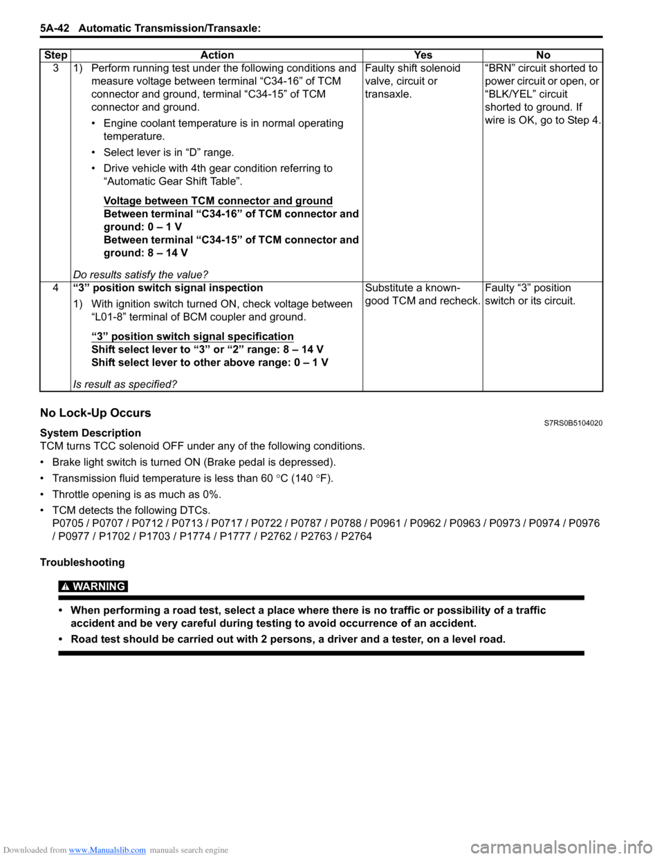
No Lock-Up OccursS7RS0B5104020
System Description
TCM turns TCC solenoid OFF under any of the following conditions.
• Brake light switch is turned ON (Brake pedal is depressed).
• Transmission fluid temperat ure is less than 60 °C (140 °F).
• Throttle opening is as much as 0%.
• TCM detects the following DTCs. P0705 / P0707 / P0712 / P0713 / P0717 / P0722 / P0787 / P0788 / P0961 / P0962 / P0963 / P0973 / P0974 / P0976
/ P0977 / P1702 / P1703 / P1774 / P1777 / P2762 / P2763 / P2764
Troubleshooting
WARNING!
• When performing a road test, select a place where there is no traffic or possibility of a traffic accident and be very careful during testing to avoid occurrence of an accident.
• Road test should be carried out with 2 persons, a driver and a tester, on a level road.
3 1) Perform running test under the following conditions and measure voltage between terminal “C34-16” of TCM
connector and ground, terminal “C34-15” of TCM
connector and ground.
• Engine coolant temperature is in normal operating temperature.
• Select lever is in “D” range.
• Drive vehicle with 4th gear condition referring to “Automatic Gear Shift Table”.
Voltage between TCM connector and ground
Between terminal “C34-16” of TCM connector and
ground: 0 – 1 V
Between terminal “C34-15” of TCM connector and
ground: 8 – 14 V
Do results satisfy the value? Faulty shift solenoid
valve, circuit or
transaxle.
“BRN” circuit shorted to
power circuit or open, or
“BLK/YEL” circuit
shorted to ground. If
wire is OK, go to Step 4.
4 “3” position switch signal inspection
1) With ignition switch turned ON, check voltage between
“L01-8” terminal of BCM coupler and ground.
“3” position switch signal specification
Shift select lever to “3” or “2” range: 8 – 14 V
Shift select lever to other above range: 0 – 1 V
Is result as specified? Substitute a known-
good TCM and recheck.
Faulty “3” position
switch or its circuit.
Step Action Yes No
Page 692 of 1496
Downloaded from www.Manualslib.com manuals search engine 5A-48 Automatic Transmission/Transaxle:
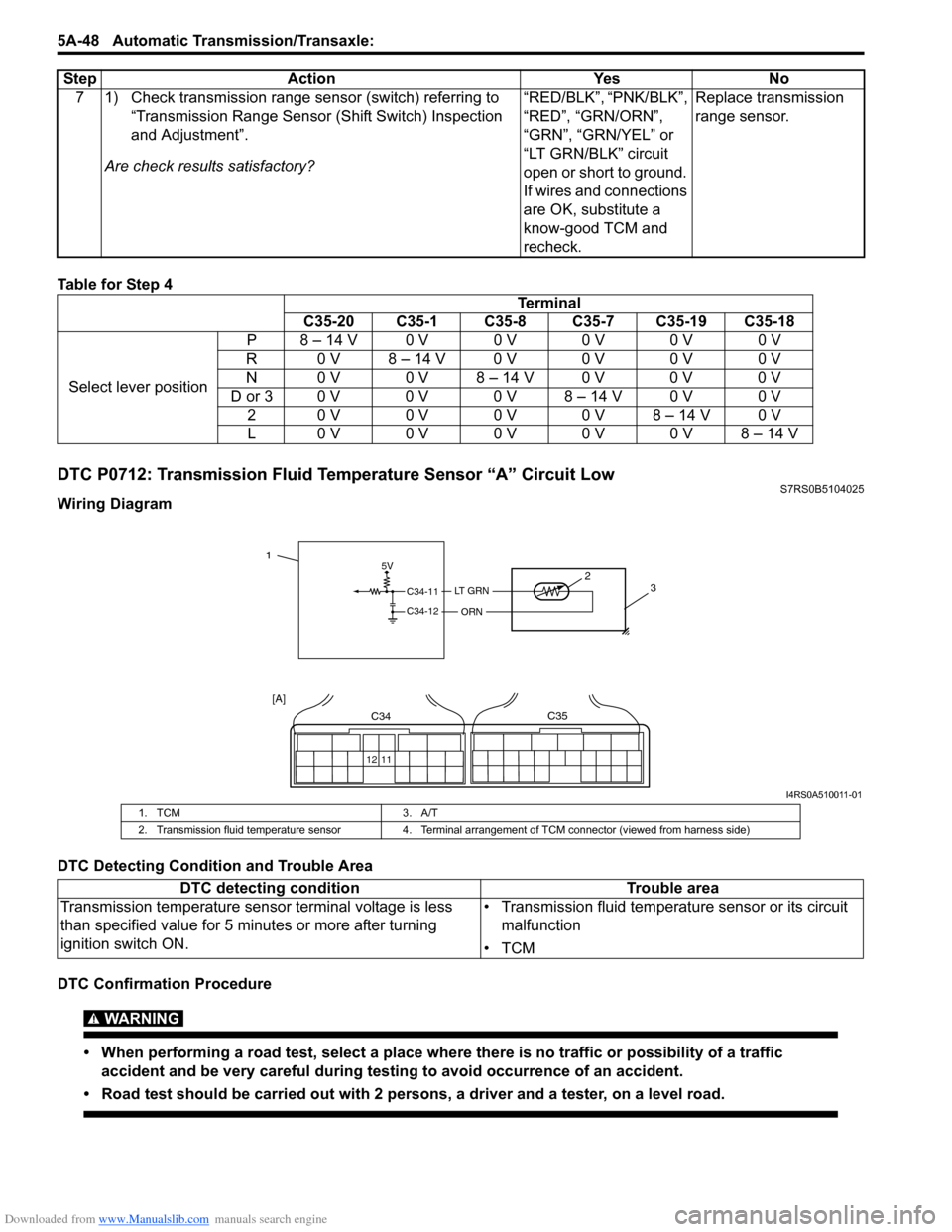
Table for Step 4
DTC P0712: Transmission Fluid Temperature Sensor “A” Circuit LowS7RS0B5104025
Wiring Diagram
DTC Detecting Condition and Trouble Area
DTC Confirmation Procedure
WARNING!
• When performing a road test, select a place where there is no traffic or possibility of a traffic
accident and be very careful during testing to avoid occurrence of an accident.
• Road test should be carried out with 2 persons, a driver and a tester, on a level road.
7 1) Check transmission range sensor (switch) referring to “Transmission Range Sensor (Shift Switch) Inspection
and Adjustment”.
Are check results satisfactory? “RED/BLK”, “PNK/BLK”,
“RED”, “GRN/ORN”,
“GRN”, “GRN/YEL” or
“LT GRN/BLK” circuit
open or short to ground.
If wires and connections
are OK, substitute a
know-good TCM and
recheck.Replace transmission
range sensor.
Step Action Yes No
Terminal
C35-20 C35-1 C35-8 C35-7 C35-19 C35-18
Select lever position P8 – 14 V0 V0 V0 V0 V0 V
R 0 V 8 – 14 V 0 V 0 V 0 V 0 V
N 0 V 0 V 8 – 14 V 0 V 0 V 0 V
D or 3 0 V 0 V 0 V 8 – 14 V 0 V 0 V 20 V0 V0 V0 V8 – 14 V0 V
L0 V0 V0 V0 V0 V8 – 14 V
5V
C34-11
C34-12
LT GRN
ORN
2 3
12 11
C34C35
[A]
1
I4RS0A510011-01
1. TCM 3. A/T
2. Transmission fluid temperature sensor 4. Terminal arrangement of TCM connector (viewed from harness side)
DTC detecting condition Trouble area
Transmission temperature sensor terminal voltage is less
than specified value for 5 minutes or more after turning
ignition switch ON. • Transmission fluid temperature sensor or its circuit
malfunction
•TCM
Page 719 of 1496
Downloaded from www.Manualslib.com manuals search engine Automatic Transmission/Transaxle: 5A-75
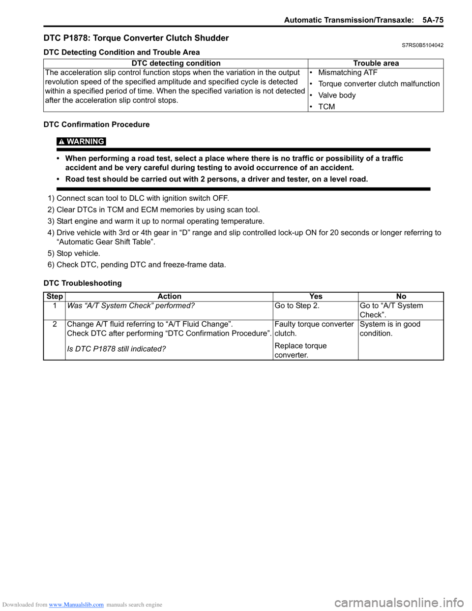
DTC P1878: Torque Converter Clutch ShudderS7RS0B5104042
DTC Detecting Condition and Trouble Area
DTC Confirmation Procedure
WARNING!
• When performing a road test, select a place where there is no traffic or possibility of a traffic accident and be very careful during testing to avoid occurrence of an accident.
• Road test should be carried out with 2 persons, a driver and tester, on a level road.
1) Connect scan tool to DLC with ignition switch OFF.
2) Clear DTCs in TCM and ECM memories by using scan tool.
3) Start engine and warm it up to normal operating temperature.
4) Drive vehicle with 3rd or 4th gear in “D” range and slip c ontrolled lock-up ON for 20 seconds or longer referring to
“Automatic Gear Shift Table”.
5) Stop vehicle.
6) Check DTC, pending DTC and freeze-frame data.
DTC Troubleshooting DTC detecting condition
Trouble area
The acceleration slip control function stops when the variation in the output
revolution speed of the specified amp litude and specified cycle is detected
within a specified period of time. When t he specified variation is not detected
after the acceleration slip control stops. • Mismatching ATF
• Torque converter clutch malfunction
• Valve body
•TCM
Step
Action YesNo
1 Was “A/T System Check” performed? Go to Step 2.Go to “A/T System
Check”.
2 Change A/T fluid referring to “A/T Fluid Change”. Check DTC after performing “DTC Confirmation Procedure”.
Is DTC P1878 still indicated? Faulty torque converter
clutch.
Replace torque
converter.System is in good
condition.
Page 770 of 1496

Downloaded from www.Manualslib.com manuals search engine 5A-126 Automatic Transmission/Transaxle:
Reassembly
Reverse disassembly procedure for assembly, noting the
following points.
• Use new seal ring and O-ring. Apply A/T fluid before installation.
• Do not damage direct clutch return spring subassembly (1) and piston by pressing in direct
clutch return spring subassembly passing through its
original installing position over 0.7 mm (0.027 in.).
Special tool
(A): 09926–98310
• Apply A/T fluid to direct cl utch separator plates (4),
discs (3) and retaining plate (2).
• Install direct clutch separator plates (4), discs (3), retaining plate (2) and snap ring (1) to input shaft
subassembly.
• Install plate snap ring so that its both ends would be positioned in correct locations as shown in figure. • After assembly, measure direct clutch piston stroke.
Special tool
(A): 09900–20607
(B): 09900–20701
Direct clutch piston stroke
0.4 – 0.7 mm (0.016 – 0.027 in.)
When piston stroke is out of specification, select direct
clutch retaining plate with suitable thickness from
among the following table and replace it.
Available direct clutch retaining plate thickness
I2RH0B510168-01
I2RH0B510169-01
[A]: Correct [B]: Incorrect
ThicknessIdentification mark
3.0 mm (0.118 in.) 1
3.2 mm (0.126 in.) 2
3.4 mm (0.134 in.) 3
2.8 mm (0.110 in.) 4
1. Direct clutch assembly 3. Oil hole
2. Oil pump assembly
I2RH0B510170-01
I2RH0B510171-01
Page 776 of 1496

Downloaded from www.Manualslib.com manuals search engine 5A-132 Automatic Transmission/Transaxle:
• Measure forward clutch piston stroke in the same manner as “Forward and Reverse Clutch Assembly
Preliminary Check”.
When piston stroke is out of specification, select
forward clutch retaining plate with proper thickness
from among the following table and replace it.
Special tool
(A): 09900–20607
(B): 09900–20701
(C): 09952–06020
Forward clutch piston stroke
1.30 – 1.50 mm (0.051 – 0.059 in.)
Available forward clutch retaining plate thickness
• Install reverse clutch cushion plate (1) in correct direction as shown in figure.
• Apply A/T fluid to reverse clutch cushion plate (1),
reverse clutch separator plate (2), discs (3) and
retaining plate (4).
• Install reverse clutch cushio n plate (1), reverse clutch
separator plate (2), discs (3), retaining plate (4) and
then snap ring (5) to inte rmediate shaft subassembly. • Install reverse clutch plate snap ring so that its both
ends would be positioned in correct locations as
shown in figure.
• Measure reverse clutch piston stroke in the same manner as “Forward and Reverse Clutch Assembly
Preliminary Check”.
When piston stroke is out of specification, select
reverse clutch retaining plate with proper thickness
from among the following table and replace it.
Special tool
(A): 09900–20607
(B): 09900–20701
Reverse clutch piston stroke
1.20 – 1.60 mm (0.047 – 0.063 in.)
Available reverse clutch retaining plate thickness
Thickness Identification mark
3.0 mm (0.118 in.) 1
3.1 mm (0.122 in.) 5
3.2 mm (0.126 in.) 2
3.3 mm (0.130 in.) 6
3.4 mm (0.134 in.) 3
3.5 mm (0.138 in.) 7
3.6 mm (0.142 in.) 4
1. Oil hole
I2RH0B510177-02
I3RM0B510062-01
[A]: Correct[B]: Incorrect
ThicknessIdentification mark
3.0 mm (0.118 in.) 1
3.2 mm (0.126 in.) 2
3.4 mm (0.134 in.) 3
3.6 mm (0.142 in.) 4
I2RH0B510190-01
I2RH0B510191-01
Page 792 of 1496
Downloaded from www.Manualslib.com manuals search engine 5A-148 Automatic Transmission/Transaxle:
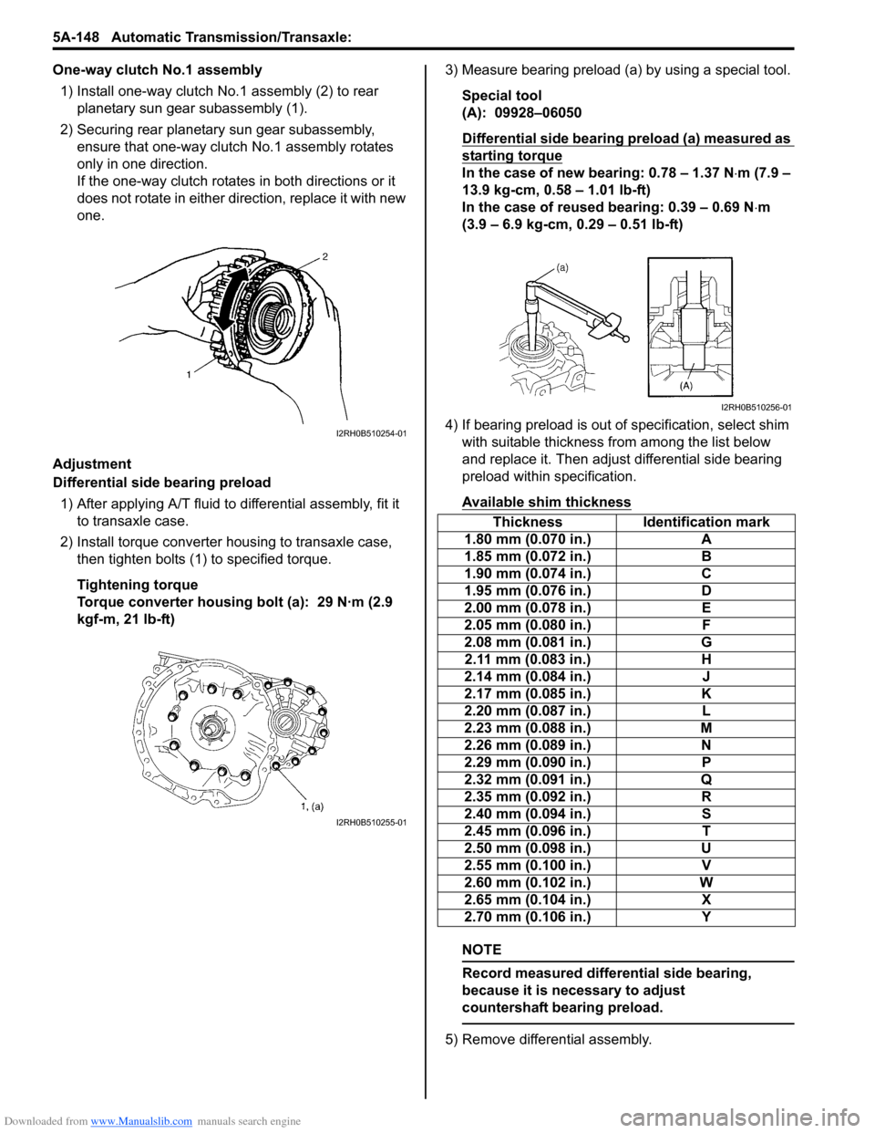
One-way clutch No.1 assembly1) Install one-way clutch No.1 assembly (2) to rear planetary sun gear subassembly (1).
2) Securing rear planetary sun gear subassembly, ensure that one-way clutch No.1 assembly rotates
only in one direction.
If the one-way clutch rotates in both directions or it
does not rotate in either direction, replace it with new
one.
Adjustment
Differential side bearing preload 1) After applying A/T fluid to differential assembly, fit it to transaxle case.
2) Install torque converter housing to transaxle case, then tighten bolts (1) to specified torque.
Tightening torque
Torque converter housing bolt (a): 29 N·m (2.9
kgf-m, 21 lb-ft) 3) Measure bearing preload (a) by using a special tool.
Special tool
(A): 09928–06050
Differential side bearing preload (a) measured as
starting torque
In the case of new bearing: 0.78 – 1.37 N ⋅m (7.9 –
13.9 kg-cm, 0.58 – 1.01 lb-ft)
In the case of reused bearing: 0.39 – 0.69 N ⋅m
(3.9 – 6.9 kg-cm, 0.29 – 0.51 lb-ft)
4) If bearing preload is out of specification, select shim with suitable thickness from among the list below
and replace it. Then adjust differential side bearing
preload within specification.
Available shim thickness
NOTE
Record measured differential side bearing,
because it is necessary to adjust
countershaft bearing preload.
5) Remove differential assembly.
I2RH0B510254-01
I2RH0B510255-01
Thickness Identification mark
1.80 mm (0.070 in.) A
1.85 mm (0.072 in.) B
1.90 mm (0.074 in.) C
1.95 mm (0.076 in.) D
2.00 mm (0.078 in.) E
2.05 mm (0.080 in.) F
2.08 mm (0.081 in.) G
2.11 mm (0.083 in.) H
2.14 mm (0.084 in.) J
2.17 mm (0.085 in.) K
2.20 mm (0.087 in.) L
2.23 mm (0.088 in.) M
2.26 mm (0.089 in.) N
2.29 mm (0.090 in.) P
2.32 mm (0.091 in.) Q
2.35 mm (0.092 in.) R
2.40 mm (0.094 in.) S
2.45 mm (0.096 in.) T
2.50 mm (0.098 in.) U
2.55 mm (0.100 in.) V
2.60 mm (0.102 in.) W
2.65 mm (0.104 in.) X
2.70 mm (0.106 in.) Y
I2RH0B510256-01
Page 793 of 1496
Downloaded from www.Manualslib.com manuals search engine Automatic Transmission/Transaxle: 5A-149
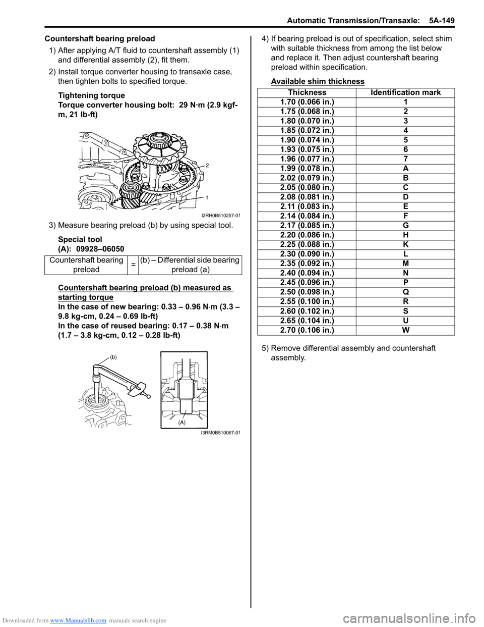
Countershaft bearing preload1) After applying A/T fluid to countershaft assembly (1) and differential assembly (2), fit them.
2) Install torque converter housing to transaxle case, then tighten bolts to specified torque.
Tightening torque
Torque converter housing bolt: 29 N·m (2.9 kgf-
m, 21 lb-ft)
3) Measure bearing preload (b) by using special tool. Special tool
(A): 09928–06050
Countershaft bearing preload (b) measured as
starting torque
In the case of new bearing: 0.33 – 0.96 N⋅ m (3.3 –
9.8 kg-cm, 0.24 – 0.69 lb-ft)
In the case of reused bearing: 0.17 – 0.38 N ⋅m
(1.7 – 3.8 kg-cm, 0.12 – 0.28 lb-ft) 4) If bearing preload is out of specification, select shim
with suitable thickness from among the list below
and replace it. Then adjust countershaft bearing
preload within specification.
Available shim thickness
5) Remove differential assembly and countershaft assembly.
Countershaft bearing
preload =(b) – Differential side bearing
preload (a)
I2RH0B510257-01
I3RM0B510067-01
Thickness Identification mark
1.70 (0.066 in.) 1
1.75 (0.068 in.) 2
1.80 (0.070 in.) 3
1.85 (0.072 in.) 4
1.90 (0.074 in.) 5
1.93 (0.075 in.) 6
1.96 (0.077 in.) 7
1.99 (0.078 in.) A
2.02 (0.079 in.) B
2.05 (0.080 in.) C
2.08 (0.081 in.) D
2.11 (0.083 in.) E
2.14 (0.084 in.) F
2.17 (0.085 in.) G
2.20 (0.086 in.) H
2.25 (0.088 in.) K
2.30 (0.090 in.) L
2.35 (0.092 in.) M
2.40 (0.094 in.) N
2.45 (0.096 in.) P
2.50 (0.098 in.) Q
2.55 (0.100 in.) R
2.60 (0.102 in.) S
2.65 (0.104 in.) U
2.70 (0.106 in.) W
Page 802 of 1496
Downloaded from www.Manualslib.com manuals search engine 5A-158 Automatic Transmission/Transaxle:
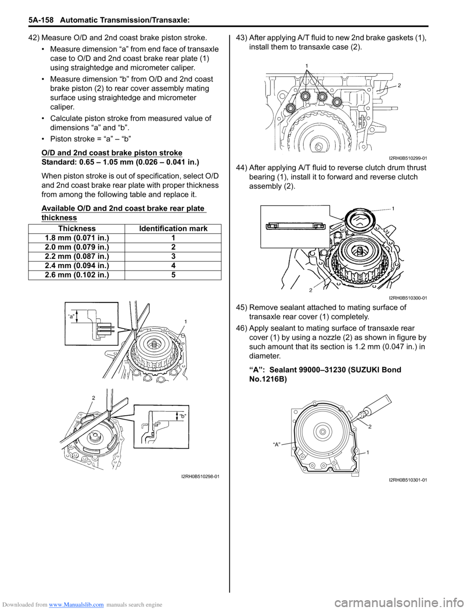
42) Measure O/D and 2nd coast brake piston stroke.• Measure dimension “a” from end face of transaxle case to O/D and 2nd coast brake rear plate (1)
using straightedge and micrometer caliper.
• Measure dimension “b” from O/D and 2nd coast brake piston (2) to rear cover assembly mating
surface using straightedge and micrometer
caliper.
• Calculate piston stroke from measured value of dimensions “a” and “b”.
• Piston stroke = “a” – “b”
O/D and 2nd coast brake piston stroke
Standard: 0.65 – 1.05 mm (0.026 – 0.041 in.)
When piston stroke is out of specification, select O/D
and 2nd coast brake rear plate with proper thickness
from among the following table and replace it.
Available O/D and 2nd coast brake rear plate
thickness
43) After applying A/T fluid to new 2nd brake gaskets (1), install them to transaxle case (2).
44) After applying A/T fluid to reverse clutch drum thrust bearing (1), install it to forward and reverse clutch
assembly (2).
45) Remove sealant attached to mating surface of transaxle rear cover (1) completely.
46) Apply sealant to mating surface of transaxle rear cover (1) by using a nozzle (2) as shown in figure by
such amount that its section is 1.2 mm (0.047 in.) in
diameter.
“A”: Sealant 99000–31230 (SUZUKI Bond
No.1216B)
Thickness Identification mark
1.8 mm (0.071 in.) 1
2.0 mm (0.079 in.) 2
2.2 mm (0.087 in.) 3
2.4 mm (0.094 in.) 4
2.6 mm (0.102 in.) 5
I2RH0B510298-01
I2RH0B510299-01
I2RH0B510300-01
“A” 2
1
I2RH0B510301-01