Page 281 of 1496

Downloaded from www.Manualslib.com manuals search engine Engine Electrical Devices: 1C-9
CKP Sensor Removal and InstallationS7RS0B1306014
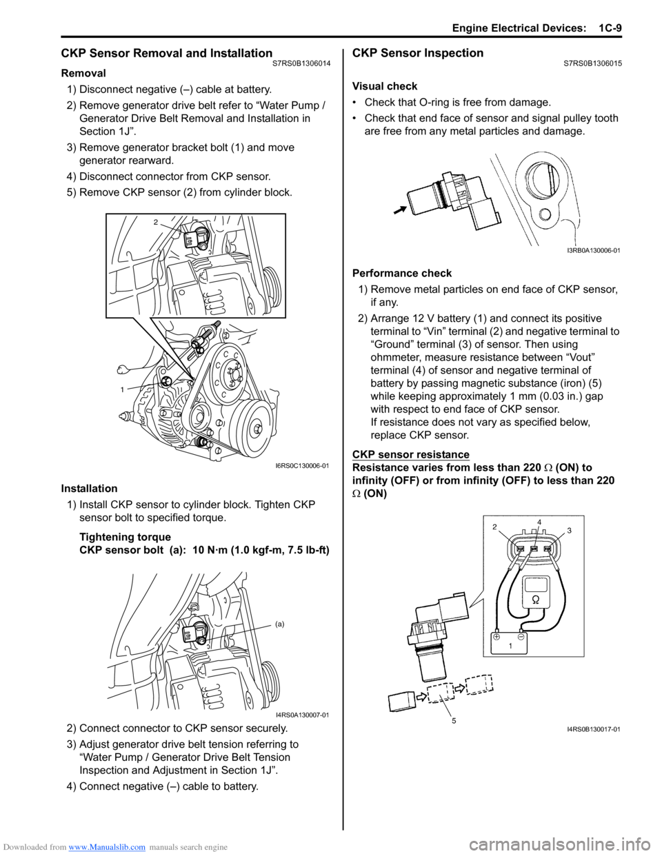
Removal1) Disconnect negative (–) cable at battery.
2) Remove generator drive belt refer to “Water Pump / Generator Drive Belt Remo val and Installation in
Section 1J”.
3) Remove generator bracket bolt (1) and move generator rearward.
4) Disconnect connector from CKP sensor.
5) Remove CKP sensor (2) from cylinder block.
Installation 1) Install CKP sensor to cylinder block. Tighten CKP sensor bolt to specified torque.
Tightening torque
CKP sensor bolt (a): 10 N·m (1.0 kgf-m, 7.5 lb-ft)
2) Connect connector to CKP sensor securely.
3) Adjust generator drive belt tension referring to “Water Pump / Generator Drive Belt Tension
Inspection and Adjustment in Section 1J”.
4) Connect negative (–) cable to battery.
CKP Sensor InspectionS7RS0B1306015
Visual check
• Check that O-ring is free from damage.
• Check that end face of sensor and signal pulley tooth are free from any metal particles and damage.
Performance check 1) Remove metal particles on end face of CKP sensor, if any.
2) Arrange 12 V battery (1) and connect its positive terminal to “Vin” terminal (2) and negative terminal to
“Ground” terminal (3) of sensor. Then using
ohmmeter, measure resistance between “Vout”
terminal (4) of sensor and negative terminal of
battery by passing magnetic substance (iron) (5)
while keeping approximately 1 mm (0.03 in.) gap
with respect to end face of CKP sensor.
If resistance does not vary as specified below,
replace CKP sensor.
CKP sensor resistance
Resistance varies from less than 220 Ω (ON) to
infinity (OFF) or from infinity (OFF) to less than 220
Ω (ON)
2
1
I6RS0C130006-01
(a)
I4RS0A130007-01
I3RB0A130006-01
I4RS0B130017-01
Page 306 of 1496

Downloaded from www.Manualslib.com manuals search engine 1D-21 Engine Mechanical:
Timing Chain Cover Removal and InstallationS7RS0B1406013
CAUTION!
• Keep working table, tools and hands clean while overhauling.
• Use special care to handle aluminum parts so as not to damage them.
• Do not expose removed parts to dust. Keep them always clean.
Removal
1) Remove engine assembly from vehicle referring to “Engine Assembly Removal and Installation”.
2) Remove water pump / generator drive belt referring to “Water Pump / Generator Drive Belt Removal and
Installation in Section 1J”.
3) Remove crankshaft pulley bolt. To lock crankshaft pulley (1), use special tool with it
as shown in figure.
Special tool
(A): 09917–68221
4) Remove crankshaft pulley (1). If it is hard to remove, use special tools as shown in
figure.
Special tool
(A): 09944–36011
(B): 09926–58010 5) Remove cylinder head cove
r referring to “Cylinder
Head Cover Removal and Installation”.
6) Remove oil pan referring to “Oil Pan and Oil Pump
Strainer Removal and Inst allation in Section 1E”.
7) Remove water pump pulley.
8) Remove A/C bracket from cylinder block.
9) Remove oil gallery pipe s No.2 (1) and No.3 (2).
10) Remove cap (1) from timing chain cover (2). 11) Remove timing chain cover (2).
12) Remove oil control valve from timing chain cover referring to “Oil Cont rol Valve Removal and
Installation”.
10. Copper washer :30 N⋅m (3.0 kgf-m, 22.0 lb-ft)
11. Oil gallery pipe No.1 bolt : 150 N⋅m (15.0 kgf-m, 108.5 lb-ft)
12. Oil gallery pipe No.2 : Do not reuse.
I2RH0B140051-01
I2RH0B140052-01
1
2
I3RH0B140021-01
1 2
I3RH0B140022-01
Page 308 of 1496

Downloaded from www.Manualslib.com manuals search engine 1D-23 Engine Mechanical:
8) Install new O-ring (1) to oil gallery pipes No.2 (2) and
No.3 (3).
9) Install oil gallery pipes No.2 and No.3 to cylinder
head (4) and timing chain cover (5).
Tighten bolts to specified torque.
Tightening torque
Oil gallery pipe No.2 and No.3 bolt (a): 11 N·m (
1.1 kgf-m, 8.0 lb-ft)
10) Install water pump pulley. 11) Install cylinder head cover referring to “Cylinder Head Cover Removal and Installation”.
12) Install oil pan referring to “Oil Pan and Oil Pump
Strainer Removal and Installation in Section 1E”.
13) Install crankshaft pulley (1). Tighten bolt (2) to specified torque. To lock crankshaft pulley, use
special tool with it as shown in figure.
Special tool
(A): 09917–68221
Tightening torque
Crankshaft pulley bolt (a): 150 N·m (15.0 kgf-m,
108.5 lb-ft)
14) Install engine assembly to vehicle referring to “Engine Assembly Removal and Installation”.
Timing Chain Cover InspectionS7RS0B1406014
Oil Seal
Check oil seal lip for fault or other damage. Replace as
necessary. Timing Chain Cover
Inspect strainer (1) of oil passage for driving intake cam
timing sprocket assembly (VVT actuator).
If clog or foreign matter exists, clean strainer.
Oil Control Valve Removal and InstallationS7RS0B1406015
Removal
Remove oil gallery pipe No.1
(1) and oil control valve (2)
from timing chain cover (3).
Installation
1) Install new O-ring (4) to oil control valve.
2) Install oil control valve to timing chain cover. Tighten nuts to specification.
Tightening torque
Oil control valve mounting nut (a): 11 N·m (1.1
kgf-m, 8.0 lb-ft)
3) Install oil gallery pipe No .1 with new copper washers
(5) to timing chain cover.
Tighten bolts to specification.
Tightening torque
Oil gallery pipe No.1 bolt (b): 30 N·m (3.0 kgf-m,
21.5 lb-ft)
(a)
(a) 1
2
3
4
5
I3RH0B140027-01
I2RH0B140056-01
1
I3RH0B140028-01
1
5
(b) 3
(a)
2 4
5
I3RM0A140027-01
Page 374 of 1496

Downloaded from www.Manualslib.com manuals search engine 1F-11 Engine Cooling System:
Water Pump Removal and InstallationS7RS0B1606014
Removal1) Disconnect negative cable at battery.
2) Drain coolant.
3) Remove water pump / generator drive belt referring to “Water Pump / Generator Drive Belt Removal and
Installation in Section 1J”.
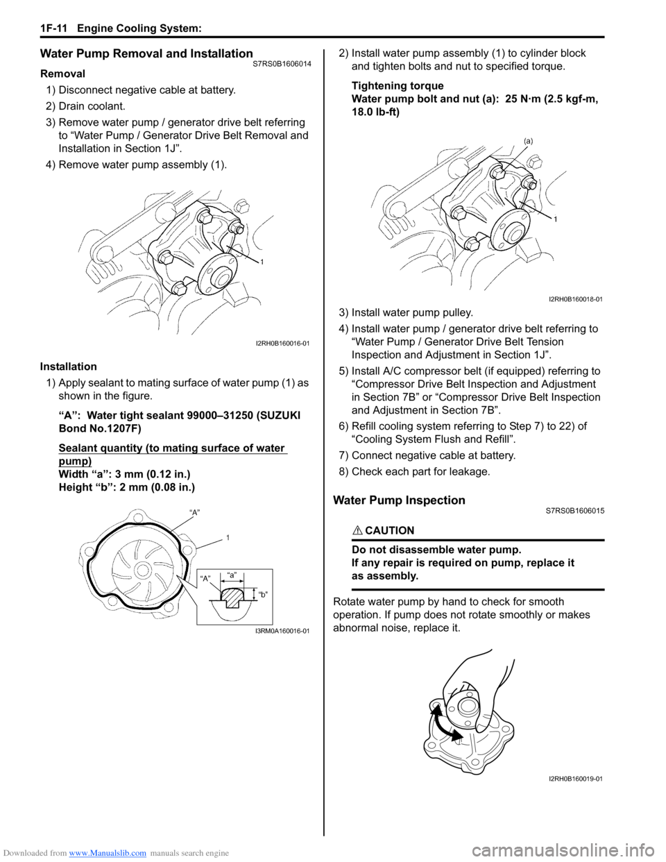
4) Remove water pump assembly (1).
Installation 1) Apply sealant to mating surface of water pump (1) as shown in the figure.
“A”: Water tight sealant 99000–31250 (SUZUKI
Bond No.1207F)
Sealant quantity (to mating surface of water
pump)
Width “a”: 3 mm (0.12 in.)
Height “b”: 2 mm (0.08 in.) 2) Install water pump assemb
ly (1) to cylinder block
and tighten bolts and nut to specified torque.
Tightening torque
Water pump bolt and nut (a): 25 N·m (2.5 kgf-m,
18.0 lb-ft)
3) Install water pump pulley.
4) Install water pump / generator drive belt referring to “Water Pump / Generator Drive Belt Tension
Inspection and Adjustment in Section 1J”.
5) Install A/C compressor belt (if equipped) referring to “Compressor Drive Belt Inspection and Adjustment
in Section 7B” or “Compressor Drive Belt Inspection
and Adjustment in Section 7B”.
6) Refill cooling system referri ng to Step 7) to 22) of
“Cooling System Flush and Refill”.
7) Connect negative cable at battery.
8) Check each part for leakage.
Water Pump InspectionS7RS0B1606015
CAUTION!
Do not disassemble water pump.
If any repair is requir ed on pump, replace it
as assembly.
Rotate water pump by hand to check for smooth
operation. If pump does not rotate smoothly or makes
abnormal noise, replace it.
I2RH0B160016-01
I3RM0A160016-01
I2RH0B160018-01
I2RH0B160019-01