2006 SUZUKI SWIFT P 0037
[x] Cancel search: P 0037Page 296 of 1496

Downloaded from www.Manualslib.com manuals search engine 1D-11 Engine Mechanical:
2) Remove oil, old sealant, and dust from sealing surfaces on cylinder head and cover. After cleaning,
apply sealant “A” to the following point.
• Cylinder head cover gasket (1) sealing surface area (2) as shown.
“A”: Water tight sealant 99000–31250
(SUZUKI Bond No.1207F)
• Timing chain cover (1) and cylinder head (2) mating surface as shown.
“A”: Water tight sealant 99000–31250
(SUZUKI Bond No.1207F) 3) Install cylinder head cover to cylinder head.
NOTE
When installing cylinder head cover, use care
so that cylinder head cover gasket or spark
plug hole gaskets will not get out of place or
fall off.
4) Tighten cylinder head cover bolts as follows.
a) Tighten cylinder head cover bolts to 3 N ⋅m (0.3
kgf-m, 2.5 lb-ft) according to numerical order (“1”
through “7”) as shown in figure.
b) In the same manner as in Step, a) tighten them
to 5 N ⋅m (0.5 kgf-m, 4.0 lb-ft).
c) Retighten them by turning through 8 N ⋅m (0.8
kgf-m, 6.0 lb-ft) in same manner as Step a).
Tightening torque
Cylinder head cover bolt (a): Tighten 3 N ⋅m (0.3
kgf-m, 2.5 lb-ft), 5 N ⋅m (0.5 kgf-m, 4.0 lb-ft) and 8
N ⋅m (0.8 kgf-m, 6.0 lb-ft) by the specified
procedure
5) Connect PCV hose (2) to PCV valve (3).
6) Connect breather hose (4).
7) Install oil level gauge (1).
8) Install wire harness clamp to cylinder head cover.
9) Install ignition coil assemb lies with high-tension cord
referring to “Ignit ion Coil Assembly (Including ignitor)
Removal and Installati on in Section 1H”.
10) Connect ignition coil couplers and clamp harness securely.
11) Install cylinder head upper cover.
12) Install air cleaner case and resonator.
13) Connect negative cable at battery.
I2RH0B140036-01
I2RH0B140037-01
I3RH0B140016-01
Page 443 of 1496
Downloaded from www.Manualslib.com manuals search engine Front Suspension: 2B-10
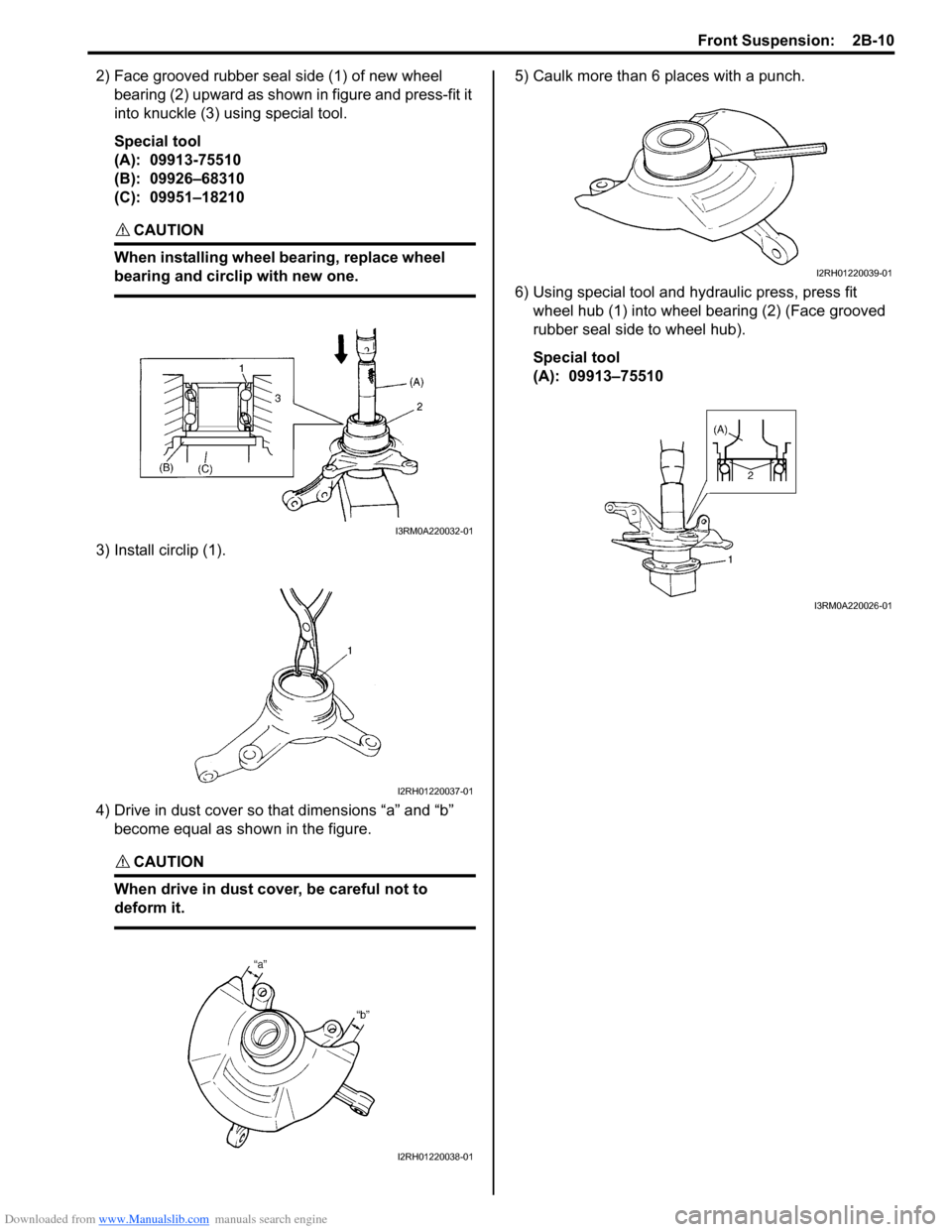
2) Face grooved rubber seal side (1) of new wheel bearing (2) upward as shown in figure and press-fit it
into knuckle (3) using special tool.
Special tool
(A): 09913-75510
(B): 09926–68310
(C): 09951–18210
CAUTION!
When installing wheel bearing, replace wheel
bearing and circlip with new one.
3) Install circlip (1).
4) Drive in dust cover so that dimensions “a” and “b” become equal as shown in the figure.
CAUTION!
When drive in dust cover, be careful not to
deform it.
5) Caulk more than 6 places with a punch.
6) Using special tool and hydraulic press, press fit
wheel hub (1) into wheel bearing (2) (Face grooved
rubber seal side to wheel hub).
Special tool
(A): 09913–75510
I3RM0A220032-01
I2RH01220037-01
I2RH01220038-01
I2RH01220039-01
I3RM0A220026-01
Page 572 of 1496
Downloaded from www.Manualslib.com manuals search engine 4E-33 ABS:
Rear Wheel Speed Sensor Removal and
Installation
S7RS0B4506008
Removal1) Disconnect negative (–) cable from battery.
2) Remove quarter inner trim to brake referring to “Floor Carpet Removal a nd Installation in Section
9H”.
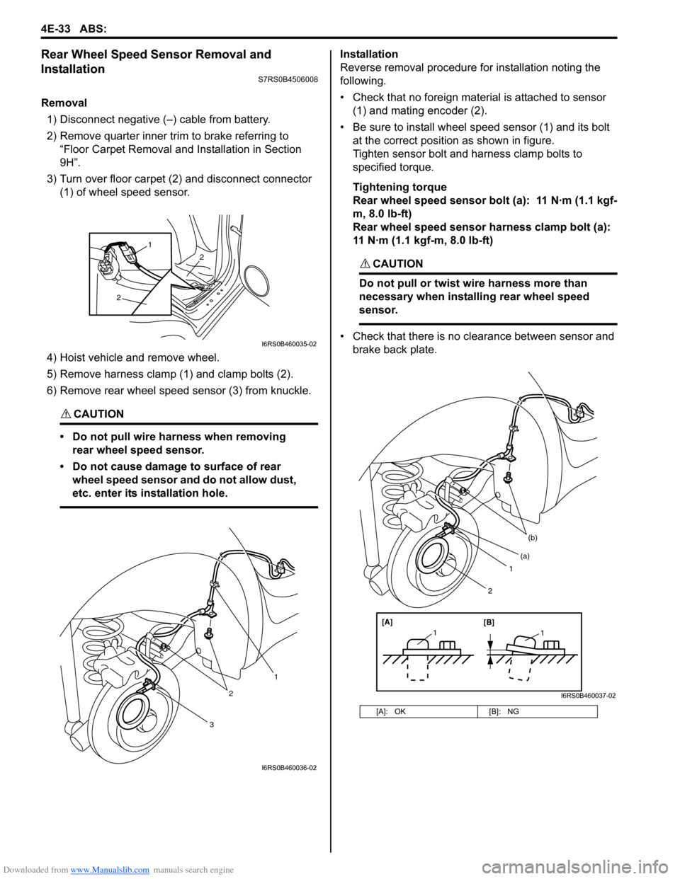
3) Turn over floor carpet (2) and disconnect connector (1) of wheel speed sensor.
4) Hoist vehicle and remove wheel.
5) Remove harness clamp (1) and clamp bolts (2).
6) Remove rear wheel speed sensor (3) from knuckle.
CAUTION!
• Do not pull wire harness when removing rear wheel speed sensor.
• Do not cause damage to surface of rear wheel speed sensor and do not allow dust,
etc. enter its installation hole.
Installation
Reverse removal procedure for installation noting the
following.
• Check that no foreign material is attached to sensor (1) and mating encoder (2).
• Be sure to install wheel speed sensor (1) and its bolt at the correct position as shown in figure.
Tighten sensor bolt and harness clamp bolts to
specified torque.
Tightening torque
Rear wheel speed sensor bolt (a): 11 N·m (1.1 kgf-
m, 8.0 lb-ft)
Rear wheel speed sensor harness clamp bolt (a):
11 N·m (1.1 kgf-m, 8.0 lb-ft)
CAUTION!
Do not pull or twist wire harness more than
necessary when installing rear wheel speed
sensor.
• Check that there is no clearance between sensor and brake back plate.
2
2
1
I6RS0B460035-02
3
2
1
I6RS0B460036-02
[A]: OK [B]: NG
1
(b)
[A][B]
11
(a)
2
I6RS0B460037-02
Page 634 of 1496
Downloaded from www.Manualslib.com manuals search engine 4F-60 Electronic Stability Program:
4) Hoist vehicle and remove wheel.
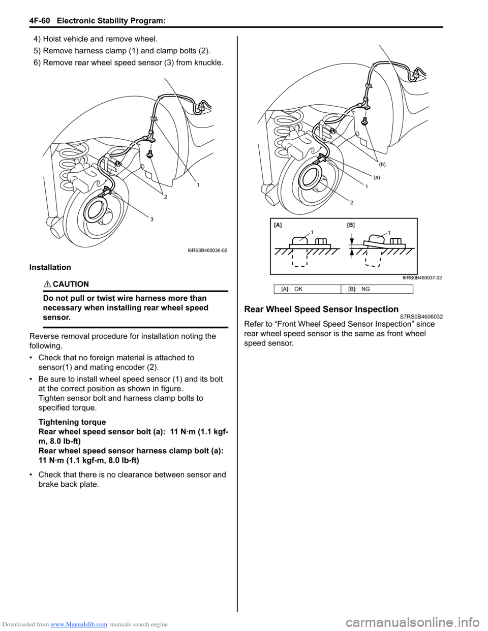
5) Remove harness clamp (1) and clamp bolts (2).
6) Remove rear wheel speed sensor (3) from knuckle.
Installation
CAUTION!
Do not pull or twist wi re harness more than
necessary when installing rear wheel speed
sensor.
Reverse removal procedure for installation noting the
following.
• Check that no foreign material is attached to sensor(1) and mating encoder (2).
• Be sure to install wheel speed sensor (1) and its bolt at the correct position as shown in figure.
Tighten sensor bolt and harness clamp bolts to
specified torque.
Tightening torque
Rear wheel speed sensor bolt (a): 11 N·m (1.1 kgf-
m, 8.0 lb-ft)
Rear wheel speed sensor harness clamp bolt (a):
11 N·m (1.1 kgf-m, 8.0 lb-ft)
• Check that there is no clearance between sensor and brake back plate.
Rear Wheel Speed Sensor InspectionS7RS0B4606032
Refer to “Front Wheel Speed Sensor Inspection” since
rear wheel speed sensor is the same as front wheel
speed sensor.
3
2
1
I6RS0B460036-02
[A]: OK [B]: NG
1
(b)
[A][B]
11
(a)
2
I6RS0B460037-02
Page 737 of 1496
Downloaded from www.Manualslib.com manuals search engine Automatic Transmission/Transaxle: 5A-93
Select Cable AdjustmentS7RS0B5106013
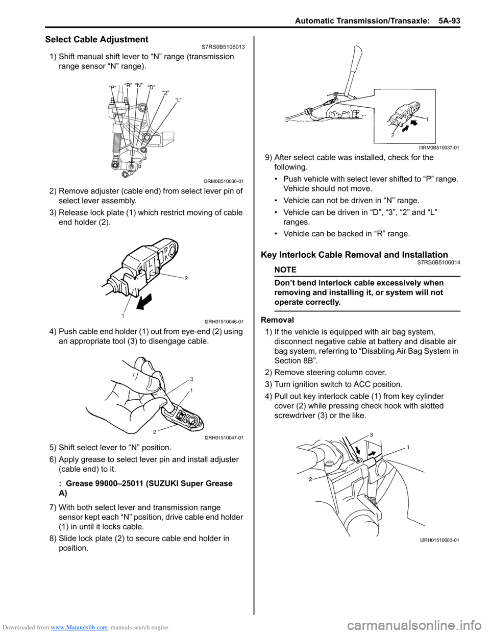
1) Shift manual shift lever to “N” range (transmission range sensor “N” range).
2) Remove adjuster (cable end) from select lever pin of select lever assembly.
3) Release lock plate (1) which restrict moving of cable end holder (2).
4) Push cable end holder (1) out from eye-end (2) using an appropriate tool (3) to disengage cable.
5) Shift select lever to “N” position.
6) Apply grease to select lever pin and install adjuster (cable end) to it.
: Grease 99000–25011 (SUZUKI Super Grease
A)
7) With both select lever and transmission range sensor kept each “N” position, drive cable end holder
(1) in until it locks cable.
8) Slide lock plate (2) to secure cable end holder in position. 9) After select cable was
installed, check for the
following.
• Push vehicle with select lever shifted to “P” range. Vehicle should not move.
• Vehicle can not be driven in “N” range.
• Vehicle can be driven in “D”, “3”, “2” and “L” ranges.
• Vehicle can be backed in “R” range.
Key Interlock Cable Removal and InstallationS7RS0B5106014
NOTE
Don’t bend interlock cable excessively when
removing and installing it, or system will not
operate correctly.
Removal
1) If the vehicle is equipped with air bag system, disconnect negative cable at battery and disable air
bag system, referring to “Disabling Air Bag System in
Section 8B”.
2) Remove steering column cover.
3) Turn ignition switch to ACC position.
4) Pull out key interlock cable (1) from key cylinder cover (2) while pressing check hook with slotted
screwdriver (3) or the like.
“P” “R”
“N”
“D”
“2”
“L”
I3RM0B510036-01
I2RH01510046-01
I2RH01510047-01
I3RM0B510037-01
1
2 3
I2RH01510083-01
Page 758 of 1496
Downloaded from www.Manualslib.com manuals search engine 5A-114 Automatic Transmission/Transaxle:
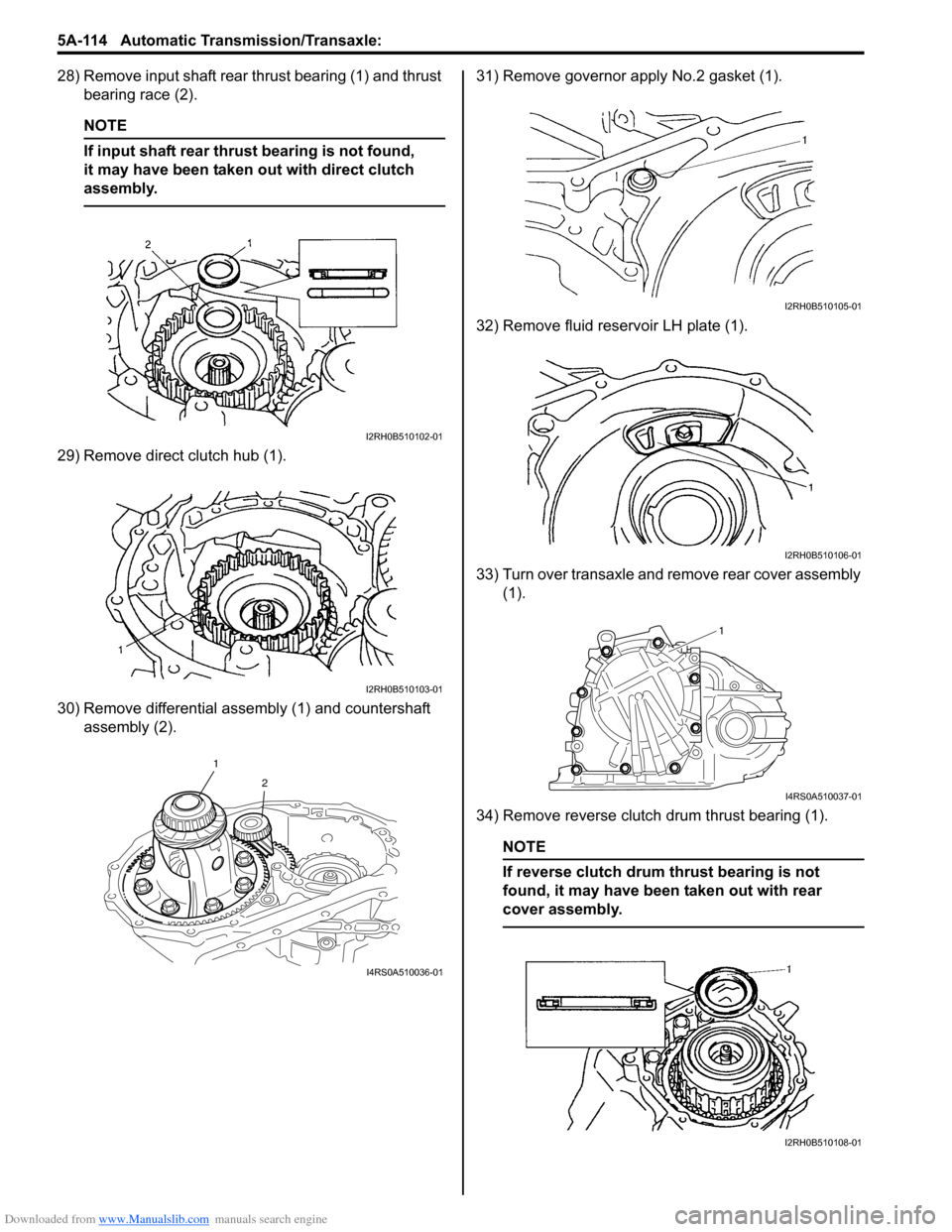
28) Remove input shaft rear thrust bearing (1) and thrust bearing race (2).
NOTE
If input shaft rear thrust bearing is not found,
it may have been taken out with direct clutch
assembly.
29) Remove direct clutch hub (1).
30) Remove differential assembly (1) and countershaft assembly (2). 31) Remove governor apply No.2 gasket (1).
32) Remove fluid reservoir LH plate (1).
33) Turn over transaxle and remove rear cover assembly
(1).
34) Remove reverse clutch drum thrust bearing (1).
NOTE
If reverse clutch drum thrust bearing is not
found, it may have been taken out with rear
cover assembly.
I2RH0B510102-01
I2RH0B510103-01
1 2
I4RS0A510036-01
I2RH0B510105-01
I2RH0B510106-01
1
I4RS0A510037-01
I2RH0B510108-01
Page 834 of 1496
Downloaded from www.Manualslib.com manuals search engine 5B-20 Manual Transmission/Transaxle:
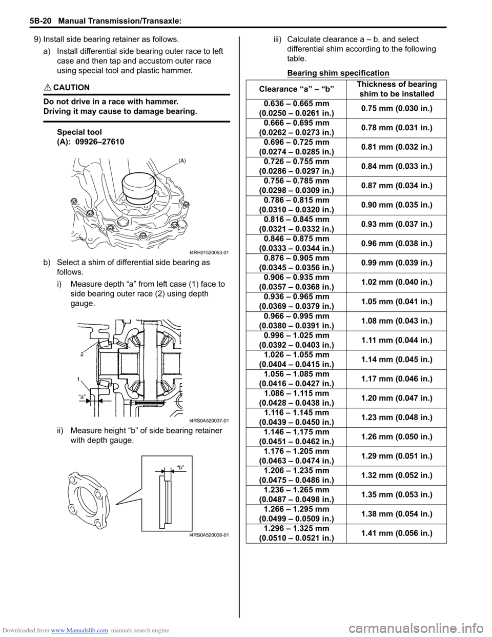
9) Install side bearing retainer as follows.a) Install differential side bearing outer race to left case and then tap and accustom outer race
using special tool and plastic hammer.
CAUTION!
Do not drive in a race with hammer.
Driving it may cause to damage bearing.
Special tool
(A): 09926–27610
b) Select a shim of differential side bearing as follows.
i) Measure depth “a” from left case (1) face to side bearing outer race (2) using depth
gauge.
ii) Measure height “b” of side bearing retainer with depth gauge. iii) Calculate clearance a – b, and select
differential shim acco rding to the following
table.
Bearing shim specification
(A)
I4RH01520053-01
I4RS0A520037-01
“b”
I4RS0A520038-01
Clearance “a” – “b” Thickness of bearing
shim to be installed
0.636 – 0.665 mm
(0.0250 – 0.0261 in.) 0.75 mm (0.030 in.)
0.666 – 0.695 mm
(0.0262 – 0.0273 in.) 0.78 mm (0.031 in.)
0.696 – 0.725 mm
(0.0274 – 0.0285 in.) 0.81 mm (0.032 in.)
0.726 – 0.755 mm
(0.0286 – 0.0297 in.) 0.84 mm (0.033 in.)
0.756 – 0.785 mm
(0.0298 – 0.0309 in.) 0.87 mm (0.034 in.)
0.786 – 0.815 mm
(0.0310 – 0.0320 in.) 0.90 mm (0.035 in.)
0.816 – 0.845 mm
(0.0321 – 0.0332 in.) 0.93 mm (0.037 in.)
0.846 – 0.875 mm
(0.0333 – 0.0344 in.) 0.96 mm (0.038 in.)
0.876 – 0.905 mm
(0.0345 – 0.0356 in.) 0.99 mm (0.039 in.)
0.906 – 0.935 mm
(0.0357 – 0.0368 in.) 1.02 mm (0.040 in.)
0.936 – 0.965 mm
(0.0369 – 0.0379 in.) 1.05 mm (0.041 in.)
0.966 – 0.995 mm
(0.0380 – 0.0391 in.) 1.08 mm (0.043 in.)
0.996 – 1.025 mm
(0.0392 – 0.0403 in.) 1.11 mm (0.044 in.)
1.026 – 1.055 mm
(0.0404 – 0.0415 in.) 1.14 mm (0.045 in.)
1.056 – 1.085 mm
(0.0416 – 0.0427 in.) 1.17 mm (0.046 in.)
1.086 – 1.115 mm
(0.0428 – 0.0438 in.) 1.20 mm (0.047 in.)
1.116 – 1.145 mm
(0.0439 – 0.0450 in.) 1.23 mm (0.048 in.)
1.146 – 1.175 mm
(0.0451 – 0.0462 in.) 1.26 mm (0.050 in.)
1.176 – 1.205 mm
(0.0463 – 0.0474 in.) 1.29 mm (0.051 in.)
1.206 – 1.235 mm
(0.0475 – 0.0486 in.) 1.32 mm (0.052 in.)
1.236 – 1.265 mm
(0.0487 – 0.0498 in.) 1.35 mm (0.053 in.)
1.266 – 1.295 mm
(0.0499 – 0.0509 in.) 1.38 mm (0.054 in.)
1.296 – 1.325 mm
(0.0510 – 0.0521 in.) 1.41 mm (0.056 in.)
Page 977 of 1496
Downloaded from www.Manualslib.com manuals search engine Air Conditioning System: Manual Type 7B-29
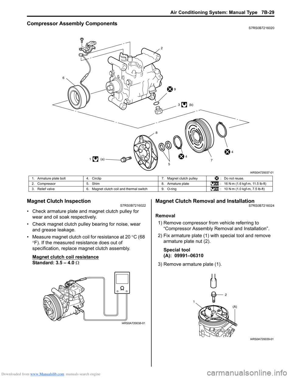
Compressor Assembly ComponentsS7RS0B7216020
Magnet Clutch InspectionS7RS0B7216022
• Check armature plate and magnet clutch pulley for wear and oil soak respectively.
• Check magnet clutch pulley bearing for noise, wear and grease leakage.
• Measure magnet clutch coil for resistance at 20 °C (68
° F). If the measured resistance does out of
specification, replace magnet clutch assembly.
Magnet clutch coil resistance
Standard: 3.5 – 4.0 Ω
Magnet Clutch Removal and InstallationS7RS0B7216024
Removal
1) Remove compressor from vehicle referring to “Compressor Assembly Re moval and Installation”.
2) Fix armature plate (1) with special tool and remove armature plate nut (2).
Special tool
(A): 09991–06310
3) Remove armature plate (1).
6
2
9
44
3 (b)
1 (a) 7
5
8
I4RS0A720037-01
1. Armature plate bolt
4. Circlip 7. Magnet clutch pulley: Do not reuse.
2. Compressor 5. Shim 8. Armature plate: 16 N⋅m (1.6 kgf-m, 11.5 lb-ft)
3. Relief valve 6. Magnet clutch coil and thermal switch 9. O-ring : 10 N⋅m (1.0 kgf-m, 7.5 lb-ft)
I4RS0A720038-01
2
1 (A)
I4RS0A720039-01