2006 SUZUKI SWIFT gas type
[x] Cancel search: gas typePage 10 of 1496
Downloaded from www.Manualslib.com manuals search engine 00-5 Precautions:
• When performing service to electrical parts that does not require use of battery power, disconnect the
negative cable of the battery.
• When disconnecting the negative cable from the battery, be careful to the following.
– Check and record DTCs in ECM and HVAC control module if necessary before disconnecting.
– Record displayed contents of the clock and/or audio system, etc. before disconnecting and reset it
as before after connecting.
– For vehicle equipped with electric throttle body system, perform electric throttle body system
calibration referring to “Electric Throttle Body
System Calibration in Section 1C” after
reconnecting the negative cable to the battery.
– For vehicle equipped with ESP ®, calibrate steering
angle sensor referring to “Sensor Calibration in
Section 4F” after reconnecting the negative cable
to the battery.
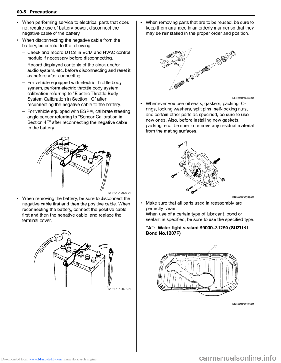
• When removing the battery, be sure to disconnect the negative cable first and then the positive cable. When
reconnecting the battery, connect the positive cable
first and then the negative cable, and replace the
terminal cover. • When removing parts that are to be reused, be sure to
keep them arranged in an orderly manner so that they
may be reinstalled in the proper order and position.
• Whenever you use oil seals, gaskets, packing, O- rings, locking washers, split pins, self-locking nuts,
and certain other parts as specified, be sure to use
new ones. Also, before installing new gaskets,
packing, etc., be sure to remove any residual material
from the mating surfaces.
• Make sure that all parts used in reassembly are perfectly clean.
When use of a certain type of lubricant, bond or
sealant is specified, be sure to use the specified type.
“A”: Water tight sealant 99000–31250 (SUZUKI
Bond No.1207F)
I2RH01010026-01
I2RH01010027-01
I2RH01010028-01
I2RH01010029-01
I2RH01010030-01
Page 286 of 1496
Downloaded from www.Manualslib.com manuals search engine 1D-1 Engine Mechanical:
Engine
Engine Mechanical
General Description
Engine Construction DescriptionS7RS0B1401001
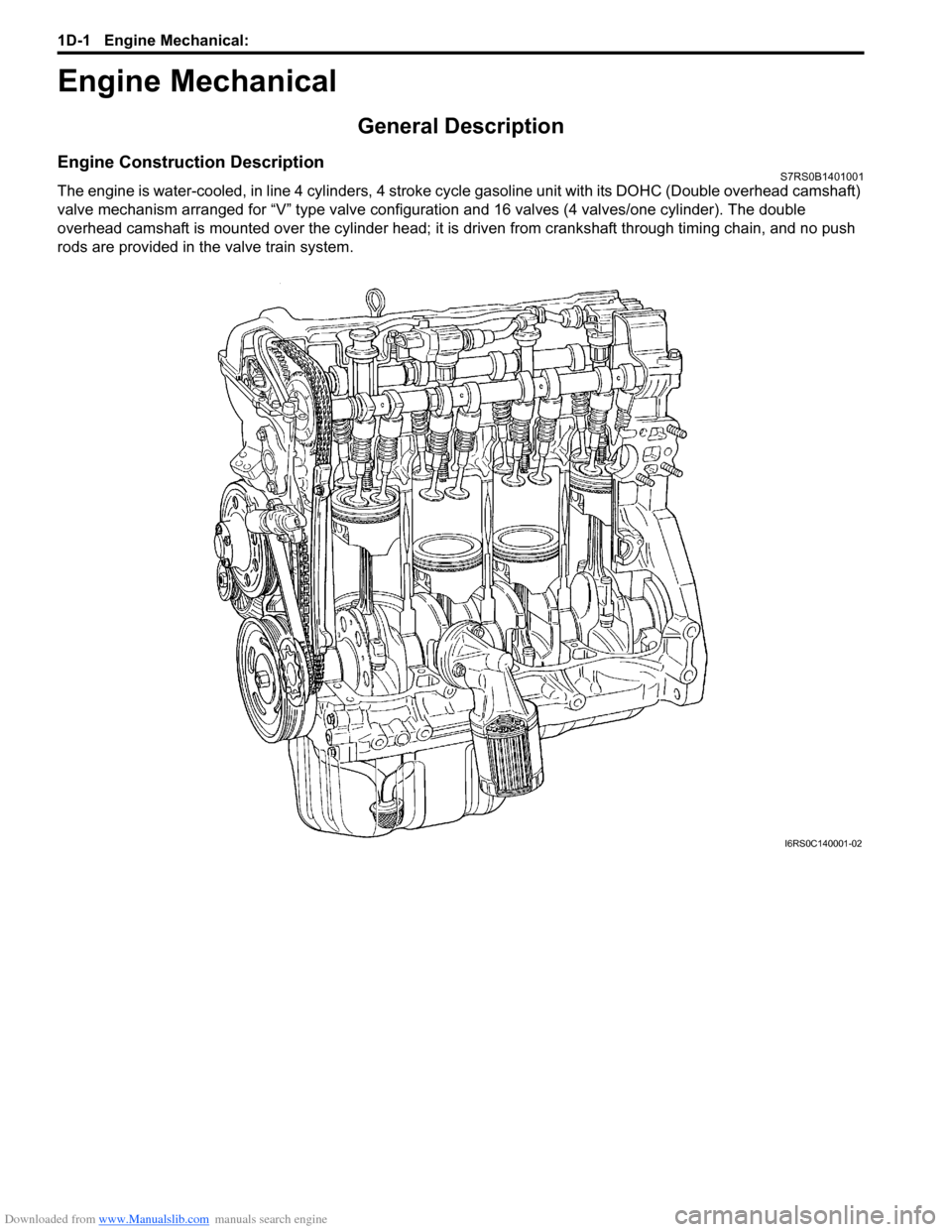
The engine is water-cooled, in line 4 cylinders, 4 stroke cycle gasoline unit with its DOHC (Double overhead camshaft)
valve mechanism arranged for “V” type valve configurat ion and 16 valves (4 valves/one cylinder). The double
overhead camshaft is mounted over the cy linder head; it is driven from crankshaft through timing chain, and no push
rods are provided in the valve train system.
I6RS0C140001-02
Page 376 of 1496
Downloaded from www.Manualslib.com manuals search engine 1G-1 Fuel System:
Engine
Fuel System
Precautions
Precautions on Fuel System ServiceS7RS0B1700001
WARNING!
Before attempting service of any type on fuel system, the following should be always observed in
order to reduce the risk of fire and personal injury.
• Disconnect negative cable at battery.
• Do not smoke, and place no smoking signs near work area.
• Be sure to have CO
2 fire extinguisher handy.
• Be sure to perform work in a well-ventilated area and away from any open flames (such as gas hot heater).
• Wear safety glasses.
• To relieve fuel vapor pressure in fuel tank, remove fuel filler cap from fuel filler neck and then
reinstall it.
• As fuel feed line is still under high fuel pr essure even after stopping engine, loosening or
disconnecting fuel feed line directly may cause dangerous spout of fuel. Before loosening or
disconnecting fuel feed line, make sure to relieve fuel pressure referring to “Fuel Pressure Relief
Procedure”.
• A small amount of fuel may be released when the fuel line is disconnected. In order to reduce the risk of personal injury, cover a shop cloth to the fitting to be disconnected. Be sure to put that cloth
in an approved container after disconnecting.
• Never run engine with fuel pump relay disconnected when engine and exhaust system are hot.
• Note that fuel hose connection varies with each type of pipe. Be sure to connect and clamp each hose correctly referring to “Fuel Hose Disconnecting and Reconnecting”.
After connecting, make sure that it has no twist or kink.
• When installing inje ctor or fuel feed pipe, lubr icate its O-ring with gasoline.
General Description
Fuel System DescriptionS7RS0B1701001
CAUTION!
This engine requires the unleaded fuel only.
The leaded and/or low lead fuel can result in
engine damage and reduce the effectiveness
of the emission control system.
The main components of the fuel system are fuel tank,
fuel pump assembly (with fuel filter, fuel level gauge, fuel
pressure regulator, fuel feed line and fuel vapor line.
For the details of fuel flow, refer to “Fuel Delivery System
Diagram”.
Fuel Delivery System DescriptionS7RS0B1701002
The fuel delivery system consists of the fuel tank, fuel
pump assembly (with built-in f uel filter and fuel pressure
regulator), delivery pipe, injectors and fuel feed line.
The fuel in the fuel tank is pumped up by the fuel pump,
sent into delivery pipe and injected by the injectors.
As the fuel pump assembly is equipped with built-in fuel
filter and fuel pressure regulator, the fuel is filtered and
its pressure is regulated before being sent to the feed
pipe.
The excess fuel at fuel pressure regulation process is
returned back into the fuel tank.
Also, fuel vapor generated in fuel tank is led through the
fuel vapor line into the EVAP canister.
For system diagram, refer to “Fuel Delivery System
Diagram”.
Page 398 of 1496

Downloaded from www.Manualslib.com manuals search engine 1H-6 Ignition System:
Ignition Spark TestS7RS0B1804004
1) Remove air cleaner assembly with air intake pipe.
2) Disconnect all injector couplers from injectors.
WARNING!
Without disconnection of injector couplers,
combustible gas may come out from spark
plug holes during this test and may get
ignited in engine room.
3) Remove spark plug and check it for condition and
type referring to “Spark Plug Inspection”.
4) If OK, connect ignition coil coupler to ignition coil assembly and connect spark plug to ignition coil
assembly or high-tension cord. Ground spark plug. 5) Crank engine and check if each spark plug sparks.
6) If no spark is emitted, inspect the related parts as
described in “Ignition System Symptom Diagnosis”.
Repair Instructions
High-Tension Cord Removal and InstallationS7RS0B1806001
Removal
1) Remove air cleaner assembly with air intake pipe and cylinder head upper cover.
2) Disconnect No.1 cylinder (2) and No.3 cylinder (3)
high-tension cords from ignition coil assemblies (1)
while gripping each cap.
3) Pull out high-tension cords from spark plugs while gripping each cap.
CAUTION!
• Removal of high-tension cords together with clamps will be recommended so as
not to damage their inside wire (resistive
conductor).
• For the same reason, pull out each connection by gripping cap portion.
Installation
1) Install No.1 cylinder (2) and No.3 cylinder (3) high-
tension cords to spark plugs and ignition coil
assemblies (1) while gripping each cap.
CAUTION!
• Never attempt to use metal conductor high-tension cords as replacing parts.
• Insert each cap portion fully when installing high-tension cords.
I4RS0A180006-01
I4RS0A180003-01
I4RS0A180004-01
Page 486 of 1496
Downloaded from www.Manualslib.com manuals search engine 3A-8 Drive Shaft / Axle:
Reassembly
Tripod joint
Judging from abnormality noted before disassembly and
what is found through visual check of component parts
after disassembly, prepare replacing parts and proceed
to reassembly.
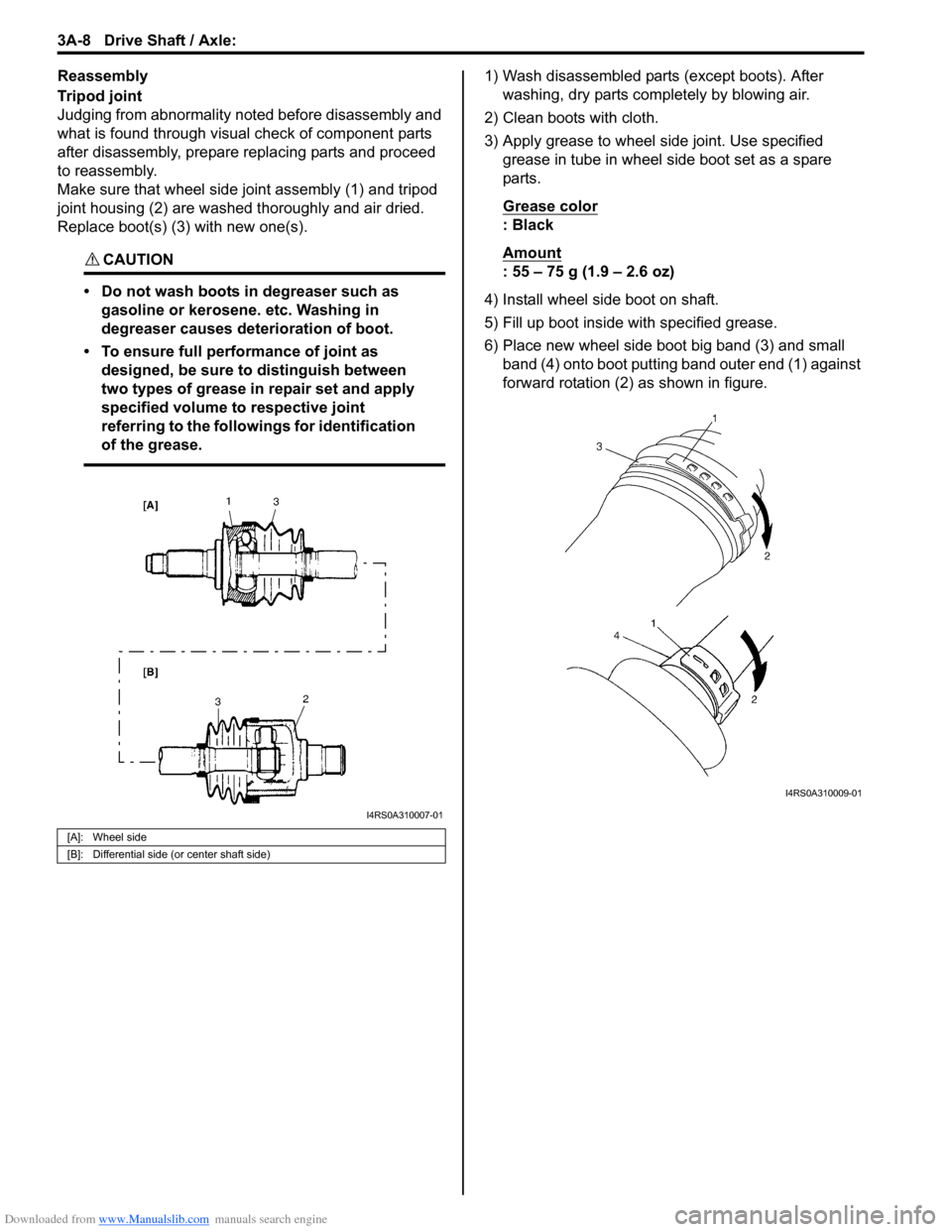
Make sure that wheel side joint assembly (1) and tripod
joint housing (2) are washed thoroughly and air dried.
Replace boot(s) (3) with new one(s).
CAUTION!
• Do not wash boots in degreaser such as gasoline or kerosene. etc. Washing in
degreaser causes deterioration of boot.
• To ensure full performance of joint as designed, be sure to distinguish between
two types of grease in repair set and apply
specified volume to respective joint
referring to the followings for identification
of the grease.
1) Wash disassembled parts (except boots). After washing, dry parts comp letely by blowing air.
2) Clean boots with cloth.
3) Apply grease to wheel side joint. Use specified grease in tube in wheel side boot set as a spare
parts.
Grease color
: Black
Amount
: 55 – 75 g (1.9 – 2.6 oz)
4) Install wheel side boot on shaft.
5) Fill up boot inside with specified grease.
6) Place new wheel side boot big band (3) and small band (4) onto boot putting band outer end (1) against
forward rotation (2) as shown in figure.
[A]: Wheel side
[B]: Differential side (or center shaft side)
I4RS0A310007-01
I4RS0A310009-01
Page 489 of 1496
Downloaded from www.Manualslib.com manuals search engine Drive Shaft / Axle: 3A-11
DOJ
Judging from abnormality noted before disassembly and
what is found through visual check of components parts
after disassembly, prepare replacing parts and proceed
to reassembly.
Make sure that wheel side joint assembly and DOJ
housing are washed thoroughly and air dried.
Replace boot(s) with new one(s).
CAUTION!
• Do not wash boots in degreaser such as gasoline or kerosene. etc. Washing in
degreaser causes deterioration of boot.
• To ensure full performance of joint as designed, be sure to distinguish between
two types of grease in repair set and apply
specified volume to respective joint
referring to the followings for identification
of the grease.
1) Wash disassembled parts (except boots). After washing, dry parts completely by blowing air.
2) Clean boots with cloth.
3) Apply grease to wheel side joint. Use specified
grease in tube in wheel side boot set as a spare
parts.
Grease color
: Black
Amount
: 55 – 75 g (1.9 – 2.6 oz)
4) Install wheel side boot on shaft.
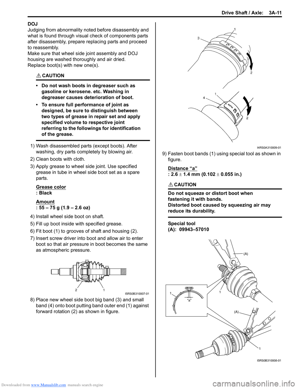
5) Fill up boot inside wi th specified grease.
6) Fit boot (1) to grooves of shaft and housing (2).
7) Insert screw driver into boot and allow air to enter boot so that air pressure in boot becomes the same
as atmospheric pressure.
8) Place new wheel side boot big band (3) and small band (4) onto boot putting band outer end (1) against
forward rotation (2) as shown in figure. 9) Fasten boot bands (1) using special tool as shown in
figure.
Distance “a”
: 2.6 ± 1.4 mm (0.102 ± 0.055 in.)
CAUTION!
Do not squeeze or distort boot when
fastening it with bands.
Distorted boot caused by squeezing air may
reduce its durability.
Special tool
(A): 09943–57010
21I5RS0B310007-01
I4RS0A310009-01
(A)
1
(A)
1
“a”
1
I5RS0B310008-01
Page 969 of 1496
Downloaded from www.Manualslib.com manuals search engine Air Conditioning System: Manual Type 7B-21
Removal of Manifold Gauge Set
WARNING!
High pressure side is under high pressure.
Therefore, be careful not to get injured
especially on your eyes and skin.
For the A/C system charged with the specified amount of
refrigerant, remove manifold gauge set as follows:
1) Close low pressure side valve of manifold gauge set. (The high pressure side valve is closed continuously
during the process of charging.)
2) Close refrigerant container valve.
3) Stop engine.
4) Using shop rag, remove charging hoses from service valves. This operation must be performed quickly.
5) Put caps on service valves.
Check A/C System for Refrigerant Leaks
Whenever a refrigerant leak is suspected in the system
or any service operation has been performed which may
result in malfunction of lines and connections, it is
advisable to check for leaks.
Common sense should be used during refrigerant leak
test, since the need and extent of any such test will, in
general, depend upon the nature of a complaint and the
type of a service performed on the system.
Liquid leak detector
WARNING!
• To prevent explosions and fires, make sure that there are no flammables in the vicinity.
• When the refrigerant exposed to fire, it turns into a poisonous gas (phosgene). Do
not inhale this gas.
There is a number of fittings and places throughout the
A/C system where a liquid leak detector solution may be
used to pinpoint refrigerant leaks.
By merely applying the solution to the area in question
with a swab, such as attached to the cap of a vial,
bubbles will form within seconds if there is a leak.
For confined areas, such as sections of the evaporator
and condenser, an electronic (refrigerant) leak detector
is more practical fo r determining leaks.
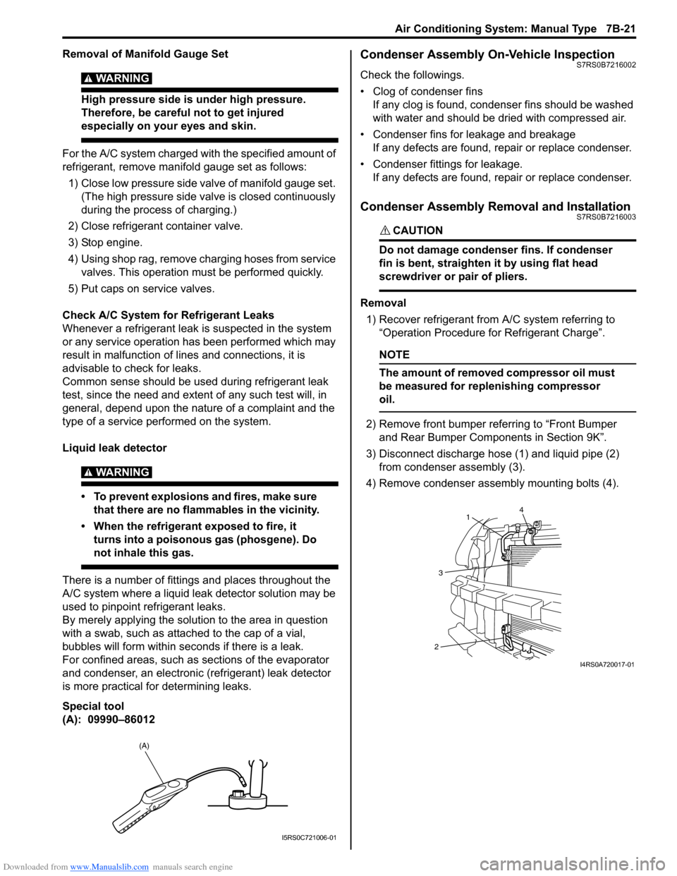
Special tool
(A): 09990–86012
Condenser Assembly On-Vehicle InspectionS7RS0B7216002
Check the followings.
• Clog of condenser fins If any clog is found, cond enser fins should be washed
with water and should be dried with compressed air.
• Condenser fins for leakage and breakage If any defects are found, repair or replace condenser.
• Condenser fittings for leakage. If any defects are found, repair or replace condenser.
Condenser Assembly Removal and InstallationS7RS0B7216003
CAUTION!
Do not damage condenser fins. If condenser
fin is bent, straighten it by using flat head
screwdriver or pair of pliers.
Removal
1) Recover refrigerant from A/C system referring to “Operation Procedure for Refrigerant Charge”.
NOTE
The amount of removed compressor oil must
be measured for replenishing compressor
oil.
2) Remove front bumper referring to “Front Bumper and Rear Bumper Components in Section 9K”.
3) Disconnect discharge hose (1) and liquid pipe (2) from condenser assembly (3).
4) Remove condenser assembly mounting bolts (4).
(A)
I5RS0C721006-01
4
1
3
2
I4RS0A720017-01
Page 981 of 1496

Downloaded from www.Manualslib.com manuals search engine Air Conditioning System: Manual Type 7B-33
Special Tools and Equipment
Recommended Service MaterialS7RS0B7218001
NOTE
Required service material is also described in the following.
“Precautions on Servicing A/C System”
Special ToolS7RS0B7218002
Material SUZUKI recommended product or Specification Note
Compressor oil MATSUSHITADEN KI GU10 P/No.: 99000–99015–
00A �)
/ �)
Silicon sealant SUZUKI SILICON SEALANT KE-
347W (100g) P/No.: 99000–34220
�)
09900–06107 09990–86012
Snap ring pliers (opening
type) Gas leak detector
�) / �) / �) / �) This kit includes following
items. 1. Gas leak detector,
2. Instruction manual, 3.
Filter, 4. Sensor, 5. Dri-sell
battery (size D)�) / �)
09991–06310
Armature plate holder
�) / �)
1 2
3 4
5