2006 SUBARU IMPREZA weight
[x] Cancel search: weightPage 74 of 365

Seat, seatbelt and SRS airbags 1-47
CONTINUED
Operation
A) Drivers side
B) Passenger s side
1) SRS AIRBAGs deploy as soon as a collision occurs.
2) After deployment, SRS AIRBAGs start to deflate im mediately so that the drivers vision is not
obstructed.
A B
1
2
100619
The SRS airbag can function only when
the ignition switch is in the ON position.
The Subaru advanced frontal airbag sys-
tem is designed to determine the activa-
tion or deactivation condition of the front
passenger s SRS frontal airbag depend-
ing on the total load on the front passen-
ger s seat monitored by the front passen-
ger s occupant detection system weight
sensor. For this reason, only the driver s
SRS frontal airbag may deploy in the
event of a collision, but this does not mean
failure of the system.
If the front sub sensors inside both front
fenders and the impact sensors in the air-
bag control module detect a predeter-
mined amount of force during a frontal col-
lision, the control module sends signals to
the airbag module(s) (only driver s module
or both driver s and front passenger s
modules) instructing the module(s) to in-
flate the SRS frontal airbag(s). The driv-
er s and front passenger s SRS frontal air-
bags use dual stage inflators. The two in-
flators of each airbag are triggered either
sequentially or simultaneously, depending
on the severity of impact, backward-for-
ward adjustment of the driver s seat posi-
tion and fastening/unfastening of the seat-
belt in the case of the driver s SRS frontal
airbag and depending on the severity of
impact and the total load on the seat in the
Page 84 of 365
Seat, seatbelt and SRS airbags 1-57
CONTINUED
Side airbag sensor (Center pillar right
hand side)
Side airbag sensor (Center pillar left
hand side)
Side airbag module (Driver s side)
Side airbag module (Front passenger s
side)
Seatbelt pretensioner (Driver s side)
Seatbelt pretensioner (Front passen-
ger s side)
Seatbelt buckle switch (Driver s side)
Seatbelt buckle switch (Front passen-
ger s side)
Driver s seat position sensor
Front passenger s seatbelt tension sen-
sor
Front passenger s occupant detection
system weight sensor
Front passenger s occupant detection
control module
Front passenger s frontal airbag ON
and OFF indicator
All related wiring
SRS airbag system servicing
If the warning light exhibits any of
the following conditions, there may
be a malfunction in the seatbelt pre-
tensioners and/or SRS airbag sys-
tem. Immediately take your vehicle
to your nearest SUBARU dealer to
have the system checked. Unless
checked and properly repaired, the
seatbelt pretensioners and/or SRS
airbag will not operate properly in
the event of a collision, which may
increase the risk of injury.
Flashing or flickering of the warn-
ing light
No illumination of the warning
light when the ignition switch is
first turned to the ON position
Continuous illumination of the
warning light
Illumination of the warning light
while driving
When discarding an airbag mod-
ule or scrapping the entire vehicle
damaged by a collision, consult
your SUBARU dealer.
The SRS airbag has no user-ser-
viceable parts. Do not use electri-
cal test equipment on any circuit
related to the SRS airbag system.
For required servicing of the SRS
airbag, see your nearest SUBARU
dealer. Tampering with or discon-
necting the system s wiring could
result in accidental inflation of the
SRS airbag or could make the sys-
tem inoperative, which may result
in serious injury. The wiring har-
nesses of the SRS airbag system
are covered with yellow insulation
and system connectors are yellow
for easy identification.
Page 195 of 365
6-10 Interior equipment
Cargo area cover (Wagon if
equipped)
The cargo area cover is provided for cov-
ering the cargo area and to protect its con-
tents from direct sunlight. This cover is de-
tachable to make room for additional car-
go.
Using the cover
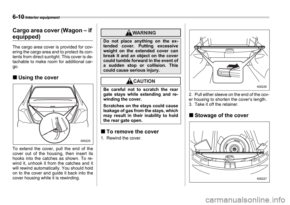
To extend the cover, pull the end of the
cover out of the housing, then insert its
hooks into the catches as shown. To re-
wind it, unhook it from the catches and it
will rewind automatically. You should hold
on to the cover and guide it back into the
cover housing while it is rewinding.
To remove the cover
1. Rewind the cover. 2. Pull either sleeve on the end of the cov-
er housing to shorten the cover
s length.
3. Take it off the retainer.
Stowage of the cover
600225
Do not place anything on the ex-
tended cover. Putting excessive
weight on the extended cover can
break it and an object on the cover
could tumble forward in the event of
a sudden stop or collision. This
could cause serious injury.
Be careful not to scratch the rear
gate stays while extending and re-
winding the cover.
Scratches on the stays could cause
leakage of gas from the stays, which
may result in their inability to hold
the rear gate open.
600226
600227
Page 197 of 365
6-12 Interior equipment
Cargo area bars
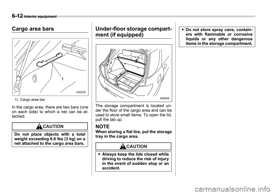
1) Cargo area bar
In the cargo area, there are two bars (one
on each side) to which a net can be at-
tached.
Under-floor storage compart-
ment (if equipped)
The storage compartment is located un-
der the floor of the cargo area and can be
used to store small items. To open the lid,
pull the tab up.
NOTE
When storing a flat tire, put the storage
tray in the cargo area.Do not place objects with a total
weight exceeding 6.6 lbs (3 kg) on a
net attached to the cargo area bars.
1
600528
Always keep the lids closed while
driving to reduce the risk of injury
in the event of sudden stop or an
accident.
600539
Do not store spray cans, contain-
ers with flammable or corrosive
liquids or any other dangerous
items in the storage compartment.
Page 228 of 365

8
Driving tips
New vehicle break-in driving the first 1,000
miles (1,600 km) .................................. ............ 8-2
Fuel economy hints ................................ ........... 8-2
Engine exhaust gas (Carbon monoxide) ......... 8-2
Catalytic converter ............................... .............. 8-3
Periodic inspections .............................. ............ 8-4
Driving in foreign countries ...................... ........ 8-4
Driving tips for AWD vehicles ..................... ...... 8-5
Off road driving .................................. ................ 8-6
All AWD models except OUTBACK SPORT and vehicles with 17 inch tires ....................... ............ 8-6
OUTBACK SPORT ..................................... ............. 8-6
Winter driving .................................... ................. 8-8
Operation during cold weather ..................... ......... 8-8
Driving on snowy and icy roads .................... ........ 8-9
Corrosion protection .............................. ................ 8-10
Snow tires ........................................ ....................... 8-10
Tire chains ....................................... ........................ 8-11
Rocking the vehicle ............................... ................. 8-12
Loading your vehicle .............................. ........... 8-12
Vehicle capacity weight ........................... .............. 8-13
GVWR and GAWR (Gross Vehicle Weight Rating and Gross Axle Weight Rating) ..................... ...... 8-14
Roof rail and crossbar (if equipped) .............. ....... 8-14
Trailer hitch (if equipped) ....................... ........... 8-17
Connecting a trailer .............................. .................. 8-17
When you do not tow a trailer ..................... .......... 8-19Trailer towing ....................................
.................. 8-19
Warranties and maintenance ........................ ......... 8-19
Maximum load limits ............................... ............... 8-20
Trailer hitches ................................... ...................... 8-23
Connecting a trailer .............................. .................. 8-24
Trailer towing tips ............................... .................... 8-25
Page 240 of 365
Driving tips 8-13
CONTINUED
NOTE
For better fuel economy, do not carry
unneeded cargo.
Vehicle capacity weight
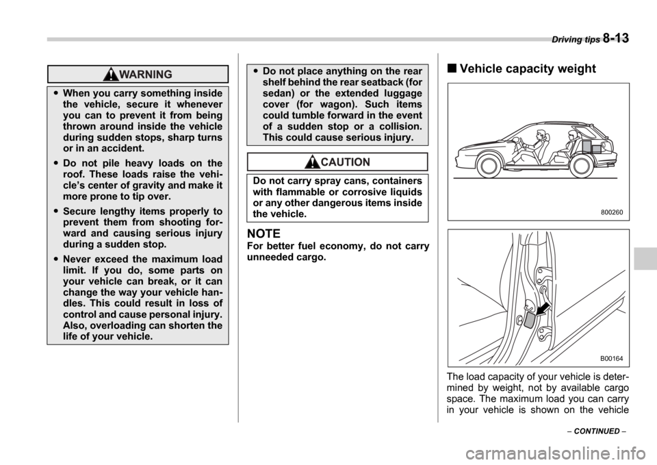
The load capacity of your vehicle is deter-
mined by weight, not by available cargo
space. The maximum load you can carry
in your vehicle is shown on the vehicle
When you carry something inside
the vehicle, secure it whenever
you can to prevent it from being
thrown around inside the vehicle
during sudden stops, sharp turns
or in an accident.
Do not pile heavy loads on the
roof. These loads raise the vehi-
cles center of gravity and make it
more prone to tip over.
Secure lengthy items properly to
prevent them from shooting for-
ward and causing serious injury
during a sudden stop.
Never exceed the maximum load
limit. If you do, some parts on
your vehicle can break, or it can
change the way your vehicle han-
dles. This could result in loss of
control and cause personal injury.
Also, overloading can shorten the
life of your vehicle.
Do not place anything on the rear
shelf behind the rear seatback (for
sedan) or the extended luggage
cover (for wagon). Such items
could tumble forward in the event
of a sudden stop or a collision.
This could cause serious injury.
Do not carry spray cans, containers
with flammable or corrosive liquids
or any other dangerous items inside
the vehicle.
800260
B00164
Page 241 of 365
8-14 Driving tips
placard attached to the driver s side door
pillar. It includes the total weight of the
driver and all passengers and their be-
longings, any optional equipment such as
a trailer hitch, roof rack or bike carrier,
etc., and the tongue load of a trailer.
GVWR and GAWR (Gross Ve-
hicle Weight Rating and
Gross Axle Weight Rating)
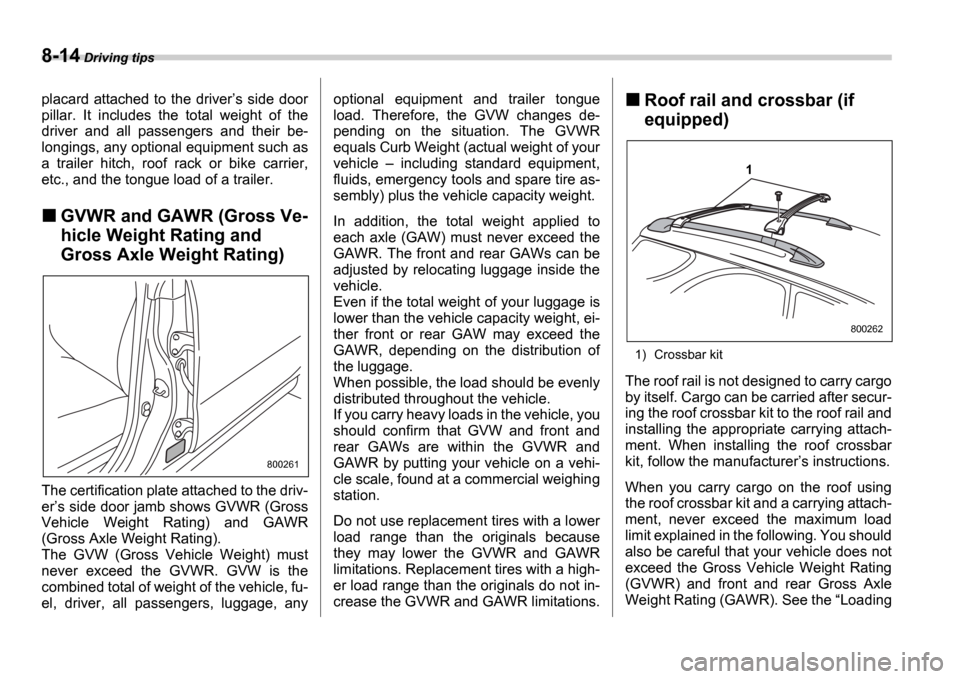
The certification plate attached to the driv-
er s side door jamb shows GVWR (Gross
Vehicle Weight Rating) and GAWR
(Gross Axle Weight Rating).
The GVW (Gross Vehicle Weight) must
never exceed the GVWR. GVW is the
combined total of weight of the vehicle, fu-
el, driver, all passengers, luggage, any optional equipment and trailer tongue
load. Therefore, the GVW changes de-
pending on the situation. The GVWR
equals Curb Weight (actual weight of your
vehicle
including standard equipment,
fluids, emergency tools and spare tire as-
sembly) plus the vehicle capacity weight.
In addition, the total weight applied to
each axle (GAW) must never exceed the
GAWR. The front and rear GAWs can be
adjusted by relocating luggage inside the
vehicle.
Even if the total weight of your luggage is
lower than the vehicle capacity weight, ei-
ther front or rear GAW may exceed the
GAWR, depending on the distribution of
the luggage.
When possible, the load should be evenly
distributed throughout the vehicle.
If you carry heavy loads in the vehicle, you
should confirm that GVW and front and
rear GAWs are within the GVWR and
GAWR by putting your vehicle on a vehi-
cle scale, found at a commercial weighing
station.
Do not use replacement tires with a lower
load range than the originals because
they may lower the GVWR and GAWR
limitations. Replacement tires with a high-
er load range than the originals do not in-
crease the GVWR and GAWR limitations.
Roof rail and crossbar (if
equipped)
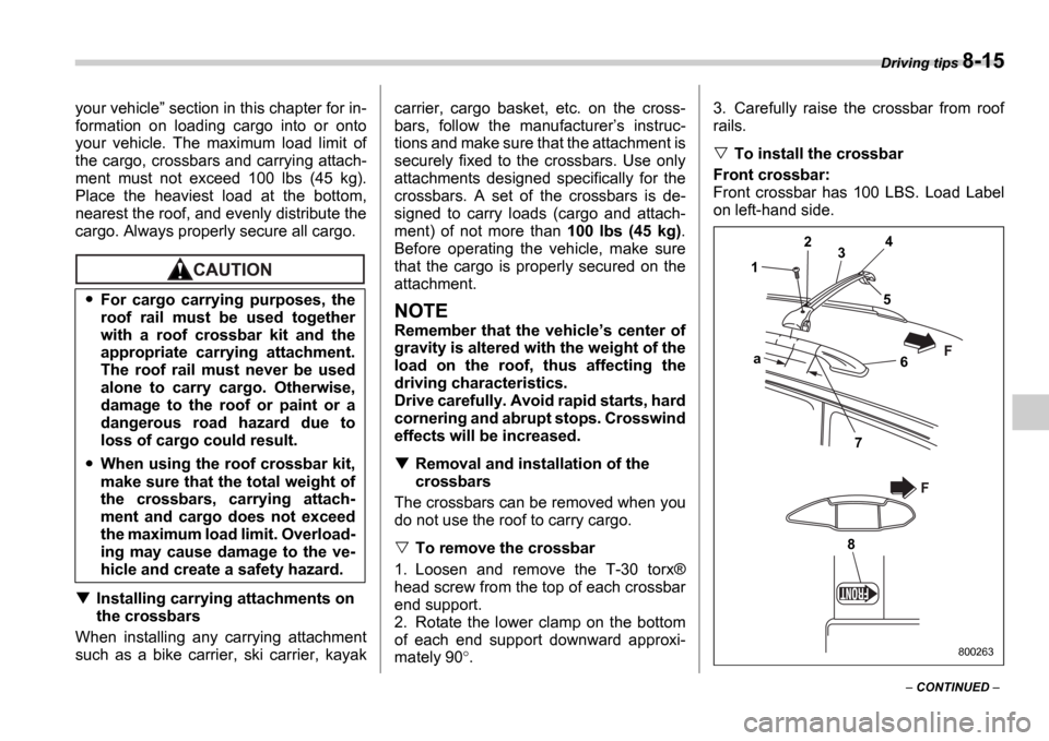
1) Crossbar kit
The roof rail is not designed to carry cargo
by itself. Cargo can be carried after secur-
ing the roof crossbar kit to the roof rail and
installing the appropriate carrying attach-
ment. When installing the roof crossbar
kit, follow the manufacturer s instructions.
When you carry cargo on the roof using
the roof crossbar kit and a carrying attach-
ment, never exceed the maximum load
limit explained in the following. You should
also be careful that your vehicle does not
exceed the Gross Vehicle Weight Rating
(GVWR) and front and rear Gross Axle
Weight Rating (GAWR). See the Loading
800261
1
800262
Page 242 of 365
Driving tips 8-15
CONTINUED
your vehicle
section in this chapter for in-
formation on loading cargo into or onto
your vehicle. The maximum load limit of
the cargo, crossbars and carrying attach-
ment must not exceed 100 lbs (45 kg).
Place the heaviest load at the bottom,
nearest the roof, and evenly distribute the
cargo. Always properly secure all cargo.
Installing carrying attachments on
the crossbars
When installing any carrying attachment
such as a bike carrier, ski carrier, kayak carrier, cargo basket, etc. on the cross-
bars, follow the manufacturer
s instruc-
tions and make sure that the attachment is
securely fixed to the crossbars. Use only
attachments designed specifically for the
crossbars. A set of the crossbars is de-
signed to carry loads (cargo and attach-
ment) of not more than 100 lbs (45 kg).
Before operating the vehicle, make sure
that the cargo is properly secured on the
attachment.
NOTE
Remember that the vehicle s center of
gravity is altered with the weight of the
load on the roof, thus affecting the
driving characteristics.
Drive carefully. Avoid rapid starts, hard
cornering and abrupt stops. Crosswind
effects will be increased.
Removal and installation of the
crossbars
The crossbars can be removed when you
do not use the roof to carry cargo.
To remove the crossbar
1. Loosen and remove the T-30 torx Æ
head screw from the top of each crossbar
end support.
2. Rotate the lower clamp on the bottom
of each end support downward approxi-
mately 90 . 3. Carefully raise the crossbar from roof
rails.
To install the crossbar
Front crossbar:
Front crossbar has 100 LBS. Load Label
on left-hand side.
For cargo carrying purposes, the
roof rail must be used together
with a roof crossbar kit and the
appropriate carrying attachment.
The roof rail must never be used
alone to carry cargo. Otherwise,
damage to the roof or paint or a
dangerous road hazard due to
loss of cargo could result.
When using the roof crossbar kit,
make sure that the total weight of
the crossbars, carrying attach-
ment and cargo does not exceed
the maximum load limit. Overload-
ing may cause damage to the ve-
hicle and create a safety hazard.
1 2
3 4
5
6
7
a
8
F
F
800263