2006 SUBARU IMPREZA engine
[x] Cancel search: enginePage 89 of 365
2-2 Keys and doors
Keys and doorsKeys
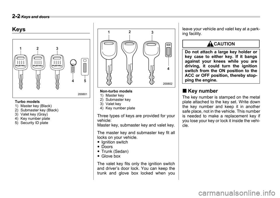
Turbo models
1) Master key (Black)
2) Submaster key (Black)
3) Valet key (Gray)
4) Key number plate
5) Security ID plate Non-turbo models
1) Master key
2) Submaster key
3) Valet key
4) Key number plate
Three types of keys are provided for your
vehicle:
Master key, submaster key and valet key.
The master key and submaster key fit all
locks on your vehicle.
Ignition switch
Doors
Trunk (Sedan)
Glove box
The valet key fits only the ignition switch
and driver s door lock. You can keep the
trunk and glove box locked when you leave your vehicle and valet key at a park-
ing facility.
Key number
The key number is stamped on the metal
plate attached to the key set. Write down
the key number and keep it in another
safe place, not in the vehicle. This number
is needed to make a replacement key if
you lose your key or lock it inside the vehi-
cle.
1 2 3
4 5
200801
12
3
4
200802
Do not attach a large key holder or
key case to either key. If it bangs
against your knees while you are
driving, it could turn the ignition
switch from the ON position to the
ACC or OFF position, thereby stop-
ping the engine.
Page 90 of 365
Keys and doors 2-3
CONTINUED
Immobilizer (Turbo models)
The immobilizer system is designed to
prevent an unauthorized person from
starting the engine. Only keys registered
with your vehicle s immobilizer system
can be used to operate your vehicle. Even
if an unregistered key fits into the ignition
switch and can be turned to the START
position, the engine will automatically stop
after several seconds.
Each immobilizer key contains a tran-
sponder in which the key s ID code is
stored. When a key is inserted into the ig-
nition switch and turned to the ON posi-
tion, the transponder transmits the key s
ID code to the immobilizer system s re-
ceiver. If the transmitted ID code matches
the ID code registered in the immobilizer
system, the system allows the engine to
be started. Since the ID code is transmit-
ted and acted upon almost instantly, the
immobilizer system does not impede nor-
mal starting of the engine.
If the engine fails to start, pull out the key
once before trying again. (Refer to the Ig-
nition switch section [chapter 3].)
This device complies with Part 15 of
the FCC Rules and with RSS-210 of In-
dustry Canada. Operation is subject to
the following two conditions: (1) This device may not cause harmful interfer-
ence, and (2) this device must accept
any interference received, including in-
terference that may cause undesired
operation.
Changes or modifications not express-
ly approved by the party responsible
for compliance could void the user
s
authority to operate the equipment.
NOTE
To protect your vehicle from theft,
please pay close attention to the fol-
lowing security precautions:
Never leave your vehicle unattended
with its keys inside.
Before leaving your vehicle, close all
windows and lock the doors and rear
gate.
Do not leave spare keys or any
record of your key number in the vehi-
cle.
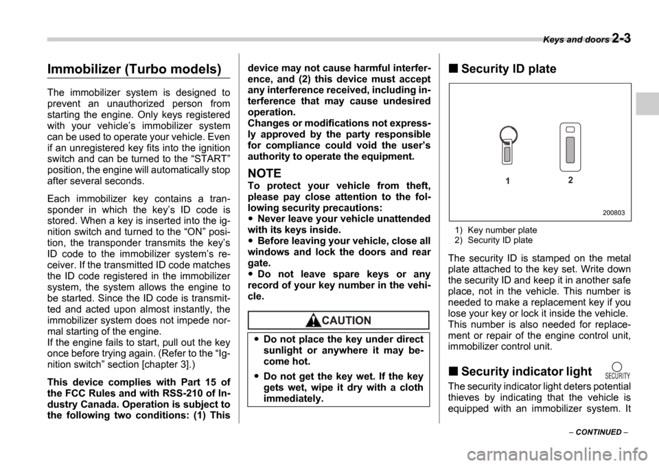
Security ID plate
1) Key number plate
2) Security ID plate
The security ID is stamped on the metal
plate attached to the key set. Write down
the security ID and keep it in another safe
place, not in the vehicle. This number is
needed to make a replacement key if you
lose your key or lock it inside the vehicle.
This number is also needed for replace-
ment or repair of the engine control unit,
immobilizer control unit.
Security indicator light
The security indicator light deters potential
thieves by indicating that the vehicle is
equipped with an immobilizer system. It
Do not place the key under direct
sunlight or anywhere it may be-
come hot.
Do not get the key wet. If the key
gets wet, wipe it dry with a cloth
immediately.
1 2
200803
Page 101 of 365
2-14 Keys and doors
cating that the system is now deactivated.
If the system was previously deactivated:
The odometer/trip meter screen displays AL on and the horn sounds once, indi-
cating that the system is now activated.
NOTE
You may have the above setting
change done by your SUBARU dealer.
If you have accidentally trig-
gered the alarm system
To stop the alarm
Do any of the following operations:
Press any button on the remote trans-
mitter.
Cycle the ignition switch from the
LOCK to ON position three times within
5 seconds.
Arming the system
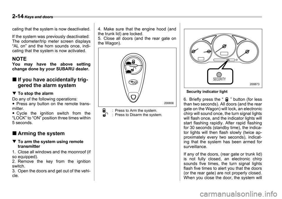
To arm the system using remote
transmitter
1. Close all windows and the moonroof (if
so equipped).
2. Remove the key from the ignition
switch.
3. Open the doors and get out of the vehi-
cle. 4. Make sure that the engine hood (and
the trunk lid) are locked.
5. Close all doors (and the rear gate on
the Wagon).
: Press to Arm the system.
: Press to Disarm the system.
Security indicator light
6. Briefly press the
button (for less
than two seconds). All doors (and the rear
gate on the Wagon) will lock, an electronic
chirp will sound once, the turn signal lights
will flash once, and the indicator lights will
start flashing rapidly. After rapid flashing
for 30 seconds (standby time), the indica-
tor lights will then flash slowly (twice ap-
proximately every two seconds), indicat-
ing that the system has been armed for
surveillance.
If any of the doors, (rear gate or trunk lid)
is not fully closed, an electronic chirp
sounds five times, the turn signal lights
flash five times to alert you that the doors
(or the rear gate) are not properly closed.
When you close the door, the system will200808
200873
Page 102 of 365
Keys and doors 2-15
CONTINUED
automatically arm and doors will automat-
ically lock.
To arm the system using power
door locking switches
1. Close all windows.
2. Remove the key from the ignition
switch.
3. Open the doors and get out of the vehi-
cle.
4. Make sure that the engine hood is
locked.
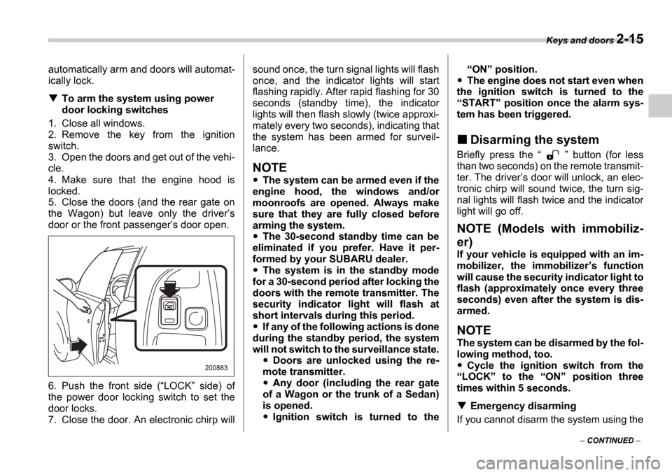
5. Close the doors (and the rear gate on
the Wagon) but leave only the driver s
door or the front passenger s door open.
6. Push the front side ( LOCK side) of
the power door locking switch to set the
door locks.
7. Close the door. An electronic chirp will sound once, the turn signal lights will flash
once, and the indicator lights will start
flashing rapidly. After rapid flashing for 30
seconds (standby time), the indicator
lights will then flash slowly (twice approxi-
mately every two seconds), indicating that
the system has been armed for surveil-
lance.
NOTE
The system can be armed even if the
engine hood, the windows and/or
moonroofs are opened. Always make
sure that they are fully closed before
arming the system.
The 30-second standby time can be
eliminated if you prefer. Have it per-
formed by your SUBARU dealer.
The system is in the standby mode
for a 30-second period after locking the
doors with the remote transmitter. The
security indicator light will flash at
short intervals during this period.
If any of the following actions is done
during the standby period, the system
will not switch to the surveillance state.
Doors are unlocked using the re-
mote transmitter.
Any door (including the rear gate
of a Wagon or the trunk of a Sedan)
is opened.
Ignition switch is turned to the
ON position.
The engine does not start even when
the ignition switch is turned to the START position once the alarm sys-
tem has been triggered.
Disarming the system
Briefly press the button (for less
than two seconds) on the remote transmit-
ter. The driver s door will unlock, an elec-
tronic chirp will sound twice, the turn sig-
nal lights will flash twice and the indicator
light will go off.
NOTE (Models with immobiliz-
er)
If your vehicle is equipped with an im-
mobilizer, the immobilizer s function
will cause the security indicator light to
flash (approximately once every three
seconds) even after the system is dis-
armed.
NOTE
The system can be disarmed by the fol-
lowing method, too.
Cycle the ignition switch from the
LOCK to the ON position three
times within 5 seconds.
Emergency disarming
If you cannot disarm the system using the
Page 114 of 365

3
Instruments and controls
Ignition switch .................................................... 3-3
LOCK .............................................. ......................... 3-3
ACC ............................................... ........................... 3-4
ON ................................................ ............................ 3-4
START ............................................. ......................... 3-4
Key reminder chime ................................ ............... 3-5
Ignition switch light ............................. ................... 3-5
Key interlock release (AT vehicles only) .......... .... 3-5
Hazard warning flasher ............................ .......... 3-6
Meters and gauges (WRX-STI) ....................... ... 3-6
Combination meter illumination .................... ........ 3-6
Cancelling sequential illumination of the combination meter ................................. .............. 3-6
Speedometer ....................................... .................... 3-6
Odometer/Trip meter ............................... ............... 3-7
Tachometer ........................................ ..................... 3-7
Fuel gauge ........................................ ....................... 3-8
Temperature gauge ................................. ............... 3-8
Outside temperature indicator ..................... ......... 3-9
REV indicator light and buzzer (WRX-STI) ....... 3-9 Setting the alarm-level engine speed .............. ..... 3-10
Deactivating the REV alarm system ................. ..... 3-11
Meters and gauges (Except WRX-STI) ............. 3-1 1
Speedometer ....................................... .................... 3-11
Odometer/Trip meter ............................... ............... 3-11
Tachometer ........................................ ..................... 3-12
Fuel gauge ........................................ ....................... 3-12
Temperature gauge ................................. ............... 3-13
Outside temperature indicator ..................... ......... 3-13Warning and indicator lights ......................
....... 3-14
Seatbelt warning light and chime .................. ........ 3-14
SRS airbag system warning light ................... ....... 3-15
Front passenger s frontal airbag ON and OFF
indicators ........................................ ...................... 3-15
CHECK ENGINE warning light/Malfunction indicator lamp .................................... ................... 3-16
Charge warning light .............................. ................ 3-16
Oil pressure warning light ........................ ............. 3-16
AT OIL TEMPerature warning light (AT vehicles) ..................................... .................... 3-17
Rear differential oil temperature warning light (WRX-STI) ......................................... ..................... 3-17
ABS warning light ................................. .................. 3-17
Brake system warning light ........................ ........... 3-18
Door open warning light ........................... ............. 3-19
All-Wheel Drive warning light (AWD AT vehicles
if equipped) ..................................... ................... 3-19
Intercooler water spray warning light (WRX-STI) ......................................... ..................... 3-19
Selector lever position indicator (AT vehicles) ... . 3-20
Turn signal indicator lights ...................... .............. 3-20
High beam indicator light ......................... .............. 3-20
Cruise control indicator light .................... ............. 3-20
Cruise control set indicator light ................ .......... 3-20
Driver s control center differential auto indicator
light (WRX-STI) ................................... .................. 3-20
Driver s control center differential indicator and
warning lights (WRX-STI) .......................... .......... 3-21
Headlight indicator light (WRX-STI) ............... ....... 3-21
REV indicator light (WRX-STI) ..................... .......... 3-21
Page 116 of 365
Instruments and controls 3-3
CONTINUED
Instrum ents and controlsIgnition switch
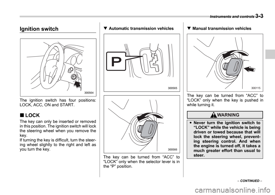
The ignition switch has four positions:
LOCK, ACC, ON and START.
LOCK
The key can only be inserted or removed
in this position. The ignition switch will lock
the steering wheel when you remove the
key.
If turning the key is difficult, turn the steer-
ing wheel slightly to the right and left as
you turn the key.
Automatic transmission vehicles
The key can be turned from ACC to
LOCK only when the selector lever is in
the P position.Manual transmission vehicles
The key can be turned from ACC to
LOCK only when the key is pushed in
while turning it.
300564
300565
300566
Never turn the ignition switch to LOCK while the vehicle is being
driven or towed because that will
lock the steering wheel, prevent-
ing steering control. And when
the engine is turned off, it takes a
much greater effort than usual to
steer.
300115
Page 117 of 365
3-4 Instruments and controls
NOTE
Keep the ignition switch in the
LOCK position when the engine is
not running.
Using electrical accessories for a
long time with the ignition switch in the ON or ACC position can cause the
battery to go dead.
If the ignition switch will not move from
the LOCK position to the ACC po-
sition, turn the steering wheel slightly
to the left and right as you turn the ig-
nition switch.
If the key is attached to a keyholder
or to a large bunch of other keys, cen-
trifugal force may act on it as the vehi-
cle moves, resulting in unwanted turn-
ing of the ignition switch. Also, if a
large keyholder is attached to the key,
your knees or hands may accidentally
touch it in a way that turns the ignition switch.
ACC
In this position the electrical accessories
(radio, cigarette lighter, etc.) can be used.
ON
This is the normal operating position after
the engine is started.
START
The engine is started in this position. The
starter cranks the engine to start it. When
the key is released (after the engine has
started), the key automatically returns to
the
ON position.
For vehicle with immobilizer
If your registered key fails to start the en-
gine, pull out the key once (the security in-
dicator light will blink), and then insert the
key in the ignition switch and turn it to the START position and again try to start the
engine.
NOTE
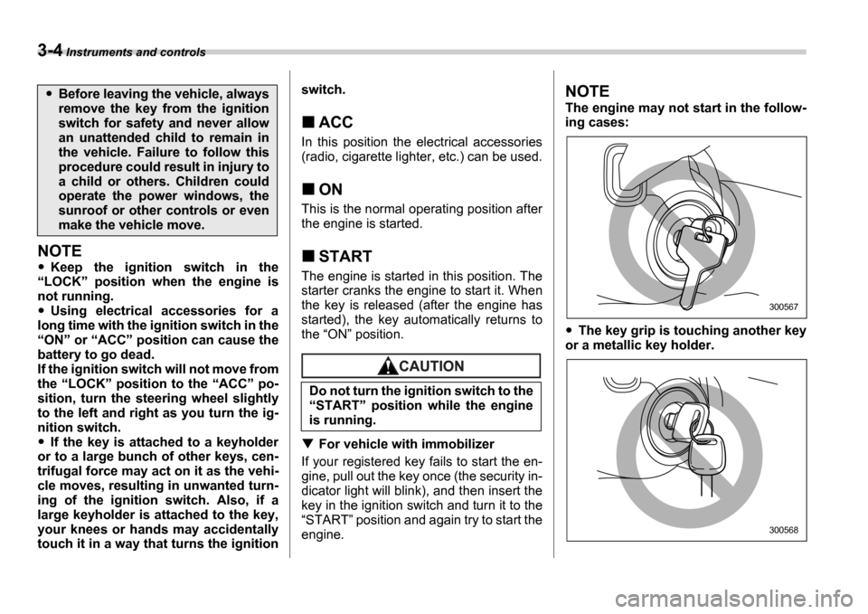
The engine may not start in the follow-
ing cases:
The key grip is touching another key
or a metallic key holder.
Before leaving the vehicle, always
remove the key from the ignition
switch for safety and never allow
an unattended child to remain in
the vehicle. Failure to follow this
procedure could result in injury to
a child or others. Children could
operate the power windows, the
sunroof or other controls or even
make the vehicle move.
Do not turn the ignition switch to the START position while the engine
is running.
300567
300568
Page 120 of 365
Instruments and controls 3-7
CONTINUED
Odometer/Trip meter
1) Trip meter
2) Odometer
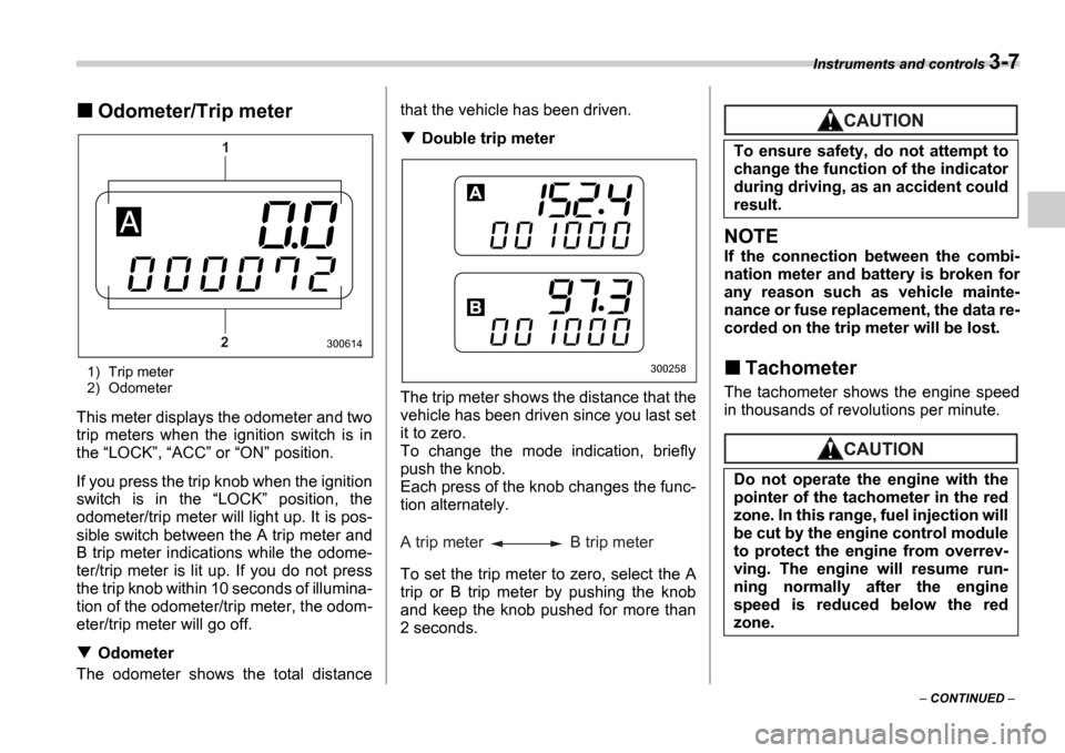
This meter displays the odometer and two
trip meters when the ignition switch is in
the LOCK , ACC or ON position.
If you press the trip knob when the ignition
switch is in the LOCK position, the
odometer/trip meter will light up. It is pos-
sible switch between the A trip meter and
B trip meter indications while the odome-
ter/trip meter is lit up. If you do not press
the trip knob within 10 seconds of illumina-
tion of the odometer/trip meter, the odom-
eter/trip meter will go off.
Odometer
The odometer shows the total distance that the vehicle has been driven.
Double trip meter
The trip meter shows the distance that the
vehicle has been driven since you last set
it to zero.
To change the mode indication, briefly
push the knob.
Each press of the knob changes the func-
tion alternately.
To set the trip meter to zero, select the A
trip or B trip meter by pushing the knob
and keep the knob pushed for more than
2 seconds.
NOTE
If the connection between the combi-
nation meter and battery is broken for
any reason such as vehicle mainte-
nance or fuse replacement, the data re-
corded on the trip meter will be lost.
Tachometer
The tachometer shows the engine speed
in thousands of revolutions per minute.
1
2
300614
300258
A trip meter B trip meter
To ensure safety, do not attempt to
change the function of the indicator
during driving, as an accident could
result.
Do not operate the engine with the
pointer of the tachometer in the red
zone. In this range, fuel injection will
be cut by the engine control module
to protect the engine from overrev-
ving. The engine will resume run-
ning normally after the engine
speed is reduced below the red
zone.