Page 9 of 56
POWER ASSISTED STEERING
Fault finding - Allocation of computer tracks36B
36B - 9V6 MR-366-X84-36B000$198_eng.mif
PAS
Vdiag No.: 04, 06, 08, 0C
and 12POWER ASSISTED STEERING
Fault finding - Allocation of computer tracks
ALLOCATION OF TRACKS
The computer is inseparable from the steering column assembly
EPAS computer (8-track black connector):
track 1Not used
track 2Not used
track 3Not used
track 4Multiplex line L1 signal
track 5Multiplex line L2 signal
track 6Multiplex line H1 signal
track 7Multiplex line H2 signal
track 8+ after ignition feed
EPAS computer (2-track black connector):
track 1permanent +
track 2earth
MR-366-X84-36B000$198_eng.mif
Page 10 of 56

POWER ASSISTED STEERING
Fault finding - Replacement of components36B
36B - 10V6 MR-366-X84-36B000$264_eng.mif
PAS
Vdiag No.: 04, 06, 08, 0C
and 12POWER ASSISTED STEERING
Fault finding - Replacement of components
The power-assisted steering computer cannot be separated from the steering column.
Before replacing the electric power assisted steering computer, the battery must be disconnected.
Procedure to follow after battery disconnection:
Every time the battery is disconnected, the steering wheel angle is invalid (remains at 0) and status ET020 is at
Status 3.
Following a road test, this will result in a fault in the Electronic Stability Program.
Therefore, every time the battery is disconnected, turn the steering wheel from lock to lock, then bring back the
steering wheel to the centre point with the wheels set straight ahead and the engine running.
Check that ET020 Steering wheel angle sensor programming becomes Status 4.
If the fault is still present, stop and restart the engine without pressing the ESP button and repeat the procedure
above.
Replacing the computer:
Each time the Electric Power Assisted Steering computer is replaced, configure the computer to the vehicle (see
SC001 Computer calibration) and program the steering wheel angle sensor (VP004 Steering wheel angle sensor
programming).
The computer must only be replaced with the battery disconnected.
MR-366-X84-36B000$264_eng.mif
Page 11 of 56

POWER ASSISTED STEERING
Fault finding - Configurations and programming36B
36B - 11V6 MR-366-X84-36B000$330_eng.mif
PAS
Vdiag No.: 04, 06, 08, 0C
and 12POWER ASSISTED STEERING
Fault finding - Configurations and programming
VP004: STEERING WHEEL ANGLE SENSOR PROGRAMMING
NOTESThis programming procedure is performed after replacing the EPAS computer.
WARNING
Programming the steering wheel angle sensor means programming the 0 angle (wheels straight ahead position).
It must be done for any blank computer, and every time it is requested in this note.
The absence of or incorrect programming of this sensor will illuminate the Service warning light and create an
Electronic Stability Program fault.
OPERATIONS TO PERFORM BEFORE PROGRAMMING
–With the ignition on or engine running (to obtain maximum steering assistance), turn the steering wheel to full
left lock and then to full right lock,
–position the vehicle with the wheels straight ahead and the steering at the centre point (driving in a straight line),
–run the command by pressing the CONFIRM button,
–while the COMMAND IN PROGRESS message is displayed, turn the steering wheel a quarter of a turn from left
to right.
–Once the COMMAND COMPLETE message is displayed, exit fault finding mode (close dialogue with the
computer without switching off the tool) and then switch off the vehicle's ignition for 15 seconds minimum for
the programming to be registered.
Note:
To obtain a precise position with the wheels set straight ahead (driving in a straight line), this operation must be
performed on a front axle adjustment bench (especially for vehicles fitted with ESP).
OPERATIONS TO PERFORM AFTER PROGRAMMING
–Switch on the ignition and establish dialogue with the EPAS computer,
–turn the steering wheel to full left lock and then to full right lock,
–check that the programming has been properly registered: ET020 Steering wheel angle sensor programming
should be STATUS 4,
–check the conformity of the angle value by consulting parameter PR121 Steering wheel angle,
–check that there are no faults,
–carry out the necessary repairs, consulting the fault finding manual.
IMPORTANT
If the vehicle is fitted with ESP, establish dialogue with the ABS/ESP computer after the operation; if the function
is available (depending on computer version) clear the ESP sensor programming using command RZ003.
Make sure there are no ESP faults: make the necessary repairs, consulting the fault finding manual.
MR-366-X84-36B000$330_eng.mif
Page 12 of 56

POWER ASSISTED STEERING
Fault finding - Configurations and programming36B
36B - 12V6 MR-366-X84-36B000$330_eng.mif
PAS
Vdiag No.: 04, 06, 08, 0C
and 12
SC001: COMPUTER CALIBRATION
NOTESThis configuration is performed after replacing the EPAS computer.
WARNING
The computer is supplied with the default calibration 0.
An incorrect configuration may damage the function.
Command SC001 is used to define the vehicle specifications.
The configuration is determined by the following specifications:
–Vehicle type:
–The diameter of the vehicle wheel rims:
–The vehicle engine type and gearbox type:
CALIBRATION PROCEDURE:
–Connect the diagnostic tool and select EPAS,
–select command SC001 Computer calibration,
–configure the computer in line with the vehicle definition,
–exit fault finding mode without switching off the tool (close the application only),
–switch off the ignition,
–wait 15 seconds for the end of power-Iatch then restart,
–make sure that the configuration reading corresponds to the desired calibration:
LC005 or ET026 Computer calibration.
Page 13 of 56
POWER ASSISTED STEERING
Fault finding - Configurations and programming36B
36B - 13V6 MR-366-X84-36B000$330_eng.mif
PAS
Vdiag No.: 04, 06, 08, 0C
and 12
LC005: COMPUTER CALIBRATION
Reading configuration LC005 enables you to check that the computer calibration corresponds with the vehicle type
undergoing fault finding.
The values of LC005 are interpreted in ET026 (see Interpretation of statuses).
If the calibration is not to your satisfaction, use command SC001 to redefine the vehicle specifications.
Page 14 of 56
POWER ASSISTED STEERING
Fault finding - Fault summary table36B
36B - 14V6 MR-366-X84-36B000$396_eng.mif
PAS
Vdiag No.: 04, 06, 08, 0C
and 12
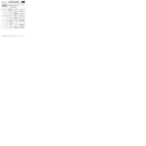
Fault finding - Fault summary table
Tool faultASSOCIATED FAULT
FINDING CODEDiagnostic tool title STATUS
DF00256 08Computer0D
DF02056 01Computer supply12
DF033D000Multiplex network0E
DF03556 06Variable power assisted steering motor0D
DF03856 05Angle sensor0D, 06
DF05356 02Computer configuration0D, 16
DF05456 04Torque sensor0D
DF05556 07Computer Memory0D
DF05756 09Vehicle speed multiplex signal0D, 0E
DF05956 03Angle sensor0D, 06
MR-366-X84-36B000$396_eng.mif
Page 15 of 56

POWER ASSISTED STEERING
Fault finding - Interpretation of faults
36B
36B - 15V6 MR-366-X84-36B000$462_eng.mif
PAS
Vdiag No.: 04, 06, 08, 0C
and 12POWER ASSISTED STEERING
Fault finding - Interpretation of faults
DF002
PRESENT
OR
STOREDCOMPUTER
DEF : Computer fault
WARNING
Consult the fault contexts.
If PR143 Internal fault codes = 46 and the battery voltage when the fault occurs (PR108) is above 9 V, do not
clear the fault; contact the Techline.
If PR143 Internal fault code = 46 and the battery voltage when the fault occurs (PR108) is less than or equal to
9 V, run fault finding on the battery and charge circuit and clear the fault.
For other values of PR143, do not clear the fault, contact the Techline.
NOTESConditions for applying the fault finding procedure to stored faults:
The fault is declared present after starting or a steering wheel movement from full lock
to full lock.
–Check the condition and connection of the battery terminals.
–Check that the EPAS black 2-track connector is correctly locked.
–Check that the EPAS black 8-track connector is correctly locked.
–Check the condition and conformity of the EPAS fuses: on the power fuse board (70A) and on the UPC (5A).
–Check the conformity of PR108 Computer feed voltage: 12 V < PR108 < 16 V.
Check that:
–there is a + 12 V before ignition feed on track 1 of the electric power steering black 2-track connector,
–there is an earth on track 2 of the electric power steering black 2-track connector,
–there is a + 12 V after ignition feed on track 8 of the steering column assembly black 8-track connector.
If there is a repair procedure (see Technical Note 6015A, Repairing electrical wiring, Wiring: Precautions for
repair), repair the wiring, otherwise change the wiring.
If the fault is still present, contact the Techline.
AFTER REPAIRCarry out a road test followed by a complete test with the diagnostic tool.
DAETRW_V04_DF002/DAETRW_V08_DF002/DAETRW_V06_DF002/DAETRW_V0C_DF002/
DAETRW_V12_DF002
MR-366-X84-36B000$462_eng.mif
Page 16 of 56

POWER ASSISTED STEERING
Fault finding - Interpretation of faults
36B
36B - 16V6 MR-366-X84-36B000$462_eng.mif
PAS
Vdiag No.: 04, 06, 08, 0C
and 12
DF020
PRESENT
OR
STOREDCOMPUTER SUPPLY VOLTAGE
DEF : Computer internal voltage
NOTESSpecial notes:
Although stored in the computer, this fault is not caused by an electric power-assisted
steering failure, but by a poor electrical supply.
Conditions for applying the fault finding procedure to stored faults:
The fault is declared present after the engine is started or a steering wheel movement
from full lock to full lock.
–Check the condition and connection of the battery terminals.
–Check that the EPAS black 2-track connector is correctly locked.
–Check that the EPAS black 8-track connector is correctly locked.
–Check the condition and conformity of the EPAS fuses: on the power fuse board (70A) and on the UPC (5A).
–Check the conformity of PR108 Computer feed voltage: 12 V < PR108 < 16 V.
Check that:
–there is a + 12 V before ignition feed on track 1 of the electric power steering black 2-track connector,
–there is an earth on track 2 of the electric power steering black 2-track connector,
–there is a + 12 V after ignition feed on track 8 of the steering column assembly black 8-track connector.
If there is a repair procedure (see Technical Note 6015A, Repairing electrical wiring, Wiring: Precautions for
repair), repair the wiring, otherwise change the wiring.
Check the voltage of the battery and the charge circuit.
Repair if necessary.
If the fault is still present, contact the Techline.
AFTER REPAIRCarry out a road test followed by a complete test with the diagnostic tool.
DAETRW_V04_DF020/DAETRW_V08_DF020/DAETRW_V06_DF020/DAETRW_V0C_DF020/
DAETRW_V12_DF020