2006 RENAULT SCENIC ESP
[x] Cancel search: ESPPage 3 of 86

MULTIMEDIA
Fault finding - Introduction
86C
86C-2
NAV 4R
Program no.: 0000
Vdiag No.: 24
To cut off the + after ignition feed, proceed as follows:
Faults
Faults are declared present or stored (depending on whether they appeared in a certain context and have
disappeared since, or whether they remain present but are not diagnosed within the current context).
The present or stored status of faults should be taken into consideration when the diagnostic tool is switched on
after the + after ignition feed (without any system components being active).
For a present fault, apply the procedure described in the Interpretation of faults section.
For a stored fault, note the faults displayed and apply the instructions in the Notes section.
If the fault is confirmed when the instructions in the Notes section are applied, the fault is present. Deal with the
fault.
If the fault is not confirmed, check:
–the electrical lines which correspond to the fault,
–the connectors on these lines (corrosion, bent pins, etc.),
–the resistance of the component detected as faulty,
–the condition of the wires (melted or split insulation, wear).
Conformity check
The aim of the conformity check is to check data that does not produce a fault on the diagnostic tool because the
data is inconsistent. Therefore, this stage is used to:
–carry out fault finding on faults that do not have a fault display, and which may correspond to a customer
complaint.
–check that the system is operating correctly and that there is no risk of a fault recurring after repairs.
This section gives the fault finding procedures for statuses and parameters and the conditions for checking them.
If a status is not behaving normally or a parameter is outside the permitted tolerance values, consult the
corresponding fault finding page.
Customer complaints - Fault finding chart
If the test with the diagnostic tool is OK but the customer complaint is still present, the fault should be processed by
customer complaints. For vehicles with key/radiofrequency remote control, use the key to switch off the ignition.
For vehicles with a Renault card,
press the Start button twice briefly (less than 3 seconds),
Ensure that the + after ignition feed has been cut off by checking that the computer indicator lights on the
instrument panel have gone out.
A synopsis of the general procedure to follow is provided on the following page in the
form of a flow chart.
Page 5 of 86

MULTIMEDIA
Fault finding - Introduction
86C
86C-4
NAV 4R
Program no.: 0000
Vdiag No.: 24
4. FAULT FINDING PROCEDURE (continued)
Wiring check
Fault finding problems
Disconnecting the connectors and/or manipulating the wiring harness may temporarily remove the cause of a fault.
Electrical measurements of voltage, resistance and insulation are generally correct, especially if the fault is not
present when the analysis is made (stored fault).
Visual inspection
Look for damage under the bonnet and in the passenger compartment.
Carefully check the fuses, insulation and wiring harness routing.
Look for signs of oxidation.
Tactile inspection
While manipulating the wiring harness, use the diagnostic tool to note any change in fault status from stored to
present.
Check that the connectors are properly locked.
Apply light pressure to the connectors.
Twist the wiring harness.
If there is a change in status, try to locate the source of the fault.
Inspection of each component
Disconnect the connectors and check the appearance of the clips and tabs, as well as the crimping (no crimping on
the insulating section).
Make sure that the clips and tabs are properly locked in the holes.
Check that no clips or tabs have been dislodged during connection.
Check the clip contact pressure using an appropriate model of tab.
Resistance check
Check the continuity of entire lines, then section by section.
Look for a short circuit to earth, to + 12 V or to another wire.
If a fault is detected, repair or replace the wiring harness.
Page 43 of 86

MULTIMEDIA
Fault finding - Interpretation of statuses
86C
86C-42
NAV 4R
Program no.: 0000
Vdiag No.: 24
ET006
ET007
ET008
ET009
ET010
ET036
CONTINUED 3
If the measured values do not correspond with the values above, replace the radio satellite control.
Mégane II ph2 (see MR 364 mechanical, 84A Control - Signals, Steering wheel controls: Removal -
Refitting).
Laguna II ph2 (see MR 395 mechanical, 84A Control - Signals, Steering wheel controls: Removal - Refitting).
Scénic II ph2 (see MR 370 mechanical, 84A Control - Signals, Steering wheel controls: Removal - Refitting).
Master ph2 and ph3
(see MR 377 mechanical, 86A, Radio control satellite: Removal - Refitting).
Master propulsion ph2
(see Technical Note 3818A, 86A, Radio, Radio control satellite: Removal - Refitting).
Trafic II ph1 and ph2
(see MR 408 mechanical, 86A, Radio control satellite: Removal - Refitting).
If the measurements are in order, contact the Techline.
AFTER REPAIRRepeat the conformity check from the start.
Page 52 of 86

MULTIMEDIA
Fault finding - Interpretation of parameters86C
86C-51
NAV 4R
Program no.: 0000
Vdiag No.: 24
PR006
CONTINUED
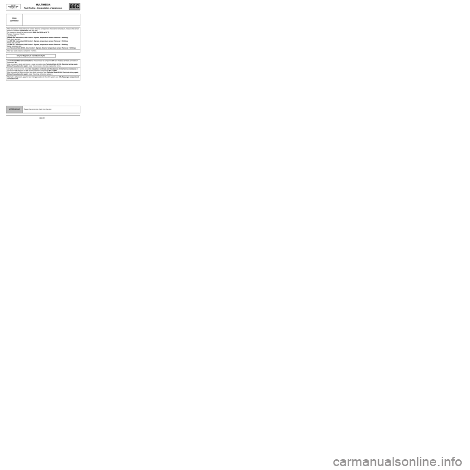
If the temperature measured by the sensor does not correspond to the exterior temperature, measure the sensor
resistance between connections 47C and 47D.
The resistance should be approximately 3000 ΩΩ Ω Ω
±± ± ±
300 ΩΩ Ω Ω
at 20 °° ° °
C.
Replace the sensor if faulty.
Laguna II ph2
(see MR 395 mechanical, 84A Control - Signals, temperature sensor: Removal - Refitting)
Trafic II ph1 and ph2
(see MR 408 mechanical, 84A Control - Signals, temperature sensor: Removal - Refitting)
Master ph2 and ph3
(see MR 377 mechanical, 84A Control - Signals, temperature sensor: Removal - Refitting)
Master propulsion ph2
(see Technical Note 3818A, 84A, Control - Signals, Exterior temperature sensor: Removal - Refitting)
If the fault is still present, contact the Techline.
Only for Mégane II ph 2 and Scénic II ph2
Check the condition and connection of the connector of component 645 and the black 24-track connector of
component 261.
If the connector is faulty and there is a repair procedure (see Technical Note 6015A, Electrical wiring repair,
Wiring: Precautions for repair), repair the connector, otherwise replace the wiring.
Using the universal bornier, check the insulation, continuity and the absence of interference resistance on
connection 47Z (Mégane) or 47C (Scénic) between components 261 and 645.
If the connection is faulty and there is a repair procedure (see Technical Note 6015A, Electrical wiring repair,
Wiring: Precautions for repair), repair the wiring, otherwise replace it.
If the fault is still present, apply the fault finding procedure for the UCH system (see 87B, Passenger compartment
connection unit).
AFTER REPAIRRepeat the conformity check from the start.
Page 56 of 86

MULTIMEDIA
Fault finding - Interpretation of parameters86C
86C-55
NAV 4R
Program no.: 0000
Vdiag No.: 24
*RDS: Radio Data SystemPR010
RADIO FIELD INTENSITY
NOTESThere must be no present or stored faults.
Engine stopped, ignition on.
Tune to a known FM or AM station with the vehicle in an open area if possible.
The "Radio field intensity" corresponds to the electrical intensity of the radio signal (FM or AM) received at the
radionavigation tuner input, at the frequency currently selected. It is expressed in dB µV.
It gives an indication of the radio reception level. Below 18 dB µV, the station is considered weak and does not
appear in the list of radio stations.
A low value (< 18 dB µV) on this parameter means that:
–Either the selected station has a weak transmission in the geographical area. This may be due to the
distance from the selected station's transmitter (far from urban area, on motorways) or obstacles interfering
with the transmission of radio waves (mountainous areas, buildings, deep valleys).
–Or, if the reception conditions are good in the geographical area for the selected station, there is a fault on
the vehicle's reception system: one of the components (aerial/aerial amplifier/coaxial connection/radio aerial
connector) is faulty. In this case, refer to ALP 4.
This parameter may be used to compare two vehicles in order to determine if there actually is a vehicle fault.
Summary table of field values and their effect on radio reception:
Radio field intensityAudio
qualityRDS* decoding
(eg.: station names display)Automatic tuning/
Presence in the radio list
PR010 > 18 dBµVOK OK OK
14 dBµV < PR010 < 18 dBµVOK OKNOK
10 dBµV < PR010 < 14 dBµVOKNOK NOK
PR010 < 10 dBµVNOK NOK NOK
AFTER REPAIRRepeat the conformity check from the start.
NAV4R_V24_PR010
Page 81 of 86

MULTIMEDIA
Diagnostic - Fault finding chart86C
86C-80
NAV 4R
Program no.: 0000
Vdiag No.: 24
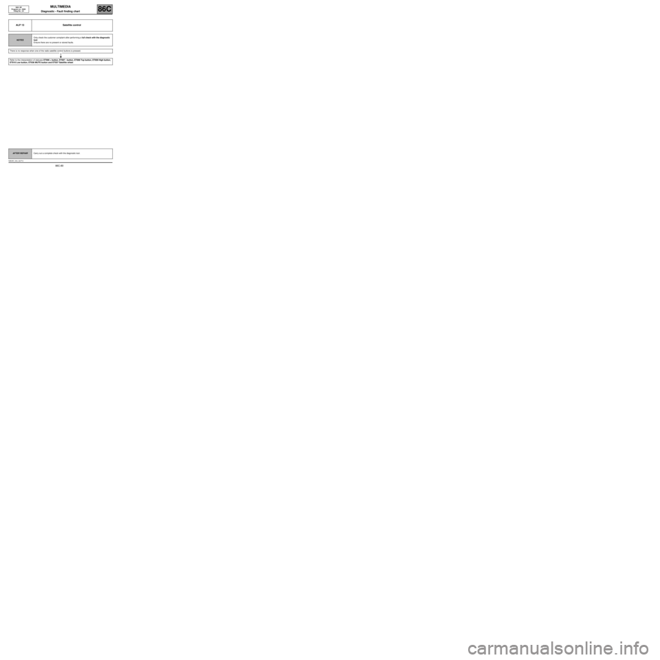
ALP 13 Satellite control
NOTESOnly check the customer complaint after performing a full check with the diagnostic
tool.
Ensure there are no present or stored faults.
There is no response when one of the radio satellite control buttons is pressed.
Refer to the interpretation of statuses ET006 + button, ET007 - button, ET008 Top button, ET009 High button,
ET010 Low button, ET036 MUTE button and ET037 Satellite wheel.
AFTER REPAIRCarry out a complete check with the diagnostic tool.
NAV4R_V24_ALP13