Page 13 of 281
1. Power steering fluid reservoir (P.8-14)
2. Engine oil filler cap (P.8-11)
3. Automatic transmission fluid dipstick
(*1) (P.8-13)
4. Brake and clutch (*2) fluid reservoir
(P.8-14)
5. Air cleaner (P.8-18)
6. Window washer fluid reservoir (P.8-15)
7. Engine coolant reservoir (P.8-8)
8. Engine oil dipstick (P.8-10)
9. Radiator cap (P.8-9)
10. Fuse/Fusible link holder (P.8-22)
11. Battery (P.8-16)
*1: For Automatic Transmission (AT) model
*2: For Manual Transmission (MT) model
SDI1947
ENGINE COMPARTMENT CHECK
LOCATIONS0-8
Illustrated table of contents
�
06.4.14/T30-J/V5.0
�
Page 17 of 281
LUMBAR SUPPORT (for driver’s
seat)The lumbar support feature provides lower back
support to the driver.
Turn the lever forward or backward to adjust the
seat lumbar area.
FRONT POWER SEAT
ADJUSTMENT (if so equipped for
driver’s seat)
WARNING
�Do not adjust the driver’s seat while
driving so full attention may be given
to vehicle operation.
�Do not leave children unattended in-
side the vehicle. They could unknow-
ingly activate switches or controls.
Unattended children could become
involved in serious accidents.Operating tips�The seat motor has an auto-reset overload
protection circuit. If the motor stops during
operation, wait 30 seconds, then reactivate
the switch.
�Do not operate the power support seat
for a long period of time when the engine is
off. This will discharge the battery.
SPA1729A
1-4
Safety — Seats, seat belts and supplemental restraint system
�
06.4.14/T30-J/V5.0
�
Page 81 of 281
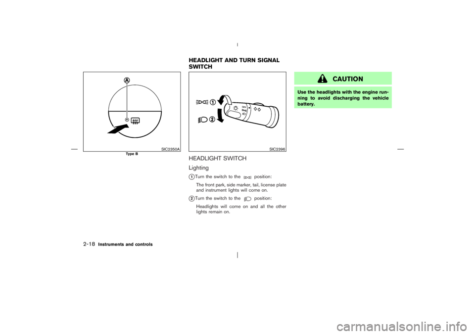
HEADLIGHT SWITCH
Lighting
�1Turn the switch to the
position:
The front park, side marker, tail, license plate
and instrument lights will come on.
�2Turn the switch to the
position:
Headlights will come on and all the other
lights remain on.
CAUTION
Use the headlights with the engine run-
ning to avoid discharging the vehicle
battery.
SIC2350A
Type B
SIC2396
HEADLIGHT AND TURN SIGNAL
SWITCH
2-18
Instruments and controls
�
06.4.14/T30-J/V5.0
�
Page 85 of 281

To sound the horn, push the center pad area
�1
of the steering wheel.
WARNING
Do not disassemble the horn. Doing so
could affect proper operation of the
supplemental front air bag system. Tam-
pering with the supplemental front air
bag system may result in serious per-
sonal injury.The front seats are warmed by built-in heaters.
The switches located on the center console can
be operated independently (driver’s side seat
�A
and front passenger’s side seat
�B) of each
other.
1. Start the engine.
2. Select heat range.
�For high heat, press the(High) side
�1
of the switch.
�For low heat, press the
(Low) side
�2
of the switch.
�For no heat, the switch has a center OFF
position
�3
between low and high.The indicator light
�C
in the switch will
illuminate when low or high is selected.
The heater is controlled by a thermostat,
automatically turning the heater on and off.
The indicator light will remain on as long as
the switch is on.
3. When the vehicle’s interior is warmed, or
before you leave the vehicle, be sure to turn
the switch to the off position (center).
CAUTION
�The battery could be discharged if
the seat heater is operated while the
engine is not running.
�Do not use the seat heater for ex-
tended periods or when no one is
using the seat.
�Do not put anything on the seat
which insulates heat, such as a blan-
ket, cushion, seat cover, etc. Other-
wise, the seat may become over-
heated.
�Do not place anything hard or heavy
on the seat or pierce it with a pin or
SIC0987A
SIC2056
HORNHEATED SEATS (if so equipped)2-22
Instruments and controls
�
06.4.14/T30-J/V5.0
�
Page 89 of 281

CAUTION
�The outlet and plug may be hot dur-
ing or immediately after use.
�This power outlet is not designed for
use with a cigarette lighter unit.
�Do not use with accessories that ex-
ceed a 12 volt, 120W (10A) power
draw. Do not use double adapters or
more than one electrical accessory.�Use only one power outlet at a time.
�Use power outlets with the engine
running to avoid discharging the ve-
hicle battery. (If the engine is
stopped, this could result in a dis-
charged battery.)
�Avoid using when the air conditioner,
headlights or rear window defroster
is on.
�Before inserting or disconnecting a
plug, be sure to turn off the power
switch of electrical accessory being
used or the ACC power of the vehicle.
�Push the plug in as far as it will go. If
good contact is not made, the plug
may overheat or the internal tem-
perature fuse may blow.
�When not in use, be sure to replace
the cover. Do not allow water to con-
tact the socket.
DRIVER’S BOXTo open the driver’s box, push the button and
pull up the lid.
To close, push the lid down.
WARNING
Keep the lid of the box closed while
driving to help prevent injury in an acci-
dent or a sudden stop.
SIC1710A
Luggage room
SIC2400
STORAGE
2-26
Instruments and controls
�
06.4.14/T30-J/V5.0
�
Page 103 of 281
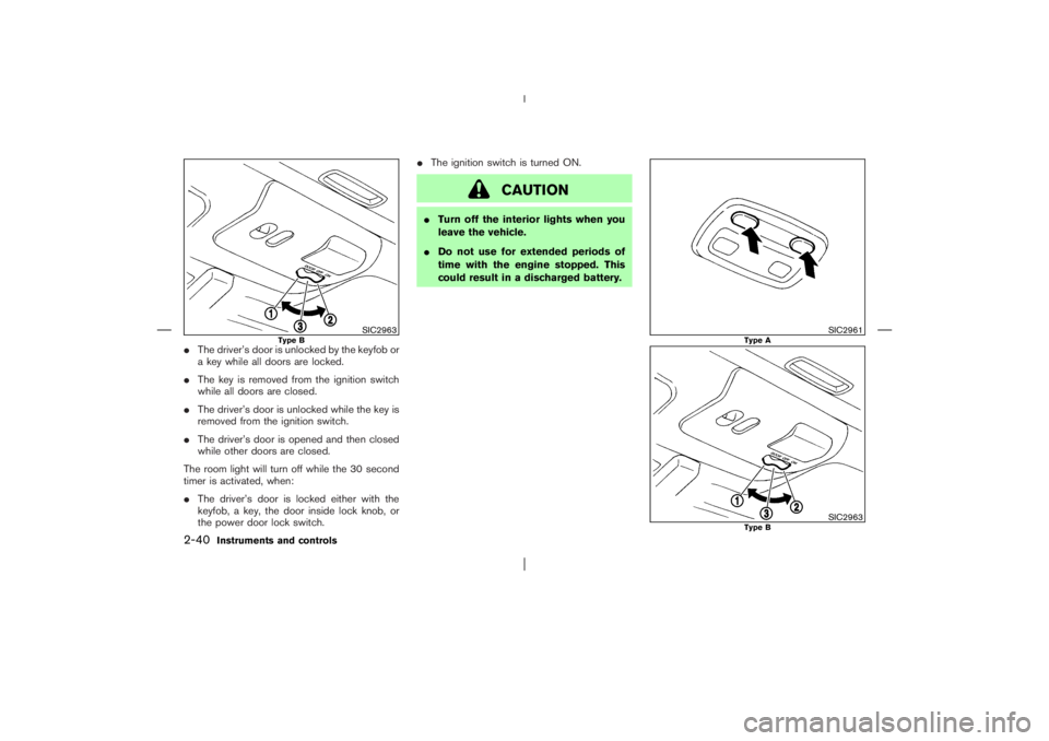
�The driver’s door is unlocked by the keyfob or
a key while all doors are locked.
�The key is removed from the ignition switch
while all doors are closed.
�The driver’s door is unlocked while the key is
removed from the ignition switch.
�The driver’s door is opened and then closed
while other doors are closed.
The room light will turn off while the 30 second
timer is activated, when:
�The driver’s door is locked either with the
keyfob, a key, the door inside lock knob, or
the power door lock switch.�The ignition switch is turned ON.
CAUTION
�Turn off the interior lights when you
leave the vehicle.
�Do not use for extended periods of
time with the engine stopped. This
could result in a discharged battery.
SIC2963
Type B
SIC2961
Type A
SIC2963
Type B
2-40
Instruments and controls
�
06.4.14/T30-J/V5.0
�
Page 104 of 281

MAP LIGHTType A:
To turn on the map light, push the switch in, and
the light illuminates. To turn off, push the switch
again.
CAUTION
�Turn off the interior lights when you
leave the vehicle.
�Do not use for extended periods of
time with the engine stopped. This
could result in a discharged battery.
Type B:
The map light has a three-position switch.
When the switch is in the “DOOR” position
�1,
the light illuminates when a door is opened.
When the map light switch is in the “ON”
position
�2, the map light will illuminate.
When the switch is in the “OFF” position
�3, the
map light does not illuminate.
LUGGAGE ROOM LIGHTThe luggage room light has a three-position
switch.
When the switch is in the center position
�2, the
light will illuminate when a door (including the
back door) is opened.
When the switch is in the “ON” position
�1, the
light will illuminate.
When the switch is in the “OFF” position
�3, the
light will turn off.
Interior light timerTimer function works the same as the room light.See “Room light” earlier in this section.
CAUTION
�Turn off the interior lights when you
leave the vehicle.
�Do not use for extended periods of
time with the engine stopped. This
could result in a discharged battery.
SIC2960
Instruments and controls
2-41
�
06.4.14/T30-J/V5.0
�
Page 106 of 281

3 Pre-driving checks and adjustmentsKeys ......................................................................................... 3-2
NISSAN Vehicle Immobilizer System keys ............... 3-2
Door locks .............................................................................. 3-3
Locking with key ............................................................. 3-3
Locking with inside lock knob..................................... 3-3
Locking with power door lock switch ....................... 3-4
Child safety rear door lock ........................................... 3-4
Remote keyless entry system ............................................ 3-5
How to use remote keyless entry system ................ 3-5
Battery replacement ....................................................... 3-6
Hood ........................................................................................ 3-7Back door ............................................................................... 3-7
Fuel-filler door ....................................................................... 3-9
Opening fuel-filler door ................................................. 3-9
Fuel-filler cap ................................................................... 3-9
Steering wheel .................................................................... 3-10
Tilt operation .................................................................. 3-10
Mirrors ................................................................................... 3-11
Inside rearview mirror .................................................. 3-11
Outside rearview mirrors ............................................ 3-12
Vanity mirror ................................................................... 3-13
�
06.4.14/T30-J/V5.0
�

2. Engine oil filler cap (P.8-11)
3. Automatic transmission fluid dipstick
(*1) (P.8-13)
4. Brake and clutch (*2) fluid reservoir
(P.8-14)
5. Air cleaner (P.")
The lumbar support feature provides lower back
support to the driver.
Turn the lever forward or backward to adjust the
seat lumbar area.
FRONT POWER SEAT
ADJUSTMENT")