Page 4 of 281
Table of
Contents
Illustrated table of contentsSafety — Seats, seat belts and supplemental
restraint systemInstruments and controlsPre-driving checks and adjustmentsDisplay screen, heater, air conditioner and audio
systemsStarting and drivingIn case of emergencyAppearance and careMaintenance and do-it-yourselfTechnical and consumer informationIndex
�
06.4.14/T30-J/V5.0
�
Page 60 of 281
SUPPLEMENTAL AIR BAG
WARNING LABELSWarning labels about the supplemental air bag
system are placed in the vehicle as shown in the
illustration.
SUPPLEMENTAL AIR BAG
WARNING LIGHTThe supplemental air bag warning light, display-
ing
in the instrument panel, monitors the
circuits of the supplemental front air bag,
supplemental side air bag system, and pre-
tensioner seat belt. The circuits monitored by the
air bag warning light are the diagnosis sensor
unit, satellite sensors, front air bag modules, side
air bag modules, and pre-tensioner seat belt and
all related wiring.
After turning the ignition key to the ON position,
the supplemental air bag warning light illumi-
nates. The supplemental air bag warning light
SPA0945B
SPA1097
Safety — Seats, seat belts and supplemental restraint system
1-47
�
06.4.14/T30-J/V5.0
�
Page 67 of 281

SPEEDOMETER AND ODOMETER
SpeedometerThe speedometer indicates vehicle speed.Odometer/Twin trip odometerThe odometer
�1/twin trip odometer
�2
are
displayed when the ignition switch is in the ON
position.
The odometer records the total distance the
vehicle has been driven.
The twin trip odometer records the distance of
individual trips.Changing the display:
Push the reset knob
�3
to change the trip
odometer display as follows:
TRIP A→TRIP B→CLOCK
→TEM-
PERATURE (Outside air — °C)→TRIP A
Resetting the trip odometer:
Push the reset knob
�3
for more than 1 second
to reset the trip odometer to zero.
Outside air temperature displayWhen the outside air temperature is 3°C or
lower, the display blinks to give a warning.
If the outside air temperature becomes 3°C or
lower when the display is in one of the other
modes, the display switches to the outside air
temperature display mode and blinks. If the
outside air temperature becomes above 3°C or
the display mode is not switched for 1 minute, it
returns to the display mode previously set.
Even while the display is blinking, the display
mode can be switched to the one previously set
by pushing the reset knob.
The ambient temperature sensor is located in
front of the radiator. The sensor may be affected
by road or engine heat, wind directions and
other driving conditions. The display may differ
from the actual ambient temperature or thetemperature displayed on various signs or bill-
boards.
Clock displayRefer to “Clock” later in this section for further
details on the clock adjustment.
SIC2395
2-4
Instruments and controls
�
06.4.14/T30-J/V5.0
�
Page 87 of 281
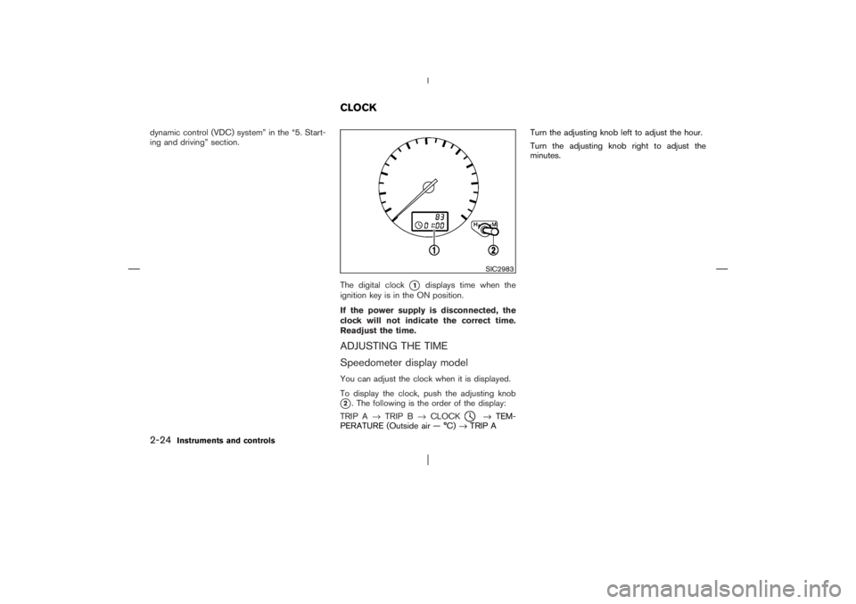
dynamic control (VDC) system” in the “5. Start-
ing and driving” section.
The digital clock
�1
displays time when the
ignition key is in the ON position.
If the power supply is disconnected, the
clock will not indicate the correct time.
Readjust the time.
ADJUSTING THE TIME
Speedometer display modelYou can adjust the clock when it is displayed.
To display the clock, push the adjusting knob�2. The following is the order of the display:
TRIP A→TRIP B→CLOCK
→TEM-
PERATURE (Outside air — °C)→TRIP ATurn the adjusting knobleft to adjust the hour.
Turn the adjusting knobright to adjust the
minutes.SIC2983
CLOCK
2-24
Instruments and controls
�
06.4.14/T30-J/V5.0
�
Page 88 of 281
Audio display model1. Turn the audio unit on by pushing the “PWR”
button
�1.
2. Push the “MENU” button
�2
until the display
indicates the clock adjustment mode.
If the “CLOCK OFF” is indicated on the display,
push the “TUNE” button
�3to change the mode
to “CLOCK ON”. Then push the “MENU” button
�2.
The time indicator will flash.
3. Push the “SEEK TRACK” button
�4to adjust
the hour.Push the “TUNE” button
�3
to adjust the
minute.
Pushing the
,
buttons will ad-
vance and
,
buttons will turn back
the time.
4. Push the “MENU” button
�2
to finish the
adjustment.
The power outlet is for powering electrical ac-
cessories such as cellular telephones.
SIC2981
SIC2276A
Front
POWER OUTLET
Instruments and controls
2-25
�
06.4.14/T30-J/V5.0
�
Page 121 of 281

WARNING
�Positioning of the heating or air con-
ditioning controls and display con-
trols should not be done while driv-
ing, in order that full attention may
be given to driving operation.
�Do not disassemble or modify this
system. If you do, it may result in
accidents, fire, or electric shock.
�Do not use this system if you notice
any abnormality, such as a frozen
screen or lack of sound. Continued
use of the system may result in acci-
dent, fire or electric shock.
�In case you notice any foreign object
in the system hardware, spill liquid
on it, or notice smoke or smell com-
ing from it, stop using the system
immediately and contact a NISSAN
dealer. Ignoring such conditions may
lead to accidents, fire, or electric
shock.When you use this system, make sure the engine
is running.
If you use the system with the engine not
running (ignition ONor ACC) for a long
time, it will use up all the battery power,
and the engine will not start.
Reference symbols:
“ENTER”button
This is a button on the control panel.
“Display”key
This is a select key on the screen. By selecting
this key you can proceed to the next function.
NAMES OF THE COMPONENTS1. “SETTING” button
2. “INFO” button
3. “
” brightness control button
4. “PREVIOUS” button
5. JOYSTICK and “ENTER” button
For navigation system control buttons (other
than above); refer to the separate Navigation
System Owner’s Manual.
SAA1275
SAFETY NOTE
CONTROL PANEL BUTTONS —
WITH NAVIGATION SYSTEM4-2
Heater, air conditioner and audio systems
�
06.4.14/T30-J/V5.0
�
Page 122 of 281

HOW TO USE JOYSTICK AND
“ENTER” BUTTONChoose an item on the display using the joystick
and push the “ENTER” button for operation.HOW TO USE “PREVIOUS”
BUTTONThis button has two functions.
To return to the previous screen:
When this button is pressed during setup, setup
will be canceled, and the screen will return to the
previous screen.
To finish the set-up:
When this button is pressed after setup is
completed, the settings will be renewed as
directed, and the screen will return to the map.
INFO:
When the “PREVIOUS” button must be
pressed, (for example, after the setup is finished)
instructions are given in the operation procedure
of each section in this manual. If the “PREVI-
OUS” button is pressed when not finished with
the setup, the setting will be canceled, and the
screen will return to the previous screen.
SETTING UP THE START-UP
SCREENWhen you turn the ignition key to ACC, the
SYSTEM START-UP warning is displayed on
the screen. Read the warning and select the
“I AGREE” (English) or “ENTER” (Franc¸ ais) key
then push the “ENTER” button.
If you do not push the “ENTER” button, this
system will not proceed to the next step display.
To proceed to the next step, refer to the separate
Navigation System Owner’s Manual.
HOW TO USE THE “INFO” BUTTONWhen the “INFO” button is pushed, the “MAIN-
TENANCE INFO.” screen will be displayed.Maintenance informationTo set the maintenance interval for the Engine
Oil or Oil Filter, choose an item using the joystick
and push the “ENTER” button.
You can also set to display a message to remind
you that the maintenance needs to be per-
formed.
The following example shows how to set the
engine oil change interval. Use the same steps
to set the other maintenance information.
SAA1276
Heater, air conditioner and audio systems
4-3
�
06.4.14/T30-J/V5.0
�
Page 123 of 281
 of the maintenance
schedule. To determine the recommended
maintenance interval, refer to your “NISSAN
S")
1. Reset the driving distance to the new main-
tenance schedule.
2. Set the interval (mileage) of the maintenance
schedule. To determine the recommended
maintenance interval, refer to your “NISSAN
Service and Maintenance Guide”.
3. To display the MAINTENANCE INFORMA-
TION automatically when the set trip distance
is reached, highlight the “Display Mainte-
nance Notification” key with the joystick and
push the “ENTER” button.
4. To return the display to MAINTENANCE
INFO., push the “PREVIOUS” button.Maintenance information display cannot be op-
erated when the vehicle is moving. Stop the
vehicle in a safe place to see the information.
Maintenance notificationThe “MAINTENANCE NOTIFICATION” screen
(“ENGINE OIL” or “OIL FILTER”) will be auto-
matically displayed as shown when both of the
following conditions are met:
�the vehicle is driven the set distance and the
ignition switch is turned OFF.
�the ignition switch is turned ON the next time
the vehicle will be driven.
To return to the previous display after the
“MAINTENANCE NOTIFICATION” screen is
displayed, push the “PREVIOUS” button.
SAA1277
SAA0968
4-4
Heater, air conditioner and audio systems
�
06.4.14/T30-J/V5.0
�