Page 2153 of 2896
![NISSAN VERSA 2006 Workshop Service Repair Manual TROUBLE DIAGNOSES WORK FLOW
LAN-27
[CAN FUNDAMENTAL]
C
D
E
F
G
H
I
J
L
MA
B
LAN
Revision: June 20062007 Versa
2. CAN DIAG SUPPORT MNTR: Check each item on “CAN DIAG SUPPORT MNTR”. Draw a line on t NISSAN VERSA 2006 Workshop Service Repair Manual TROUBLE DIAGNOSES WORK FLOW
LAN-27
[CAN FUNDAMENTAL]
C
D
E
F
G
H
I
J
L
MA
B
LAN
Revision: June 20062007 Versa
2. CAN DIAG SUPPORT MNTR: Check each item on “CAN DIAG SUPPORT MNTR”. Draw a line on t](/manual-img/5/57401/w960_57401-2152.png)
TROUBLE DIAGNOSES WORK FLOW
LAN-27
[CAN FUNDAMENTAL]
C
D
E
F
G
H
I
J
L
MA
B
LAN
Revision: June 20062007 Versa
2. CAN DIAG SUPPORT MNTR: Check each item on “CAN DIAG SUPPORT MNTR”. Draw a line on the
diagnosis sheet to indicate the error circuit.
a. Reception item of “ENGINE”: On “TCM”, “UNKWN” is indicated. This means ECM cannot receive the sig-
nal from TCM. Draw a line to indicate an error between ECM and TCM (line 2-a in the figure).
NOTE:
If “UNKWN” is indicated on “TRANSMIT DIAG”, then the control unit cannot transmit CAN communication
signal to each unit. Draw a line between the control unit and the splice.
b. Reception item of “ADAPTIVE LIGHT”: On “TCM”, “UNKWN” is indicated. This means AFS cannot
receive the signal from TCM. Draw a line to indicate an error between AFS and TCM (line 2-b in the fig-
ure).
c. Reception item of “MULTI AV”: “UNKWN” is not indicated. This indicates normal communication between
AV and its receiving units. Do not draw any line.
SKIB8725E
Page 2160 of 2896
![NISSAN VERSA 2006 Workshop Service Repair Manual LAN-34
[CAN FUNDAMENTAL]
TROUBLE DIAGNOSES WORK FLOW
Revision: June 20062007 Versa
2. CAN DIAG SUPPORT MNTR (with PAST): Check the CAN DIAG SUPPORT MNTR (with PAST) of units
indicating “U1000” or NISSAN VERSA 2006 Workshop Service Repair Manual LAN-34
[CAN FUNDAMENTAL]
TROUBLE DIAGNOSES WORK FLOW
Revision: June 20062007 Versa
2. CAN DIAG SUPPORT MNTR (with PAST): Check the CAN DIAG SUPPORT MNTR (with PAST) of units
indicating “U1000” or](/manual-img/5/57401/w960_57401-2159.png)
LAN-34
[CAN FUNDAMENTAL]
TROUBLE DIAGNOSES WORK FLOW
Revision: June 20062007 Versa
2. CAN DIAG SUPPORT MNTR (with PAST): Check the CAN DIAG SUPPORT MNTR (with PAST) of units
indicating “U1000” or “U1001” on SELF-DIAG RESULTS. Draw a line on the diagnosis sheet to indicate
the possible error circuit.
NOTE:
For the details of each indication on CAN DIAG SUPPORT MNTR, refer to LAN-44, "
CAN Diagnostic Sup-
port Monitor" .
a. Reception item of “ENGINE”: “VDC/TCS/ABS”, “3” is indicated in the “PAST”. This means ECM could not
receive the signal from ABS in the past. Draw a line between ECM and ABS (line 2-a in the figure).
b. Reception item of “METER”: “VDC/TCS/ABS”, “3” is indicated in the “PAST”. This means M&A could not
receive the signal from ABS in the past. Draw a line between M&A and ABS (line 2-b in the figure).
c. Reception item of “TRANSMISSION”: “VDC/TCS/ABS”, “3” is indicated in the “PAST”. This means TCM
could not receive the signal from ABS in the past. Draw a line between TCM and ABS (line 2-c in the fig-
ure).
SKIB8732E
Page 2173 of 2896
TROUBLE DIAGNOSIS
LAN-47
[CAN]
C
D
E
F
G
H
I
J
L
MA
B
LAN
Revision: June 20062007 Versa
CAN System Specification ChartUKS005VP
Check CAN system type from the following specification chart. Then choose the correct diagnosis sheet.
NOTE:
Refer to LAN-19, "
CHECK OF CAN SYSTEM TYPE (HOW TO USE CAN SYSTEM TYPE SPECIFICATION
CHART)" for how to use CAN system specification chart.
X: Applicable
VEHICLE EQUIPMENT IDENTIFICATION INFORMATION
NOTE:
Check CAN system type from the vehicle shape and equipment.
Body type Hatchback
Axle2WD
EngineMR18DE
Transmission M/T A/T CVT
Brake control — ABS — ABS — ABS
Intelligent Key system×× ××
CAN system type 12345678910
Diagnosis sheetLAN-
60
LAN-
61
LAN-
62
LAN-
63
LAN-
64
LAN-
65
LAN-
66
LAN-
67
LAN-
68
LAN-
69
CAN communication signal chartLAN-48, "TYPE 1/TYPE 2/TYPE 3/
TYPE 4"
LAN-49, "TYPE
5/TYPE 6"
LAN-50, "TYPE 7/TYPE 8/TYPE 9/
TYPE 10"
BKIA0210E
Page 2221 of 2896

HEADLAMP (FOR USA)
LT-13
C
D
E
F
G
H
I
J
L
MA
B
LT
Revision: June 20062007 Versa
Note 1: Vehicles without daytime light system may display this item, but cannot monitor it.
ACTIVE TEST
Display Item List
SELF-DIAGNOSTIC RESULTS
Display Item List
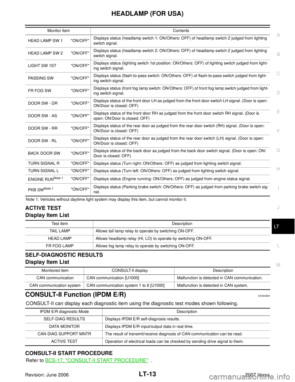
CONSULT-II Function (IPDM E/R)EKS00IMA
CONSULT-II can display each diagnostic item using the diagnostic test modes shown following.
CONSULT-II START PROCEDURE
Refer to BCS-17, "CONSULT-II START PROCEDURE" .
HEAD LAMP SW 1 "ON/OFF"Displays status (headlamp switch 1: ON/Others: OFF) of headlamp switch 2 judged from lighting
switch signal.
HEAD LAMP SW 2 "ON/OFF"Displays status (headlamp switch 2: ON/Others: OFF) of headlamp switch 2 judged from lighting
switch signal.
LIGHT SW 1ST "ON/OFF"Displays status (lighting switch 1st position: ON/Others: OFF) of lighting switch judged from light-
ing switch signal.
PASSING SW "ON/OFF"Displays status (flash-to-pass switch: ON/Others: OFF) of flash-to-pass switch judged from light-
ing switch signal.
FR FOG SW "ON/OFF"Displays status (front fog lamp switch: ON/Others: OFF) of front fog lamp switch judged from light-
ing switch signal.
DOOR SW - DR "ON/OFF"Displays status of the front door LH as judged from the front door switch LH signal. (Door is open:
ON/Door is closed: OFF)
DOOR SW - AS "ON/OFF"Displays status of the front door RH as judged from the front door switch RH signal. (Door is
open: ON/Door is closed: OFF)
DOOR SW - RR "ON/OFF"Displays status of the rear door as judged from the rear door switch (RH) signal. (Door is open:
ON/Door is closed: OFF)
DOOR SW - RL "ON/OFF"Displays status of the rear door as judged from the rear door switch (LH) signal. (Door is open:
ON/Door is closed: OFF)
BACK DOOR SW "ON/OFF"Displays status of the back door as judged from the back door switch signal. (Door is open: ON/
Door is closed: OFF)
TURN SIGNAL R "ON/OFF" Displays status (Turn right: ON/Others: OFF) as judged from lighting switch signal.
TURN SIGNAL L "ON/OFF" Displays status (Turn left: ON/Others: OFF) as judged from lighting switch signal.
ENGINE RUN
Note 1"ON/OFF" Displays status (Engine running: ON/Others: OFF) as judged from engine status signal.
PKB SW
Note 1"ON/OFF"Displays status (Parking brake switch: ON/Others: OFF) as judged from parking brake switch sig-
nal. Monitor item Contents
Te s t i t e m D e s c r i p t i o n
TAIL LAMP Allows tail lamp relay to operate by switching ON-OFF.
HEAD LAMP Allows headlamp relay (HI, LO) to operate by switching ON-OFF.
FR FOG LAMP Allows fog lamp relay to operate by switching ON-OFF.
Monitored item CONSULT-ll display Description
CAN communication CAN communication [U1000] Malfunction is detected in CAN communication.
CAN communication system CAN communication system 1 to 6 [U1000] Malfunction is detected in CAN system.
IPDM E/R diagnostic Mode Description
SELF-DIAG RESULTS Displays IPDM E/R self-diagnosis results.
DATA MONITOR Displays IPDM E/R input/output data in real time.
CAN DIAG SUPPORT MNTR The result of transmit/receive diagnosis of CAN communication can be read.
ACTIVE TEST Operation of electrical loads can be checked by sending drive signal to them.
Page 2231 of 2896
HEADLAMP (FOR USA)
LT-23
C
D
E
F
G
H
I
J
L
MA
B
LT
Revision: June 20062007 Versa
3. CHECKING CAN COMMUNICATIONS BETWEEN BCM AND IPDM E/R
Select “BCM” on CONSULT-II, and perform self-diagnosis for
“BCM”.
Display of self
-diagnosis results
NO DTC>> Replace IPDM E/R. Refer to PG-29, "Removal and
Installation of IPDM E/R" .
CAN COMM CIRCUIT>> Refer to LAN-44, "
TROUBLE DIAGNO-
SIS" .
Aiming AdjustmentEKS00IMG
PREPARATION BEFORE ADJUSTING
Before performing aiming adjustment, check the following.
1. Keep all tires inflated to correct pressures.
2. Place vehicle on level surface.
3. Set that there is no-load in vehicle other than the driver (or equivalent weight placed in driver's position).
Coolant, engine oil filled up to correct level and full fuel tank.
LOW BEAM AND HIGH BEAM
1. Turn headlamp low beam ON.
2. Use adjusting screw to perform aiming adjustment.
PKIA7627E
1. Headlamp A. Inner and outer adjustment B. Adjusting screw
WKIA5417E
Page 2244 of 2896

LT-36
HEADLAMP (FOR CANADA) - DAYTIME LIGHT SYSTEM -
Revision: June 20062007 Versa
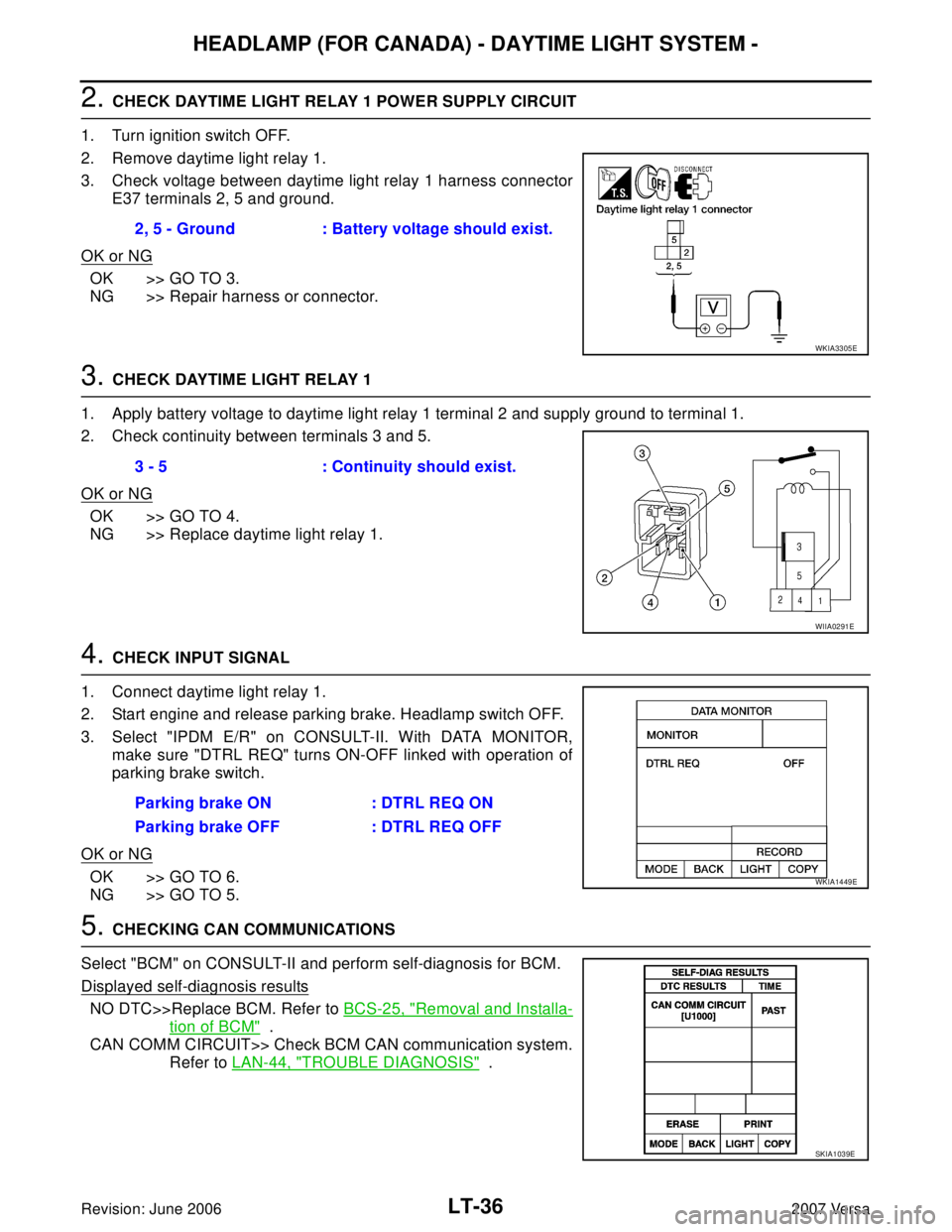
2. CHECK DAYTIME LIGHT RELAY 1 POWER SUPPLY CIRCUIT
1. Turn ignition switch OFF.
2. Remove daytime light relay 1.
3. Check voltage between daytime light relay 1 harness connector
E37 terminals 2, 5 and ground.
OK or NG
OK >> GO TO 3.
NG >> Repair harness or connector.
3. CHECK DAYTIME LIGHT RELAY 1
1. Apply battery voltage to daytime light relay 1 terminal 2 and supply ground to terminal 1.
2. Check continuity between terminals 3 and 5.
OK or NG
OK >> GO TO 4.
NG >> Replace daytime light relay 1.
4. CHECK INPUT SIGNAL
1. Connect daytime light relay 1.
2. Start engine and release parking brake. Headlamp switch OFF.
3. Select "IPDM E/R" on CONSULT-II. With DATA MONITOR,
make sure "DTRL REQ" turns ON-OFF linked with operation of
parking brake switch.
OK or NG
OK >> GO TO 6.
NG >> GO TO 5.
5. CHECKING CAN COMMUNICATIONS
Select "BCM" on CONSULT-II and perform self-diagnosis for BCM.
Displayed self-diagnosis results
NO DTC>>Replace BCM. Refer to BCS-25, "Removal and Installa-
tion of BCM" .
CAN COMM CIRCUIT>> Check BCM CAN communication system.
Refer to LAN-44, "
TROUBLE DIAGNOSIS" . 2, 5 - Ground : Battery voltage should exist.
WKIA3305E
3 - 5 : Continuity should exist.
WIIA0291E
Parking brake ON : DTRL REQ ON
Parking brake OFF : DTRL REQ OFF
WKIA1449E
SKIA1039E
Page 2245 of 2896

HEADLAMP (FOR CANADA) - DAYTIME LIGHT SYSTEM -
LT-37
C
D
E
F
G
H
I
J
L
MA
B
LT
Revision: June 20062007 Versa
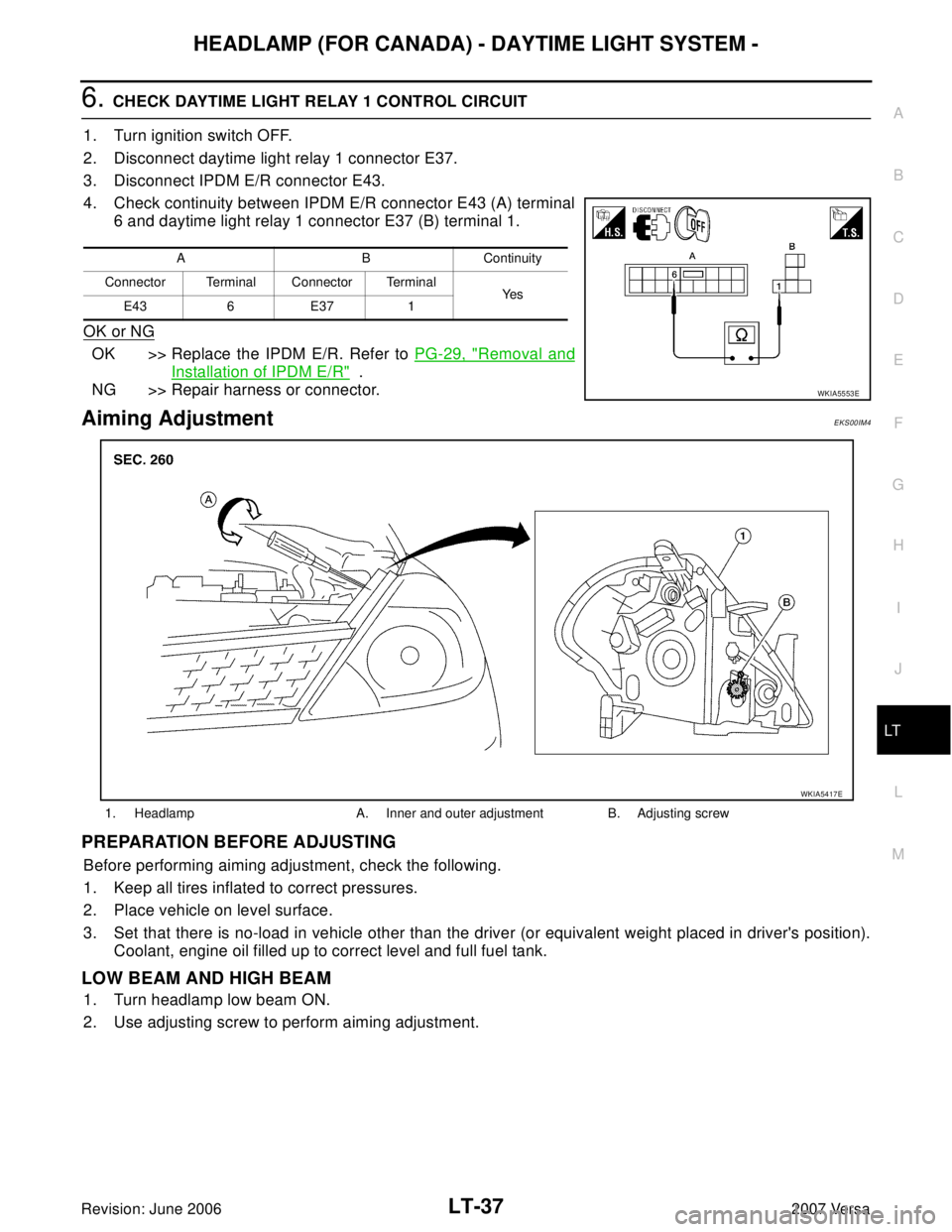
6. CHECK DAYTIME LIGHT RELAY 1 CONTROL CIRCUIT
1. Turn ignition switch OFF.
2. Disconnect daytime light relay 1 connector E37.
3. Disconnect IPDM E/R connector E43.
4. Check continuity between IPDM E/R connector E43 (A) terminal
6 and daytime light relay 1 connector E37 (B) terminal 1.
OK or NG
OK >> Replace the IPDM E/R. Refer to PG-29, "Removal and
Installation of IPDM E/R" .
NG >> Repair harness or connector.
Aiming AdjustmentEKS00IM4
PREPARATION BEFORE ADJUSTING
Before performing aiming adjustment, check the following.
1. Keep all tires inflated to correct pressures.
2. Place vehicle on level surface.
3. Set that there is no-load in vehicle other than the driver (or equivalent weight placed in driver's position).
Coolant, engine oil filled up to correct level and full fuel tank.
LOW BEAM AND HIGH BEAM
1. Turn headlamp low beam ON.
2. Use adjusting screw to perform aiming adjustment.
A B Continuity
Connector Terminal Connector Terminal
Ye s
E43 6 E37 1
WKIA5553E
1. Headlamp A. Inner and outer adjustment B. Adjusting screw
WKIA5417E
Page 2325 of 2896

LU-1
ENGINE LUBRICATION SYSTEM
B ENGINE
CONTENTS
C
D
E
F
G
H
I
J
K
L
M
SECTION LU
A
LU
Revision: June 20062007 Versa PRECAUTIONS .......................................................... 2
Precautions for Liquid Gasket .................................. 2
LIQUID GASKET APPLICATION PROCEDURE ..... 2
PREPARATION ........................................................... 3
Special Service Tools ............................................... 3
Commercial Service Tools ........................................ 3
LUBRICATION SYSTEM ............................................ 4
Lubrication Circuit .................................................... 4
ENGINE OIL ............................................................... 5
Inspection ................................................................. 5
ENGINE OIL LEVEL ............................................. 5
ENGINE OIL APPEARANCE ................................ 5ENGINE OIL LEAKAGE ........................................ 5
OIL PRESSURE CHECK ...................................... 5
Changing Engine Oil ................................................. 6
OIL FILTER ................................................................. 8
Removal and Installation .......................................... 8
REMOVAL ............................................................. 8
INSTALLATION ..................................................... 8
INSPECTION AFTER INSTALLATION .................. 8
SERVICE DATA AND SPECIFICATIONS (SDS) ........ 9
Standard and Limit .................................................... 9
OIL PRESSURE .................................................... 9
OIL CAPACITY ...................................................... 9