Page 2800 of 2896
![NISSAN VERSA 2006 Workshop Service Repair Manual STC-14
[EPS]
TROUBLE DIAGNOSIS
Revision: June 20062007 Versa
2. Turn ignition switch “OFF” to erase memory.
3. Turn ignition switch “ON” and select “SELF-DIAG RESULTS” mode with CONSULT-II](/manual-img/5/57401/w960_57401-2799.png "NISSAN VERSA 2006 Workshop Service Repair Manual STC-14
[EPS]
TROUBLE DIAGNOSIS
Revision: June 20062007 Versa
2. Turn ignition switch “OFF” to erase memory.
3. Turn ignition switch “ON” and select “SELF-DIAG RESULTS” mode with CONSULT-II")
STC-14
[EPS]
TROUBLE DIAGNOSIS
Revision: June 20062007 Versa
2. Turn ignition switch “OFF” to erase memory.
3. Turn ignition switch “ON” and select “SELF-DIAG RESULTS” mode with CONSULT-II.
4. Touch “ERASE” on CONSULT-II screen to erase DTC memory.
CAUTION:
If memory cannot be erased, perform diagnosis.
DATA MONITOR
Operation Procedure
1. Perform “CONSULT-II Start Procedure”. Refer to GI-38, "CONSULT-II Start Procedure" .
2. Touch “DATA MONITOR”.
3. Select from “SELECT MONITOR ITEM”, screen of data monitor mode is displayed.
NOTE:
When malfunction is detected, CONSULT-II performs REAL-TIME DIAGNOSIS. Also, any malfunc-
tion detected while in this mode will be displayed at real time.
Display Item List
EPS CONTROL UNIT PART NUMBER
Display a part number of EPS control unit carried by a vehicle.
Monitor item (Unit) Remarks
MOTOR VOL (V) Power supply voltage for EPS control unit is displayed
TORQUE SENSOR (Nm) Steering wheel turning force detected by torque sensor is displayed
MOTOR SIG (A) Current commanded value to EPS motor is displayed
MOTOR CURRENT (A) Current value consumed by EPS motor is displayed
VEHICLE SPEED (km/h) or (mph) Vehicle speed is displayed from vehicle speed signal with CAN communication
WARNING LAMP (ON/OFF) EPS warning lamp control status is displayed
DERATING STAT (ON/OFF) Protect overload status is displayed
ENGINE STATUS (STOP/RUN) Engine speed is displayed from engine status signal with CAN communication
SGIA1532E
Page 2801 of 2896
![NISSAN VERSA 2006 Workshop Service Repair Manual TROUBLE DIAGNOSIS
STC-15
[EPS]
C
D
E
F
H
I
J
K
L
MA
B
STC
Revision: June 20062007 Versa
Symptom ChartUGS0008I
If EPS warning lamp turns ON, perform self-diagnosis. Refer to STC-13, "SELF-DIAG RESULTS](/manual-img/5/57401/w960_57401-2800.png "NISSAN VERSA 2006 Workshop Service Repair Manual TROUBLE DIAGNOSIS
STC-15
[EPS]
C
D
E
F
H
I
J
K
L
MA
B
STC
Revision: June 20062007 Versa
Symptom ChartUGS0008I
If EPS warning lamp turns ON, perform self-diagnosis. Refer to STC-13, \"SELF-DIAG RESULTS")
TROUBLE DIAGNOSIS
STC-15
[EPS]
C
D
E
F
H
I
J
K
L
MA
B
STC
Revision: June 20062007 Versa
Symptom ChartUGS0008I
If EPS warning lamp turns ON, perform self-diagnosis. Refer to STC-13, "SELF-DIAG RESULTS MODE" .
Symptom Condition Check item Reference page
EPS warning lamp does not turn ON when
ignition switch to “ON”.
(EPS warning lamp check)Ignition switch: ONCAN communication line
STC-26
Combination meter
EPS warning lamp does not turn OFF for
several seconds after starting the engineEngine runningCAN communication line
STC-27
Power supply and ground for
EPS control unit
Torque sensor
EPS motor
Vehicle speed signal
Engine status signal
Combination meter
Steering wheel turning force is heavy or light,
while driving
�While driving
�Steering wheel turningCAN communication line
STC-29
Vehicle speed signal
Engine status signal
EPS motor
Steering wheel turning force
(Mechanical malfunction)
Unbalance steering wheel turning force and
return between right and left, while driving
�While driving
�Steering wheel turningWheel alignment
STC-31Steering wheel turning force
(Mechanical malfunction)
Unbalance steering wheel turning force,
while driving (Torque variation)
�While driving
�Steering wheel turningSteering column intermediate
shaft installation condition
STC-32Steering wheel turning force
(Mechanical malfunction)
Page 2805 of 2896
![NISSAN VERSA 2006 Workshop Service Repair Manual TROUBLE DIAGNOSIS FOR SYSTEM
STC-19
[EPS]
C
D
E
F
H
I
J
K
L
MA
B
STC
Revision: June 20062007 Versa
DTC C1604 TORQUE SENSORUGS0008K
CONSULT-II REFERENCE VALUE IN DATA MONITOR MODE
Data are reference va](/manual-img/5/57401/w960_57401-2804.png "NISSAN VERSA 2006 Workshop Service Repair Manual TROUBLE DIAGNOSIS FOR SYSTEM
STC-19
[EPS]
C
D
E
F
H
I
J
K
L
MA
B
STC
Revision: June 20062007 Versa
DTC C1604 TORQUE SENSORUGS0008K
CONSULT-II REFERENCE VALUE IN DATA MONITOR MODE
Data are reference va")
TROUBLE DIAGNOSIS FOR SYSTEM
STC-19
[EPS]
C
D
E
F
H
I
J
K
L
MA
B
STC
Revision: June 20062007 Versa
DTC C1604 TORQUE SENSORUGS0008K
CONSULT-II REFERENCE VALUE IN DATA MONITOR MODE
Data are reference value.
*: In the front of the value, “L” is displayed at steering left and “R” is displayed at steering right.
EPS CONTROL UNIT TERMINALS AND REFERENCE VALUE
Data are reference value and are measured between each terminal and ground.
CAUTION:
When using a circuit tester to measure voltage for inspection, be sure not to extend forcibly any connector terminals.
DIAGNOSTIC PROCEDURE
1. CHECK TORQUE SENSOR SIGNAL
With CONSULT-II
1. Start engine.
2. Select “DATA MONITOR” mode for “EPS” with CONSULT-II.
3. Check the value of “TORQUE SENSOR”. Refer to STC-11, "
SPECIFICATIONS WITH CONSULT-II" .
Without CONSULT-II
1. Start engine.
2. Check voltage between EPS control unit harness connector M53 terminals 4, 5, 6, 7 and ground. Refer to
STC-12, "
SPECIFICATIONS BETWEEN EPS CONTROL UNIT TERMINALS" .
OK or NG
OK >> GO TO 3.
NG >> GO TO 2.
Monitor item (Unit) Content Condition Display value
TORQUE SENSOR (Nm) Steering wheel turning force Engine runningSteering wheel: Not steering
(There is no steering force)0.00 Nm
Steering wheel: Steering0 – 8.19 Nm*
(The value is changed
according to steering
left or right)
TerminalWire
color Item Condition Data (Approx.)
4 V Torque sensor sub Engine runningSteering wheel: Not steering
(There is no steering force)2.5 V
Steering wheel: Steering1.7 V – 3.3 V
(The value is
changed accord-
ing to steering
left or right)
5 BR Torque sensor power supplyIgnition switch: ON 8 V
Ignition switch: OFF 0 V
6 G Torque sensor main Engine runningSteering wheel: Not steering
(There is no steering force)2.5 V
Steering wheel: Steering1.7 V – 3.3 V
(The value is
changed accord-
ing to steering
left or right)
7 R Torque sensor ground Always 0 V
Page 2818 of 2896
![NISSAN VERSA 2006 Workshop Service Repair Manual STC-32
[EPS]
TROUBLE DIAGNOSIS FOR SYMPTOMS
Revision: June 20062007 Versa
Unbalance Steering Wheel Turning Force (Torque Variation)UGS0008W
SYMPTOM:
Unbalance steering wheel turning force, while drivi](/manual-img/5/57401/w960_57401-2817.png "NISSAN VERSA 2006 Workshop Service Repair Manual STC-32
[EPS]
TROUBLE DIAGNOSIS FOR SYMPTOMS
Revision: June 20062007 Versa
Unbalance Steering Wheel Turning Force (Torque Variation)UGS0008W
SYMPTOM:
Unbalance steering wheel turning force, while drivi")
STC-32
[EPS]
TROUBLE DIAGNOSIS FOR SYMPTOMS
Revision: June 20062007 Versa
Unbalance Steering Wheel Turning Force (Torque Variation)UGS0008W
SYMPTOM:
Unbalance steering wheel turning force, while driving (Torque variation).
DIAGNOSTIC PROCEDURE
1. CHECK EPS WARNING LAMP
Confirm EPS warning lamp during engine running.
Does EPS warning lamp turn OFF?
YES >> GO TO 2.
NO >> Go to STC-27, "
EPS Warning Lamp Does Not Turn OFF" .
2. CHECK STEERING COLUMN INTERMEDIATE SHAFT
Check the connection between intermediate shaft and the mounting part of steering column assembly and
steering gear assembly. Refer to PS-9, "
COMPONENT" .
OK or NG
OK >> GO TO 3.
NG >> Repair or replace damaged parts.
3. CHECK EPS CONTROL UNIT
Check EPS control unit input/output signal. Refer to STC-11, "
EPS Control Unit Input/Output Signal Reference
Values" .
OK or NG
OK >> GO TO 4.
NG >> Check EPS control unit pin terminals for damage or loose connection with harness connector. If
any items are damaged, repair or replace damaged parts.
4. SYMPTOM CHECK
Check again.
OK or NG
OK >>INSPECTION END
NG >> Check the steering wheel turning force because there may be mechanical malfunction. Refer to
PS-6, "
CHECKING STEERING WHEEL TURNING FORCE" .
Page 2824 of 2896
WT-6
ROAD WHEEL TIRE ASSEMBLY
Revision: June 20062007 Versa
ROAD WHEEL TIRE ASSEMBLYPFP:40300
Balancing WheelsEES002D8
Adjust wheel balance using road wheel center.
CAUTION:
�Be careful not to scratch the road wheel during removal.
�Use clip-on type wheel balance weights only.
Wheel balance (Maximum allowable unbalance):
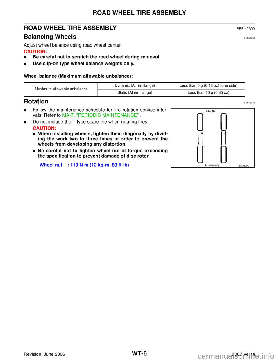
RotationEES002D9
�Follow the maintenance schedule for tire rotation service inter-
vals. Refer to MA-7, "
PERIODIC MAINTENANCE" .
�Do not include the T-type spare tire when rotating tires.
CAUTION:
�When installing wheels, tighten them diagonally by divid-
ing the work two to three times in order to prevent the
wheels from developing any distortion.
�Be careful not to tighten wheel nut at torque exceeding
the specification to prevent damage of disc rotor.
Maximum allowable unbalanceDynamic (At rim flange) Less than 5 g (0.18 oz) (one side)
Static (At rim flange) Less than 10 g (0.35 oz)
Wheel nut : 113 N·m (12 kg-m, 83 ft-lb)SM A82 9C