Page 2354 of 2896

MA-20
CHASSIS AND BODY MAINTENANCE
Revision: June 20062007 Versa
CHASSIS AND BODY MAINTENANCEPFP:00100
Changing In-cabin MicrofilterELS0022D
1. Remove the glove box assembly. Refer to IP-10, "INSTRUMENT PANEL ASSEMBLY" .
2. Compress the air conditioner filter (1) downward while sliding it
to the RH side of the vehicle to release the upper pawl.
3. Move the bottom of air conditioner filter (1) upward as shown to
release the bottom tab, then remove it.
4. Replace the air conditioner filter with new one and install the
new filter in the A/C unit assembly.
CAUTION:
Make sure that the air conditioner filter lower tab is fully
seated, and that the air conditioner upper pawl is locked
into place securing the new filter into the A/C unit assem-
bly.
Checking Exhaust SystemELS0021U
Check the exhaust pipes, muffler, and exhaust mounts for improper
attachment, leaks, cracks, damage, chafing, or deterioration.
Checking CVT FluidELS0021V
FLUID LEVEL CHECK
Fluid level should be checked with the fluid warmed up to 50 to 80°C (122 to 176°F).
1. Check for fluid leakage.
2. With the engine warmed up, drive the vehicle to warm up the
CVT fluid. When ambient temperature is 20°C (68°F), it takes
about 10 minutes for the CVT fluid to warm up to 50 to 80°C
(122 to 176°F).
3. Park the vehicle on a level surface and set the parking brake.
4. With engine at idle, while depressing brake pedal, move the
selector lever throughout the entire shift range and return it to
the “P” position.
5. Press the tab on the CVT fluid level gauge to release the lock
and pull out the CVT fluid level gauge from the CVT fluid charg-
ing pipe.
SJIA0652E
SM A211 A
SM A14 6B
SCIA1933E
Page 2483 of 2896
MODE DOOR
MTC-71
C
D
E
F
G
H
I
K
L
MA
B
MTC
Revision: June 20062007 Versa
MODE DOORPFP:27181
Mode Door Cable AdjustmentEJS00588
1. Remove glove box assembly and instrument lower cover (RH). Refer to IP-10, "INSTRUMENT PANEL
ASSEMBLY" .
2. Remove outer cable of mode door cable (1) from clamp (A).
3. Set mode control dial to VENT position.
4. Push main link (2) in the direction shown by the arrow, and then
carefully pull outer cable to controller side, and install clamp (A).
5. Operate mode control dial to insure that inner cable moves
smoothly.
CAUTION:
When clamping the outer cable, do not move the inner
cable.
6. Turn mode control dial to each position.
7. Confirm that discharge air comes out according to the air distribution table. Refer to MTC-22, "
Discharge
Air Flow" .
SJIA0654E
Page 2486 of 2896
 and the recirculated air (B) drawn inside the pa")
MTC-74
AIR CONDITIONER FILTER
Revision: June 20062007 Versa
AIR CONDITIONER FILTERPFP:27277
Removal and InstallationEJS0058B
FUNCTION
The fresh air (A) and the recirculated air (B) drawn inside the pas-
senger compartment by the blower fan (1) is kept clean (C) on either
mode by the air conditioner filter (2), located before the evaporator
(3), in the A/C unit assembly.
REPLACEMENT TIMING
Replace the air conditioner filter according to the maintenance schedules. Refer to MA-7, "PERIODIC MAIN-
TENANCE" .
NOTE:
The air conditioner filter caution label is located inside the glove box door.
REPLACEMENT PROCEDURES
1. Remove the glove box assembly. Refer to IP-10, "INSTRUMENT PANEL ASSEMBLY" .
2. Compress the air conditioner filter (1) downward while sliding it
to the RH side of the vehicle to release the upper pawl.
3. Move the bottom of air conditioner filter (1) upward as shown to
release the bottom tab, then remove it.
4. Replace the air conditioner filter with new one and install the new filter in the A/C unit assembly.
CAUTION:
Make sure that the air conditioner filter lower tab is fully seated, and that the air conditioner upper
pawl is locked into place securing the new filter into the A/C unit assembly.
5. Install the glove box assembly. Refer to IP-10, "
INSTRUMENT PANEL ASSEMBLY" .
WJIA2253E
SJIA0652E
Page 2558 of 2896
 E2")
PG-42
HARNESS
Revision: June 20062007 Versa
G1 M1 W/16 : To R1 G1 M47 BR/2 : Front tweeter RH
B3 M2 B/5 : Passenger select unlock relay B2 M48 L/4 : Heated mirror relay
B2 M3 W/1 : Fuse block (J/B) E2 M52 W/40 : Intelligent key unit
B3 M4 W/1 : Fuse block (J/B) B2 M53 W/16 : EPS control unit
B3 M5 W/3 : Illumination control switch B3 M54 B/2 : EPS control unit
C2 M6 W/4 : Steering lock solenoid C3 M55 W/4 : Hazard switch
B3 M7 W/16 : Door mirror remote control switch B2 M57 — : Body ground
A3 M8 W/16 : To D2 F2 M59 W/2 : Glove box lamp
A3 M9 W/16 : To D1 C1 M60 L/2 : EPS control unit
E2 M10 GR/2 : Instrument panel antenna F1 M61 — : Body ground
G3 M11 W/4 : To B106 E2 M62 W/2 : Front blower motor
G4 M12 W/16 : To B101 C1 M63 W/4 : Torque sensor
G3 M13 W/24 : To B102 A2 M69 SMJ : To E7
G3 M14 W/24 : To B120 G3 M74 W/12 : To D102
B4 M15 W/16 : To B23 G3 M75 W/12 : To D101
B4 M16 W/24 : To B24 F2 M77 Y/4 : Front passenger air bag module
D5 M17 B/1 : Parking brake switch A2 M78 B/2 : To E11
F2 M18 W/40 : BCM (body control module) B1 M79 — : Body ground
F2 M19 W/15 : BCM (body control module) D3 M150 W/4 : To M32
F3 M20 B/15 : BCM (body control module) C3 M151 W/4 : Front blower motor resistor
C2 M21 W/4 : NATS antenna amp.
B3 M22 W/16 : Data link connector
E3 M23 W/4 : Remote keyless entry receiver
C1 M24 W/40 : Combination meter
C3 M25 /2 : Diode-1
B2 M26 W/6 : Ignition switch
C2 M27 GR/6 : Key switch and key lock solenoid
C2 M28 W/16 : Combination switch
C3 M29 Y/6 : Combination switch (spiral cable)
C3 M30 GR/8 : Combination switch (spiral cable)
E3 M32 W/4 : To M150
D2 M33 B/15 : Front air control
D4 M35 Y/28 : Air bag diagnosis sensor unit
D2 M36 W/3 : Front passenger air bag OFF indicator
D4 M38 W/6 : A/T device
D4 M38 W/6 : CVT device (without intelligent key)
D4 M38 W/8 : CVT device (with intelligent key)
B3 M39 W/2 : Tire pressure warning check connector
D2 M41 W/2 : Defrost A/C switch
D3 M42 W/3 : Thermo control amp.
D2 M43 W/20 : Audio unit
D2 M44 W/16 : Audio unit
D2 M45 W/12 : Audio unit
A1 M46 BR/2 : Front tweeter LH
Page 2628 of 2896
RF-10
SUNROOF
Revision: June 20062007 Versa
SUNROOFPFP:91210
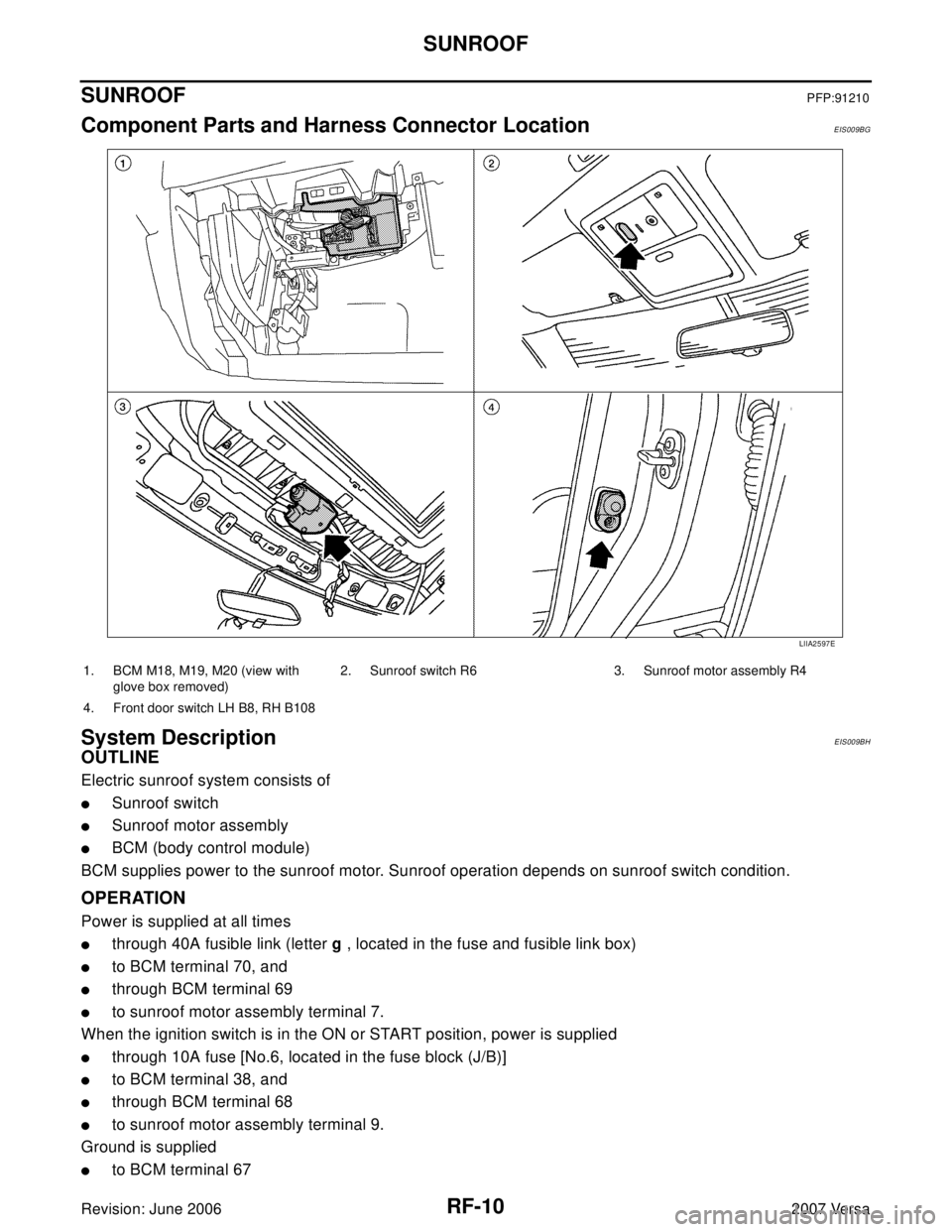
Component Parts and Harness Connector LocationEIS009BG
System DescriptionEIS009BH
OUTLINE
Electric sunroof system consists of
�Sunroof switch
�Sunroof motor assembly
�BCM (body control module)
BCM supplies power to the sunroof motor. Sunroof operation depends on sunroof switch condition.
OPERATION
Power is supplied at all times
�through 40A fusible link (letter g , located in the fuse and fusible link box)
�to BCM terminal 70, and
�through BCM terminal 69
�to sunroof motor assembly terminal 7.
When the ignition switch is in the ON or START position, power is supplied
�through 10A fuse [No.6, located in the fuse block (J/B)]
�to BCM terminal 38, and
�through BCM terminal 68
�to sunroof motor assembly terminal 9.
Ground is supplied
�to BCM terminal 67
LIIA2597E
1. BCM M18, M19, M20 (view with
glove box removed)2. Sunroof switch R6 3. Sunroof motor assembly R4
4. Front door switch LH B8, RH B108
Page 2825 of 2896
LOW TIRE PRESSURE WARNING SYSTEM
WT-7
C
D
F
G
H
I
J
K
L
MA
B
WT
Revision: June 20062007 Versa
LOW TIRE PRESSURE WARNING SYSTEMPFP:40300
System ComponentsEES002FF
System DescriptionEES002FG
BODY CONTROL MODULE (BCM)
The BCM is shown with the glove box removed. The BCM reads the
air pressure signal received by the remote keyless entry receiver,
and controls the low tire pressure warning lamp as shown below. It
also has a self-diagnosis function to detect a system malfunction.
WEIA0185E
1. BCM
M18, M202. Transmitters 3. Tire pressure warning check connector
M39
4. Combination meter
M245. Remote keyless entry receiver
M23
Condition Low tire pressure warning lamp
System normal On for 1 second after ignition ON
Tire less than 193 kPa (2.0 kg/cm
2 , 28 psi)
[Flat tire]ON
Low tire pressure warning system malfunc-
tionAfter key ON, flashes once per sec-
ond for 1 minute, then stays ON
WEIA0187E
Page 2826 of 2896
WT-8
LOW TIRE PRESSURE WARNING SYSTEM
Revision: June 20062007 Versa
TRANSMITTER
A sensor-transmitter integrated with a valve is installed in each
wheel, and transmits a detected air pressure signal in the form of a
radio wave. The radio signal is received by the remote keyless entry
receiver.
REMOTE KEYLESS ENTRY RECEIVER
The remote keyless entry receiver is shown with the glove box
removed. The remote keyless entry receiver receives the air pres-
sure signal transmitted by the transmitter in each wheel.
COMBINATION METER
The combination meter receives tire pressure status from the BCM
using CAN communication. When a low tire pressure condition is
sensed by the BCM, the combination meter low tire pressure warn-
ing lamp is activated.
WEIA0137E
WEIA0186E
LEIA0055E
Page 2852 of 2896

WW-4
FRONT WIPER AND WASHER SYSTEM
Revision: June 20062007 Versa
FRONT WIPER AND WASHER SYSTEMPFP:28810
Components Parts and Harness Connector LocationEKS00I1G
System DescriptionEKS00I1H
�Front wiper relays (front wiper relay, front wiper high relay) are located in the IPDM E/R (intelligent power
distribution module engine room).
�Wiper switch (combination switch) is composed of a combination of 5 output terminals and 5 input termi-
nals. Terminal combination status is read by BCM (body control module) when switch is turned ON.
�BCM controls front wiper LO, HI, and INT (intermittent) operation.
�IPDM E/R operates wiper motor according to CAN communication signals from BCM.
OUTLINE
Power is supplied at all times
�to ignition relay, located in IPDM E/R, from battery directly,
�through 40A fusible link (letter g, located in fuse, fusible link and relay box)
�to BCM terminal 70,
�through 30A fuse (No. 39, located in IPDM E/R)
�to front wiper relay located in IPDM E/R
�through 15A fuse (No. 52, located in IPDM E/R), and
�through 20A fuse (No. 53, located in IPDM E/R)
�to CPU located in IPDM E/R.
When ignition switch is in ON or START position, power is supplied
�through ignition relay (located in IPDM E/R)
1. IPDM E/R E45, E46 and E48 2. BCM M18 and M20 (view with glove
box removed)3. Front wiper motor E1 (View with
cowl top cover removed)
4. Front and rear washer motor E2
(View with front fender protector LH
removed)5. Combination switch (wiper switch)
M28
WKIA5467E
. Refer to I")