Page 2518 of 2896
 .................................................................. 68
HARNESS CONNECTOR (SLIDE-LOCKING
TYPE) ..................................................")
PG-2Revision: June 20062007 Versa TYPE) .................................................................. 68
HARNESS CONNECTOR (SLIDE-LOCKING
TYPE) .................................................................. 69
HARNESS CONNECTOR (LEVER LOCKING
TYPE) .................................................................. 70
HARNESS CONNECTOR (DIRECT-CONNECT
SRS COMPONENT TYPE) ................................. 71
ELECTRICAL UNITS ................................................ 72
Terminal Arrangement ............................................ 72STANDARDIZED RELAY ..........................................73
Description ..............................................................73
NORMAL OPEN, NORMAL CLOSED AND
MIXED TYPE RELAYS ........................................73
TYPE OF STANDARDIZED RELAYS ..................73
SUPER MULTIPLE JUNCTION (SMJ) ......................75
Terminal Arrangement .............................................75
FUSE BLOCK-JUNCTION BOX (J/B) ......................76
Terminal Arrangement .............................................76
FUSE AND FUSIBLE LINK BOX ..............................77
Terminal Arrangement .............................................77
Page 2533 of 2896

PG-17
C
D
E
F
G
H
I
J
L
MA
B
PG
Revision: June 20062007 Versa
IPDM E/R (INTELLIGENT POWER DISTRIBUTION MODULE ENGINE ROOM)
PFP:284B7
System")
IPDM E/R (INTELLIGENT POWER DISTRIBUTION MODULE ENGINE ROOM)
PG-17
C
D
E
F
G
H
I
J
L
MA
B
PG
Revision: June 20062007 Versa
IPDM E/R (INTELLIGENT POWER DISTRIBUTION MODULE ENGINE ROOM)
PFP:284B7
System DescriptionEKS00JLJ
�IPDM E/R (Intelligent Power Distribution Module Engine Room) integrates the relay box and fuse block
which were originally placed in engine compartment. It controls integrated relays via IPDM E/R control cir-
cuits.
�IPDM E/R-integrated control circuits perform ON-OFF operation of relays, CAN communication control, oil
pressure switch signal reception, etc.
�It controls operation of each electrical component via ECM, BCM and CAN communication lines.
CAUTION:
None of the IPDM E/R integrated relays can be removed.
SYSTEMS CONTROLLED BY IPDM E/R
1. Lamp control
Using CAN communication lines, it receives signals from the BCM and controls the following lamps:
�Headlamps (High, Low)
�Parking lamps
�Tail and license plate lamps
�Front fog lamps
2. Wiper control
Using CAN communication lines, it receives signals from the BCM and controls the front wipers.
3. Rear window defogger relay control
Using CAN communication lines, it receives signals from the BCM and controls the rear window defogger
relay.
4. A/C compressor control
Using CAN communication lines, it receives signals from the ECM and controls the A/C compressor
(magnet clutch).
5. Starter control
Using CAN communication lines, it receives signals from the BCM and controls the starter relay.
6. Cooling fan control
Using CAN communication lines, it receives signals from the ECM and controls the cooling fan relays.
7. Horn control
Using CAN communication lines, it receives signals from the BCM and controls the horn relay.
8. Daytime light system control (Canada only)
Using CAN communication lines, it receives signals from the BCM and controls the daytime light relay.
CAN COMMUNICATION LINE CONTROL
With CAN communication, by connecting each control unit using two communication lines (CAN L-line, CAN
H-line), it is possible to transmit a maximum amount of information with minimum wiring. Each control unit can
transmit and receive data, and reads necessary information only.
1. Fail-safe control
�When CAN communication with other control units is impossible, IPDM E/R performs fail-safe control.
After CAN communication returns to normal operation, it also returns to normal control.
�Operation of control parts by IPDM E/R during fail-safe mode is as follows:
Controlled system Fail-safe mode
Headlamp
�With the ignition switch ON, headlamp low relay is ON, headlamp high relays are OFF,
and daytime light system (Canada only) is OFF.
�With the ignition switch OFF, the headlamp relays are OFF.
Tail, license plate and parking lamps
�With the ignition switch ON, the tail lamp relay is ON.
�With the ignition switch OFF, the tail lamp relay is OFF.
Cooling fan
�With the ignition switch ON, cooling fan relay-1, relay-2, and relay-3 are ON.
�With the ignition switch OFF, all cooling fan relays are OFF.
Front wiperUntil the ignition switch is turned off, the front wiper relays remain in the same status they
were in just before fail−safe control was initiated.
Page 2558 of 2896
 E2")
PG-42
HARNESS
Revision: June 20062007 Versa
G1 M1 W/16 : To R1 G1 M47 BR/2 : Front tweeter RH
B3 M2 B/5 : Passenger select unlock relay B2 M48 L/4 : Heated mirror relay
B2 M3 W/1 : Fuse block (J/B) E2 M52 W/40 : Intelligent key unit
B3 M4 W/1 : Fuse block (J/B) B2 M53 W/16 : EPS control unit
B3 M5 W/3 : Illumination control switch B3 M54 B/2 : EPS control unit
C2 M6 W/4 : Steering lock solenoid C3 M55 W/4 : Hazard switch
B3 M7 W/16 : Door mirror remote control switch B2 M57 — : Body ground
A3 M8 W/16 : To D2 F2 M59 W/2 : Glove box lamp
A3 M9 W/16 : To D1 C1 M60 L/2 : EPS control unit
E2 M10 GR/2 : Instrument panel antenna F1 M61 — : Body ground
G3 M11 W/4 : To B106 E2 M62 W/2 : Front blower motor
G4 M12 W/16 : To B101 C1 M63 W/4 : Torque sensor
G3 M13 W/24 : To B102 A2 M69 SMJ : To E7
G3 M14 W/24 : To B120 G3 M74 W/12 : To D102
B4 M15 W/16 : To B23 G3 M75 W/12 : To D101
B4 M16 W/24 : To B24 F2 M77 Y/4 : Front passenger air bag module
D5 M17 B/1 : Parking brake switch A2 M78 B/2 : To E11
F2 M18 W/40 : BCM (body control module) B1 M79 — : Body ground
F2 M19 W/15 : BCM (body control module) D3 M150 W/4 : To M32
F3 M20 B/15 : BCM (body control module) C3 M151 W/4 : Front blower motor resistor
C2 M21 W/4 : NATS antenna amp.
B3 M22 W/16 : Data link connector
E3 M23 W/4 : Remote keyless entry receiver
C1 M24 W/40 : Combination meter
C3 M25 /2 : Diode-1
B2 M26 W/6 : Ignition switch
C2 M27 GR/6 : Key switch and key lock solenoid
C2 M28 W/16 : Combination switch
C3 M29 Y/6 : Combination switch (spiral cable)
C3 M30 GR/8 : Combination switch (spiral cable)
E3 M32 W/4 : To M150
D2 M33 B/15 : Front air control
D4 M35 Y/28 : Air bag diagnosis sensor unit
D2 M36 W/3 : Front passenger air bag OFF indicator
D4 M38 W/6 : A/T device
D4 M38 W/6 : CVT device (without intelligent key)
D4 M38 W/8 : CVT device (with intelligent key)
B3 M39 W/2 : Tire pressure warning check connector
D2 M41 W/2 : Defrost A/C switch
D3 M42 W/3 : Thermo control amp.
D2 M43 W/20 : Audio unit
D2 M44 W/16 : Audio unit
D2 M45 W/12 : Audio unit
A1 M46 BR/2 : Front tweeter LH
Page 2560 of 2896
 C3 E47 BR/8: IPDM E/R (Intelligent Power Distribu-
tion Module Engine Room)
C4 E3 B/2 : Cooling fan motor (wi")
PG-44
HARNESS
Revision: June 20062007 Versa
C4 E3 GR/4 : Cooling fan motor (without A/C) C3 E47 BR/8: IPDM E/R (Intelligent Power Distribu-
tion Module Engine Room)
C4 E3 B/2 : Cooling fan motor (with A/C) D3 E48 B/6: IPDM E/R (Intelligent Power Distribu-
tion Module Engine Room)
C4 E5 GR/3 : Resistor D1 E51 B/2 : Front wheel sensor LH
C3 E6 — : Fuse and fusible link box D3 E53 B/2: Front combination lamp LH
(parking)
B1 E7 SMJ : To M69
D3 E8 SMJ : To F8
B4 E9 BR/2 : Fusible link box (battery)
B3 E10 GR/2 : Fusible link box (battery)
B1 E11 B/2 : To M78
A3 E12 B/6 : Accelerator pedal position sensor
A2 E13 B/2 : Stop lamp switch (with M/T)
A2 E13 W/4 : Stop lamp switch (without M/T)
D3 E14 — : Engine ground (crash zone sensor)
C2 E15 — : Engine ground
B2 E16 B/32 : ECM
C5 E18 B/1 : Horn (low)
C4 E19 GR/6 : To F33
D5 E20 B/1 : Horn (low)
D3 E25 B/3: Front combination lamp LH
(headlamp)
E4 E27 B/2 : Front fog lamp LH
D4 E29 B/2: Front combination lamp LH
(turn signal)
B1 E31 W/24 : TCM
B1 E32 GR/24 : TCM
A2 E34 BR/2 : Clutch interlock switch (with M/T)
A2 E35 BR/2 : ASCD clutch switch
A2 E36 BR/2 : ASCD brake switch
B4 E40 GR/2 : Brake fluid level switch
D3 E42 B/2: IPDM E/R (Intelligent Power Distribu-
tion Module Engine Room)
C3 E43 W/16: IPDM E/R (Intelligent Power Distribu-
tion Module Engine Room)
C3 E44 W/6: IPDM E/R (Intelligent Power Distribu-
tion Module Engine Room)
D3 E45 BR/12: IPDM E/R (Intelligent Power Distribu-
tion Module Engine Room)
D3 E46 W/12: IPDM E/R (Intelligent Power Distribu-
tion Module Engine Room)
Page 2592 of 2896
PG-76
FUSE BLOCK-JUNCTION BOX (J/B)
Revision: June 20062007 Versa
FUSE BLOCK-JUNCTION BOX (J/B)PFP:24010
Terminal ArrangementEKS00I64
LKIA0812E
Page 2593 of 2896
FUSE AND FUSIBLE LINK BOX
PG-77
C
D
E
F
G
H
I
J
L
MA
B
PG
Revision: June 20062007 Versa
FUSE AND FUSIBLE LINK BOXPFP:24382
Terminal ArrangementEKS00I65
WKIA5604E
Page 2594 of 2896
PG-78
FUSE AND FUSIBLE LINK BOX
Revision: June 20062007 Versa
Page 2628 of 2896
RF-10
SUNROOF
Revision: June 20062007 Versa
SUNROOFPFP:91210
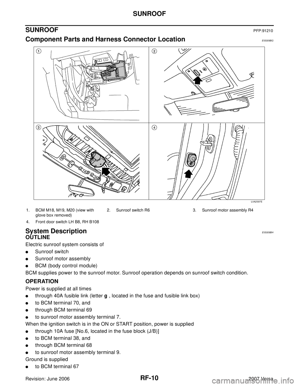
Component Parts and Harness Connector LocationEIS009BG
System DescriptionEIS009BH
OUTLINE
Electric sunroof system consists of
�Sunroof switch
�Sunroof motor assembly
�BCM (body control module)
BCM supplies power to the sunroof motor. Sunroof operation depends on sunroof switch condition.
OPERATION
Power is supplied at all times
�through 40A fusible link (letter g , located in the fuse and fusible link box)
�to BCM terminal 70, and
�through BCM terminal 69
�to sunroof motor assembly terminal 7.
When the ignition switch is in the ON or START position, power is supplied
�through 10A fuse [No.6, located in the fuse block (J/B)]
�to BCM terminal 38, and
�through BCM terminal 68
�to sunroof motor assembly terminal 9.
Ground is supplied
�to BCM terminal 67
LIIA2597E
1. BCM M18, M19, M20 (view with
glove box removed)2. Sunroof switch R6 3. Sunroof motor assembly R4
4. Front door switch LH B8, RH B108

Revision: June 20062007 Versa
FUSE BLOCK-JUNCTION BOX (J/B)PFP:24010
Terminal ArrangementEKS00I64
LKIA0812E")