Page 2271 of 2896
TURN SIGNAL AND HAZARD WARNING LAMPS
LT-63
C
D
E
F
G
H
I
J
L
MA
B
LT
Revision: June 20062007 Versa
3. CHECK GROUND CIRCUIT
Check continuity between hazard switch harness connector M55 ter-
minal 1 and ground.
OK or NG
OK >> GO TO 4.
NG >> Repair harness or connector.
4. CHECK HAZARD SWITCH
1. Disconnect hazard switch connector.
2. Check continuity hazard switch terminals.
OK or NG
OK >> Replace BCM if hazard warning lamps do not operate
after setting the connector again. Refer to BCS-25,
"Removal and Installation of BCM" .
NG >> Replace hazard switch.
Turn Signal Indicator Lamp Does Not OperateEKS00J8H
1. CHECK CAN COMMUNICATION SYSTEM
Check CAN communication. Refer to LAN-44, "
TROUBLE DIAGNOSIS" .
OK or NG
OK >> Replace combination meter. Refer to DI-23, "Removal and Installation" .
NG >> Repair as necessary.1 – Ground : Continuity should exist.
PKIC1016E
Te r m i n a l
Condition Continuity
Hazard switch
12Hazard switch is ON Yes
Hazard switch is OFF No
PKIC1017E
Page 2272 of 2896
LT-64
TURN SIGNAL AND HAZARD WARNING LAMPS
Revision: June 20062007 Versa
Bulb Replacement of Front Turn Signal LampEKS00HYB
Refer to LT- 2 5 , "Bulb Replacement" .
Bulb Replacement of Rear Turn Signal LampEKS00HYC
Refer to LT- 8 7 , "Bulb Replacement" .
Removal and Installation of Front Turn Signal LampEKS00HYE
Refer to LT- 2 5 , "Removal and Installation" .
Removal and Installation of Rear Turn Signal Lamp EKS00HYF
Refer to LT- 8 7 , "Removal and Installation" .
Page 2273 of 2896
LIGHTING AND TURN SIGNAL SWITCH
LT-65
C
D
E
F
G
H
I
J
L
MA
B
LT
Revision: June 20062007 Versa
LIGHTING AND TURN SIGNAL SWITCHPFP:25540
Removal and InstallationEKS00HYH
REMOVAL
1. Remove steering column cover. Refer to IP-10, "INSTRUMENT PANEL ASSEMBLY" .
2. While pressing pawls (A) in direction as shown, pull lighting and
turn signal switch (1) toward LH door and disconnect from the
base.
INSTALLATION
Installation is in the reverse order of removal.
PKIC1018E
Page 2276 of 2896
LT-68
COMBINATION SWITCH
Revision: June 20062007 Versa
Combination Switch Reading FunctionEKS00HYK
For details, refer to BCS-3, "COMBINATION SWITCH READING FUNCTION" .
Terminals and Reference Values for BCMEKS00HYL
Refer to BCS-12, "Terminals and Reference Values for BCM" .
CONSULT-II Function (BCM)EKS00HYN
Refer to LT- 1 2 , "CONSULT-II Function (BCM)" .
Combination Switch InspectionEKS00HYO
1. SYSTEM CHECK
Referring to table below, check which system malfunctioning switch belongs to.
>> Check the system to which the switch belongs, and GO TO 2.
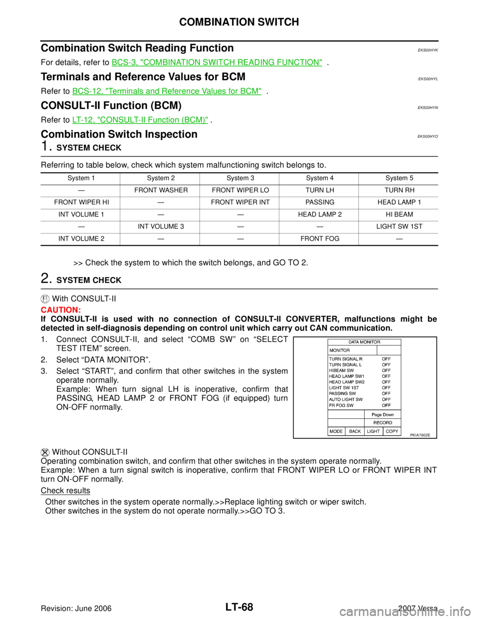
2. SYSTEM CHECK
With CONSULT-II
CAUTION:
If CONSULT-II is used with no connection of CONSULT-II CONVERTER, malfunctions might be
detected in self-diagnosis depending on control unit which carry out CAN communication.
1. Connect CONSULT-II, and select “COMB SW” on “SELECT
TEST ITEM” screen.
2. Select “DATA MONITOR”.
3. Select “START”, and confirm that other switches in the system
operate normally.
Example: When turn signal LH is inoperative, confirm that
PASSING, HEAD LAMP 2 or FRONT FOG (if equipped) turn
ON-OFF normally.
Without CONSULT-II
Operating combination switch, and confirm that other switches in the system operate normally.
Example: When a turn signal switch is inoperative, confirm that FRONT WIPER LO or FRONT WIPER INT
turn ON-OFF normally.
Check results
Other switches in the system operate normally.>>Replace lighting switch or wiper switch.
Other switches in the system do not operate normally.>>GO TO 3.
System 1 System 2 System 3 System 4 System 5
— FRONT WASHER FRONT WIPER LO TURN LH TURN RH
FRONT WIPER HI — FRONT WIPER INT PASSING HEAD LAMP 1
INT VOLUME 1 — — HEAD LAMP 2 HI BEAM
— INT VOLUME 3 — — LIGHT SW 1ST
INT VOLUME 2 — — FRONT FOG —
PKIA7602E
Page 2278 of 2896
LT-70
COMBINATION SWITCH
Revision: June 20062007 Versa
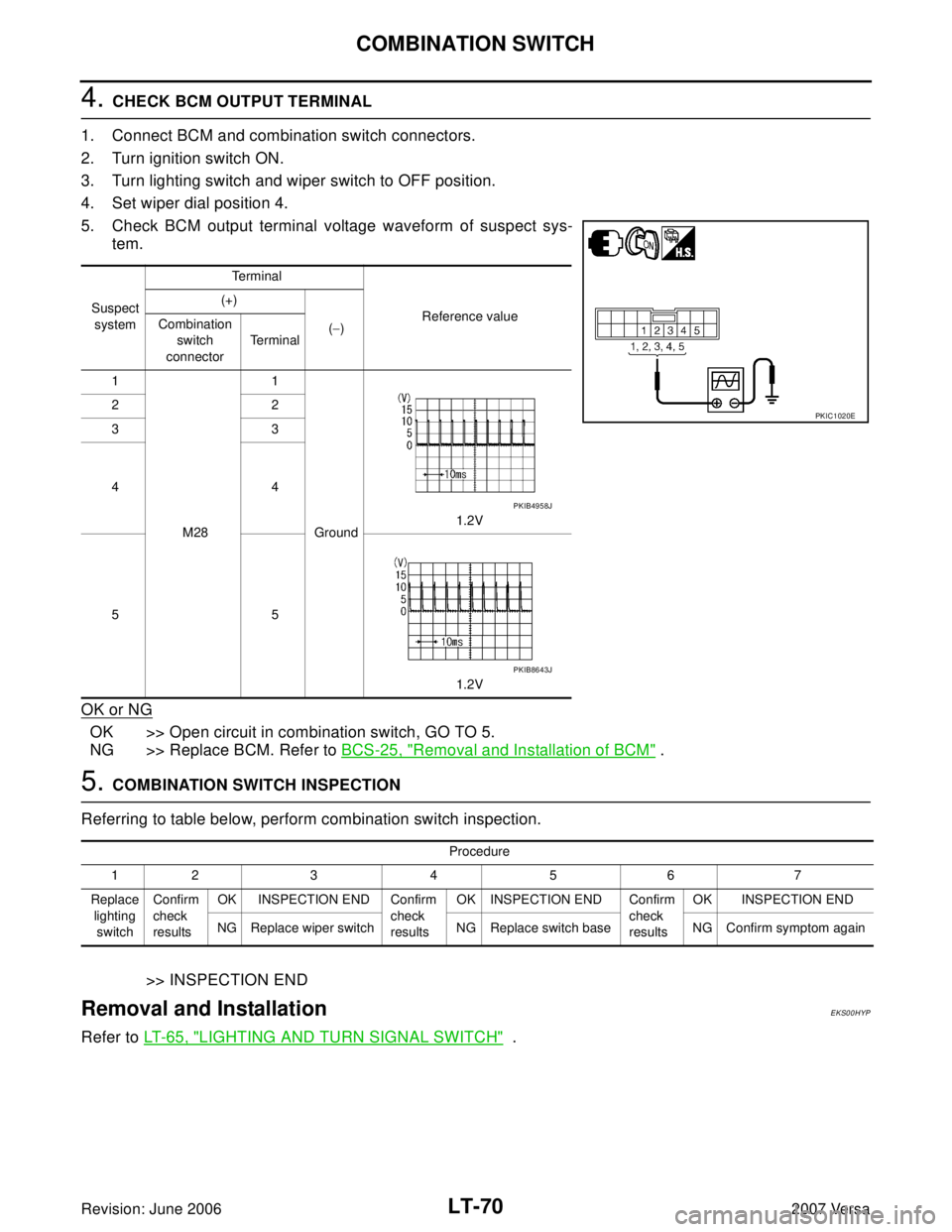
4. CHECK BCM OUTPUT TERMINAL
1. Connect BCM and combination switch connectors.
2. Turn ignition switch ON.
3. Turn lighting switch and wiper switch to OFF position.
4. Set wiper dial position 4.
5. Check BCM output terminal voltage waveform of suspect sys-
tem.
OK or NG
OK >> Open circuit in combination switch, GO TO 5.
NG >> Replace BCM. Refer to BCS-25, "
Removal and Installation of BCM" .
5. COMBINATION SWITCH INSPECTION
Referring to table below, perform combination switch inspection.
>> INSPECTION END
Removal and InstallationEKS00HYP
Refer to LT- 6 5 , "LIGHTING AND TURN SIGNAL SWITCH" .
Suspect
systemTe r m i n a l
Reference value (+)
(−) Combination
switch
connectorTe r m i n a l
1
M281
Ground1.2V 22
33
44
55
1.2V
PKIC1020E
PKIB4958J
PKIB8643J
Procedure
12 3 4 5 6 7
Replace
lighting
switchConfirm
check
resultsOK INSPECTION END Confirm
check
resultsOK INSPECTION END Confirm
check
resultsOK INSPECTION END
NG Replace wiper switch NG Replace switch base NG Confirm symptom again
Page 2289 of 2896
PARKING, LICENSE PLATE AND TAIL LAMPS
LT-81
C
D
E
F
G
H
I
J
L
MA
B
LT
Revision: June 20062007 Versa
Terminals and Reference Values for BCMEKS00HZ4
Refer to BCS-12, "Terminals and Reference Values for BCM" .
Terminals and Reference Values for IPDM E/REKS00HZ5
Refer to PG-25, "Terminals and Reference Values for IPDM E/R" .
How to Proceed With Trouble DiagnosisEKS00HZ6
1. Confirm the symptom or customer complaint.
2. Understand operation description and function description. Refer to LT- 7 5 , "
System Description" .
3. Perform the preliminary check. Refer to LT-81, "
Preliminary Check" .
4. Check symptom and repair or replace the component.
5. Do the parking, license plate and tail lamps operate normally? If YES, GO TO 6. If NO, GO TO 4.
6. Inspection End.
Preliminary CheckEKS00HZ7
CHECK POWER SUPPLY AND GROUND CIRCUIT FOR BCM
Refer to BCS-16, "BCM Power Supply and Ground Circuit Check" .
CHECK POWER SUPPLY AND GROUND CIRCUIT FOR IPDM E/R
Refer to PG-28, "IPDM E/R Power/Ground Circuit Inspection" .
CONSULT-II Function (BCM)EKS00HZ8
Refer to LT- 1 2 , "CONSULT-II Function (BCM)" .
CONSULT-II Function (IPDM E/R)EKS00HZ9
Refer to LT- 1 3 , "CONSULT-II Function (IPDM E/R)" .
Parking, License Plate and Tail Lamps Do Not IlluminateEKS00HZA
1. CHECK TAIL LAMP FUSE
Inspect tail lamp 10A fuse (No. 37, located in IPDM E/R).
OK or NG
OK >> GO TO 2.
NG >> Repair harness.
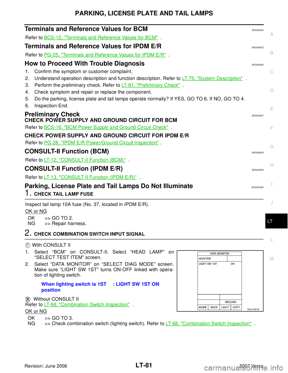
2. CHECK COMBINATION SWITCH INPUT SIGNAL
With CONSULT II
1. Select “BCM” on CONSULT-II. Select “HEAD LAMP” on
“SELECT TEST ITEM” screen.
2. Select “DATA MONITOR” on “SELECT DIAG MODE” screen.
Make sure “LIGHT SW 1ST” turns ON-OFF linked with opera-
tion of lighting switch.
Without CONSULT II
Refer to LT- 6 8 , "
Combination Switch Inspection" .
OK or NG
OK >> GO TO 3.
NG >> Check combination switch (lighting switch). Refer to LT-68, "
Combination Switch Inspection" . When lighting switch is 1ST
position: LIGHT SW 1ST ON
PKIA7607E
Page 2291 of 2896
PARKING, LICENSE PLATE AND TAIL LAMPS
LT-83
C
D
E
F
G
H
I
J
L
MA
B
LT
Revision: June 20062007 Versa
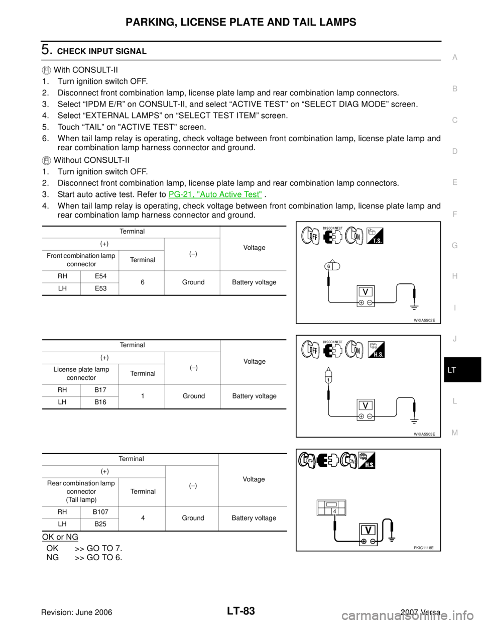
5. CHECK INPUT SIGNAL
With CONSULT-II
1. Turn ignition switch OFF.
2. Disconnect front combination lamp, license plate lamp and rear combination lamp connectors.
3. Select “IPDM E/R” on CONSULT-II, and select “ACTIVE TEST” on “SELECT DIAG MODE” screen.
4. Select “EXTERNAL LAMPS” on “SELECT TEST ITEM” screen.
5. Touch “TAIL” on "ACTIVE TEST" screen.
6. When tail lamp relay is operating, check voltage between front combination lamp, license plate lamp and
rear combination lamp harness connector and ground.
Without CONSULT-II
1. Turn ignition switch OFF.
2. Disconnect front combination lamp, license plate lamp and rear combination lamp connectors.
3. Start auto active test. Refer to PG-21, "
Auto Active Test" .
4. When tail lamp relay is operating, check voltage between front combination lamp, license plate lamp and
rear combination lamp harness connector and ground.
OK or NG
OK >> GO TO 7.
NG >> GO TO 6.
Te r m i n a l
Voltage (+)
(−)
Front combination lamp
connectorTe r m i n a l
RH E54
6 Ground Battery voltage
LH E53
WKIA5502E
Te r m i n a l
Voltage (+)
(−)
License plate lamp
connectorTe r m i n a l
RH B17
1 Ground Battery voltage
LH B16
WKIA5503E
Terminal
Voltag e (+)
(−) Rear combination lamp
connector
(Tail lamp)Te r m i n a l
RH B107
4 Ground Battery voltage
LH B25
PK I C 111 8E
Page 2295 of 2896
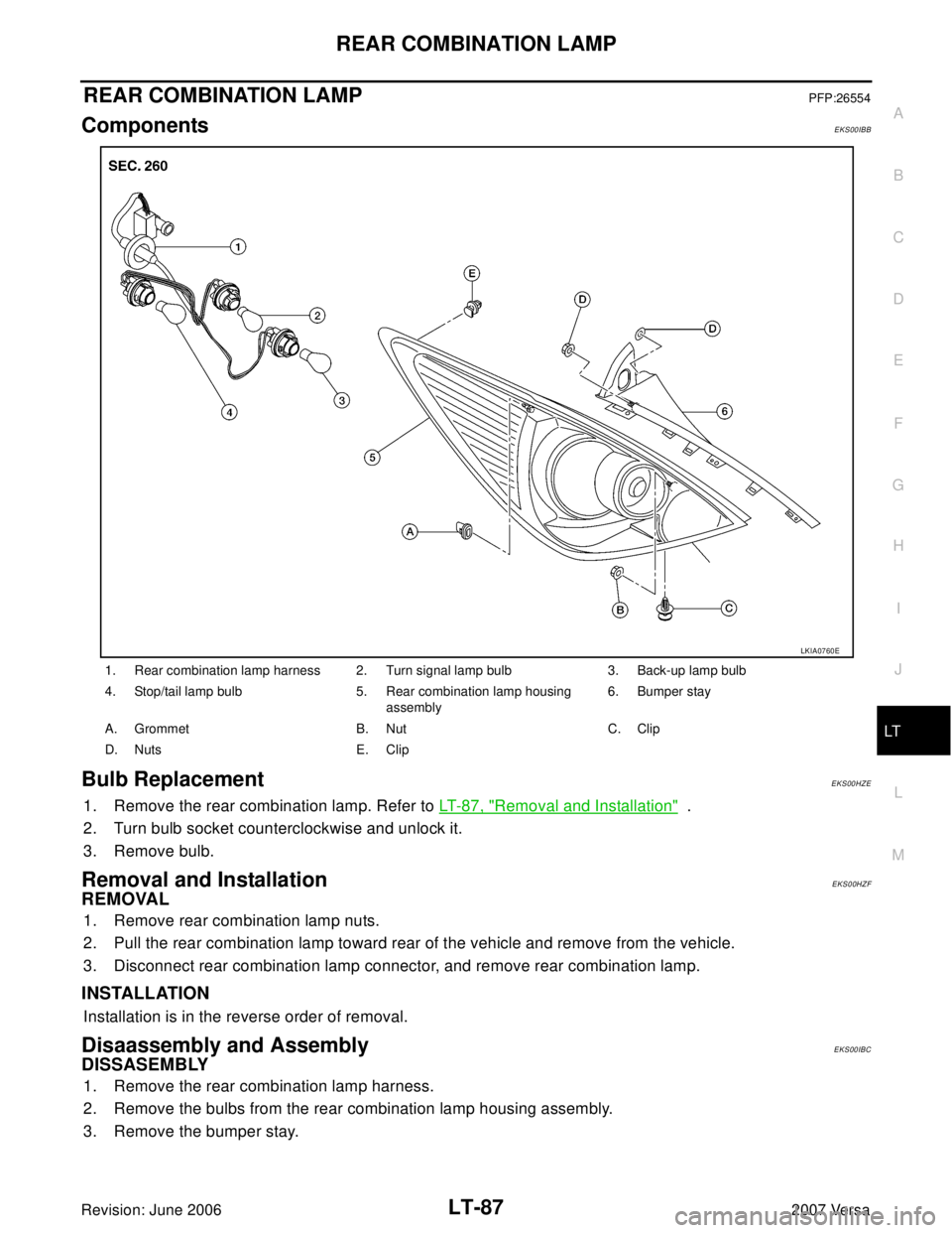
REAR COMBINATION LAMP
LT-87
C
D
E
F
G
H
I
J
L
MA
B
LT
Revision: June 20062007 Versa
REAR COMBINATION LAMPPFP:26554
ComponentsEKS00IBB
Bulb ReplacementEKS00HZE
1. Remove the rear combination lamp. Refer to LT- 8 7 , "Removal and Installation" .
2. Turn bulb socket counterclockwise and unlock it.
3. Remove bulb.
Removal and InstallationEKS00HZF
REMOVAL
1. Remove rear combination lamp nuts.
2. Pull the rear combination lamp toward rear of the vehicle and remove from the vehicle.
3. Disconnect rear combination lamp connector, and remove rear combination lamp.
INSTALLATION
Installation is in the reverse order of removal.
Disaassembly and AssemblyEKS00IBC
DISSASEMBLY
1. Remove the rear combination lamp harness.
2. Remove the bulbs from the rear combination lamp housing assembly.
3. Remove the bumper stay.
1. Rear combination lamp harness 2. Turn signal lamp bulb 3. Back-up lamp bulb
4. Stop/tail lamp bulb 5. Rear combination lamp housing
assembly6. Bumper stay
A. Grommet B. Nut C. Clip
D. Nuts E. Clip
LKIA0760E