2006 NISSAN VERSA air condition
[x] Cancel search: air conditionPage 2176 of 2896
![NISSAN VERSA 2006 Workshop Service Repair Manual LAN-50
[CAN]
TROUBLE DIAGNOSIS
Revision: June 20062007 Versa
*1: Models with ABS
*2: Models with air conditioner
*3: Models for Canada
*4: Models for USA
NOTE:
CAN data of the air bag diagnosis sensor NISSAN VERSA 2006 Workshop Service Repair Manual LAN-50
[CAN]
TROUBLE DIAGNOSIS
Revision: June 20062007 Versa
*1: Models with ABS
*2: Models with air conditioner
*3: Models for Canada
*4: Models for USA
NOTE:
CAN data of the air bag diagnosis sensor](/manual-img/5/57401/w960_57401-2175.png)
LAN-50
[CAN]
TROUBLE DIAGNOSIS
Revision: June 20062007 Versa
*1: Models with ABS
*2: Models with air conditioner
*3: Models for Canada
*4: Models for USA
NOTE:
CAN data of the air bag diagnosis sensor unit is not used by usual service work, thus it is omitted.
TYPE 7/TYPE 8/TYPE 9/TYPE 10
NOTE:
Refer to LAN-41, "
Abbreviation List" for the abbreviations of the connecting units.
T: Transmit R: Receive Low beam request signal T R
Position lights request signal T R R
Rear window defogger switch signal T R
Theft warning horn request signal T R
Tire pressure signal
*4TR
Turn indicator signal T R
EPS operation signal R T
EPS warning lamp signal T R
Fuel level sensor signal R T
Overdrive control switch signal T R
P/N range signal T R
Sleep/wake up signalRT
TR R
Stop lamp switch signal T R
Vehicle speed signalRRR T
RRRT
ABS warning lamp signal R T
Brake warning lamp signal R T
A/T check indicator signal R T
A/T self-diagnosis signal R T
OD OFF indicator signal R T
Output shaft revolution signal R T
Shift position signal R T
Turbine revolution signal R T
Front wiper stop position signal R T
High beam status signal RT
Low beam status signal RT
Oil pressure switch signal R T
Rear window defogger control signal RT Signals ECM BCM EPS M&A
ABS
*1TCM IPDM-E
Signals ECM BCM EPS
I-KEY*1M&A
ABS*2TCM IPDM-E
A/C compressor request signal TR
Accelerator pedal position signal T R
ASCD CRUISE lamp signal T R
ASCD SET lamp signal T R
Closed throttle position signal T R
Page 2226 of 2896
LT-18
HEADLAMP (FOR USA)
Revision: June 20062007 Versa
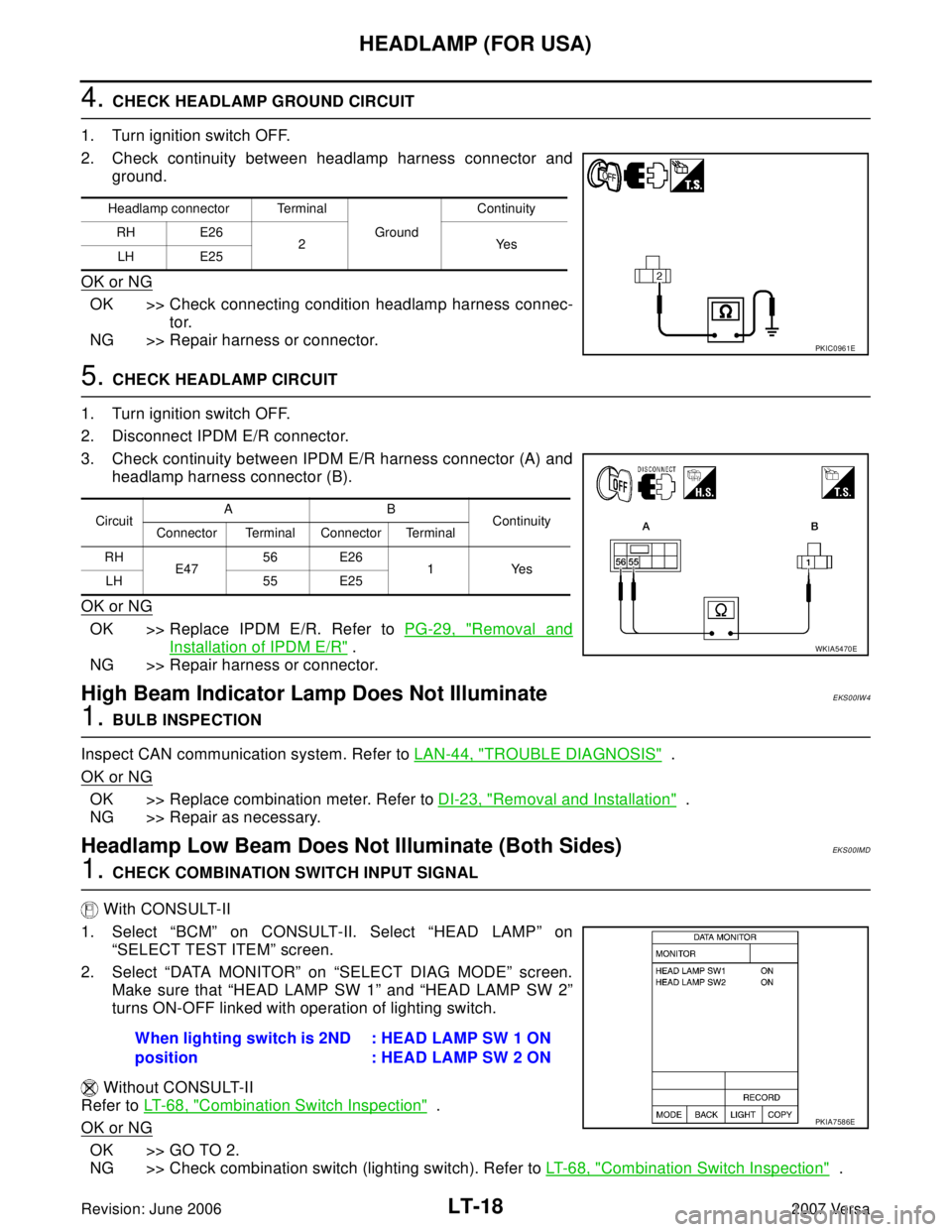
4. CHECK HEADLAMP GROUND CIRCUIT
1. Turn ignition switch OFF.
2. Check continuity between headlamp harness connector and
ground.
OK or NG
OK >> Check connecting condition headlamp harness connec-
tor.
NG >> Repair harness or connector.
5. CHECK HEADLAMP CIRCUIT
1. Turn ignition switch OFF.
2. Disconnect IPDM E/R connector.
3. Check continuity between IPDM E/R harness connector (A) and
headlamp harness connector (B).
OK or NG
OK >> Replace IPDM E/R. Refer to PG-29, "Removal and
Installation of IPDM E/R" .
NG >> Repair harness or connector.
High Beam Indicator Lamp Does Not IlluminateEKS00IW4
1. BULB INSPECTION
Inspect CAN communication system. Refer to LAN-44, "
TROUBLE DIAGNOSIS" .
OK or NG
OK >> Replace combination meter. Refer to DI-23, "Removal and Installation" .
NG >> Repair as necessary.
Headlamp Low Beam Does Not Illuminate (Both Sides)EKS00IMD
1. CHECK COMBINATION SWITCH INPUT SIGNAL
With CONSULT-II
1. Select “BCM” on CONSULT-II. Select “HEAD LAMP” on
“SELECT TEST ITEM” screen.
2. Select “DATA MONITOR” on “SELECT DIAG MODE” screen.
Make sure that “HEAD LAMP SW 1” and “HEAD LAMP SW 2”
turns ON-OFF linked with operation of lighting switch.
Without CONSULT-II
Refer to LT- 6 8 , "
Combination Switch Inspection" .
OK or NG
OK >> GO TO 2.
NG >> Check combination switch (lighting switch). Refer to LT- 6 8 , "
Combination Switch Inspection" .
Headlamp connector Terminal
Ground Continuity
RH E26
2Yes
LH E25
PKIC0961E
CircuitAB
Continuity
Connector Terminal Connector Terminal
RH
E47 56 E26
1Yes
LH 55 E25
WKIA5470E
When lighting switch is 2ND
position: HEAD LAMP SW 1 ON
: HEAD LAMP SW 2 ON
PKIA7586E
Page 2230 of 2896
LT-22
HEADLAMP (FOR USA)
Revision: June 20062007 Versa
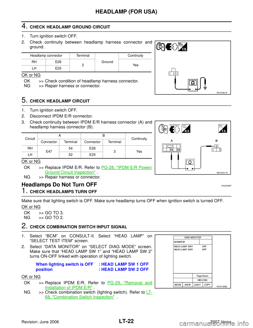
4. CHECK HEADLAMP GROUND CIRCUIT
1. Turn ignition switch OFF.
2. Check continuity between headlamp harness connector and
ground.
OK or NG
OK >> Check condition of headlamp harness connector.
NG >> Repair harness or connector.
5. CHECK HEADLAMP CIRCUIT
1. Turn ignition switch OFF.
2. Disconnect IPDM E/R connector.
3. Check continuity between IPDM E/R harness connector (A) and
headlamp harness connector (B).
OK or NG
OK >> Replace IPDM E/R. Refer to PG-28, "IPDM E/R Power/
Ground Circuit Inspection" .
NG >> Repair harness or connector.
Headlamps Do Not Turn OFFEKS00IMF
1. CHECK HEADLAMPS TURN OFF
Make sure that lighting switch is OFF. Make sure headlamp turns OFF when ignition switch is turned OFF.
OK or NG
OK >> GO TO 3.
NG >> GO TO 2.
2. CHECK COMBINATION SWITCH INPUT SIGNAL
1. Select “BCM” on CONSULT-II. Select “HEAD LAMP” on
“SELECT TEST ITEM” screen.
2. Select “DATA MONITOR” on “SELECT DIAG MODE” screen.
Make sure that “HEAD LAMP SW 1” and “HEAD LAMP SW 2”
turns ON-OFF linked with operation of lighting switch.
OK or NG
OK >> Replace IPDM E/R. Refer to PG-29, "Removal and
Installation of IPDM E/R" .
NG >> Check combination switch (lighting switch). Refer to LT-
68, "Combination Switch Inspection" .
Headlamp connector Terminal
Ground Continuity
RH E26
2Yes
LH E25
PKIC0961E
CircuitAB
Continuity
Connector Terminal Connector Terminal
RH
E4754 E26
3Yes
LH 52 E25
WKIA5471E
When lighting switch is OFF
position: HEAD LAMP SW 1 OFF
: HEAD LAMP SW 2 OFF
PKIA7588E
Page 2270 of 2896
LT-62
TURN SIGNAL AND HAZARD WARNING LAMPS
Revision: June 20062007 Versa
Hazard Warning Lamp Does Not Operate But Turn Signal Lamp OperatesEKS00HYA
1. CHECK HAZARD SWITCH INPUT SIGNAL
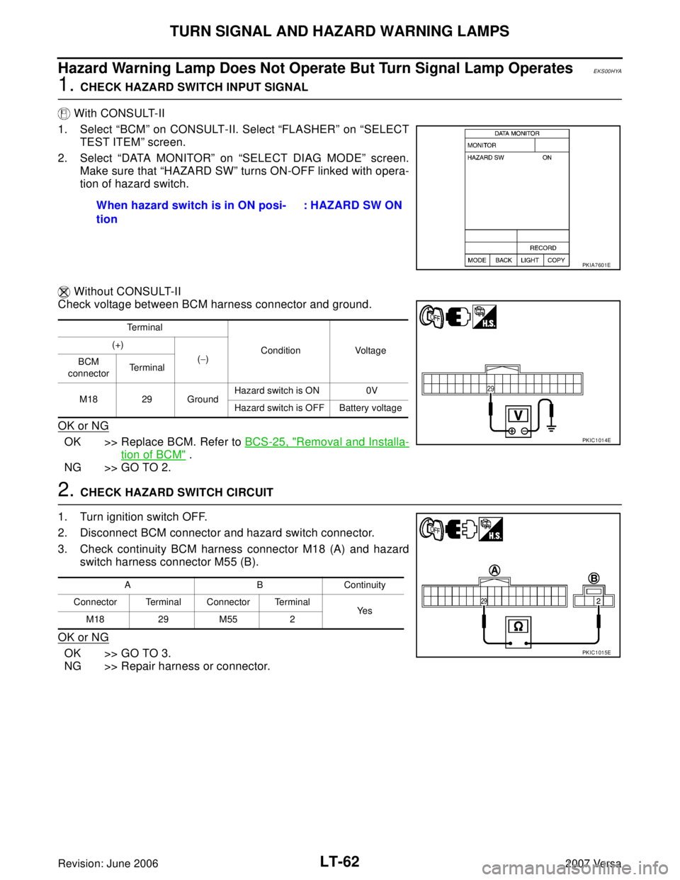
With CONSULT-II
1. Select “BCM” on CONSULT-II. Select “FLASHER” on “SELECT
TEST ITEM” screen.
2. Select “DATA MONITOR” on “SELECT DIAG MODE” screen.
Make sure that “HAZARD SW” turns ON-OFF linked with opera-
tion of hazard switch.
Without CONSULT-II
Check voltage between BCM harness connector and ground.
OK or NG
OK >> Replace BCM. Refer to BCS-25, "Removal and Installa-
tion of BCM" .
NG >> GO TO 2.
2. CHECK HAZARD SWITCH CIRCUIT
1. Turn ignition switch OFF.
2. Disconnect BCM connector and hazard switch connector.
3. Check continuity BCM harness connector M18 (A) and hazard
switch harness connector M55 (B).
OK or NG
OK >> GO TO 3.
NG >> Repair harness or connector.When hazard switch is in ON posi-
tion : HAZARD SW ON
PKIA7601E
Te r m i n a l
Condition Voltage (+)
(−)
BCM
connectorTe r m i n a l
M18 29 GroundHazard switch is ON 0V
Hazard switch is OFF Battery voltage
PKIC1014E
A B Continuity
Connector Terminal Connector Terminal
Ye s
M18 29 M55 2
PKIC1015E
Page 2271 of 2896
TURN SIGNAL AND HAZARD WARNING LAMPS
LT-63
C
D
E
F
G
H
I
J
L
MA
B
LT
Revision: June 20062007 Versa
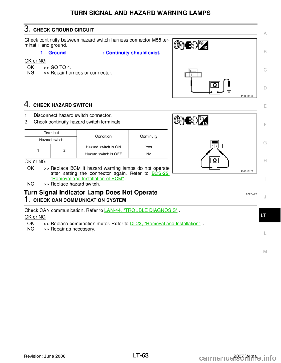
3. CHECK GROUND CIRCUIT
Check continuity between hazard switch harness connector M55 ter-
minal 1 and ground.
OK or NG
OK >> GO TO 4.
NG >> Repair harness or connector.
4. CHECK HAZARD SWITCH
1. Disconnect hazard switch connector.
2. Check continuity hazard switch terminals.
OK or NG
OK >> Replace BCM if hazard warning lamps do not operate
after setting the connector again. Refer to BCS-25,
"Removal and Installation of BCM" .
NG >> Replace hazard switch.
Turn Signal Indicator Lamp Does Not OperateEKS00J8H
1. CHECK CAN COMMUNICATION SYSTEM
Check CAN communication. Refer to LAN-44, "
TROUBLE DIAGNOSIS" .
OK or NG
OK >> Replace combination meter. Refer to DI-23, "Removal and Installation" .
NG >> Repair as necessary.1 – Ground : Continuity should exist.
PKIC1016E
Te r m i n a l
Condition Continuity
Hazard switch
12Hazard switch is ON Yes
Hazard switch is OFF No
PKIC1017E
Page 2312 of 2896
LT-104
INTERIOR ROOM LAMP
Revision: June 20062007 Versa
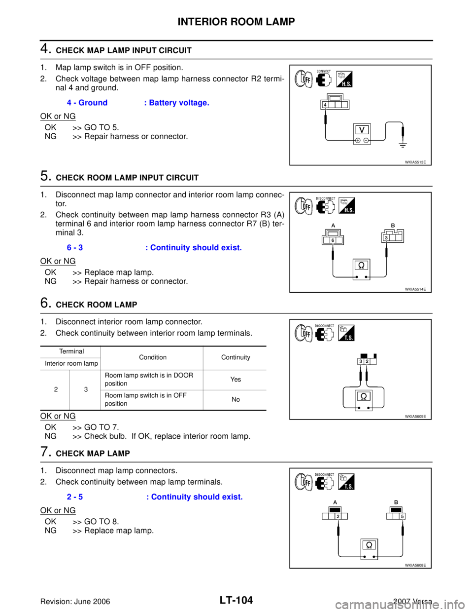
4. CHECK MAP LAMP INPUT CIRCUIT
1. Map lamp switch is in OFF position.
2. Check voltage between map lamp harness connector R2 termi-
nal 4 and ground.
OK or NG
OK >> GO TO 5.
NG >> Repair harness or connector.
5. CHECK ROOM LAMP INPUT CIRCUIT
1. Disconnect map lamp connector and interior room lamp connec-
tor.
2. Check continuity between map lamp harness connector R3 (A)
terminal 6 and interior room lamp harness connector R7 (B) ter-
minal 3.
OK or NG
OK >> Replace map lamp.
NG >> Repair harness or connector.
6. CHECK ROOM LAMP
1. Disconnect interior room lamp connector.
2. Check continuity between interior room lamp terminals.
OK or NG
OK >> GO TO 7.
NG >> Check bulb. If OK, replace interior room lamp.
7. CHECK MAP LAMP
1. Disconnect map lamp connectors.
2. Check continuity between map lamp terminals.
OK or NG
OK >> GO TO 8.
NG >> Replace map lamp.4 - Ground : Battery voltage.
WKIA5513E
6 - 3 : Continuity should exist.
WKIA5514E
Te r m i n a l
Condition Continuity
Interior room lamp
23Room lamp switch is in DOOR
positionYe s
Room lamp switch is in OFF
positionNo
WKIA5609E
2 - 5 : Continuity should exist.
WKIA5608E
Page 2314 of 2896
LT-106
INTERIOR ROOM LAMP
Revision: June 20062007 Versa
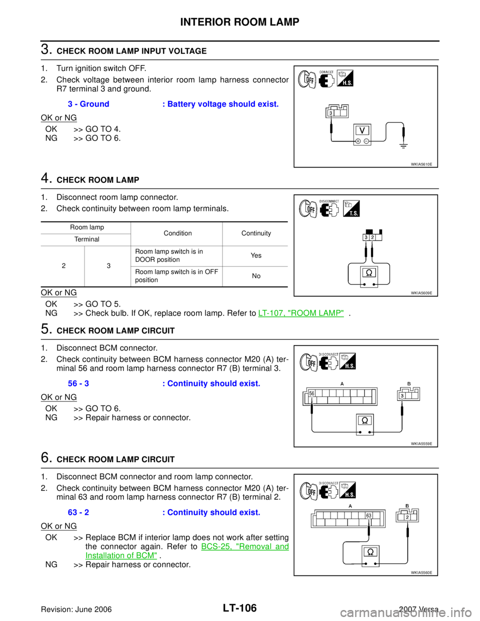
3. CHECK ROOM LAMP INPUT VOLTAGE
1. Turn ignition switch OFF.
2. Check voltage between interior room lamp harness connector
R7 terminal 3 and ground.
OK or NG
OK >> GO TO 4.
NG >> GO TO 6.
4. CHECK ROOM LAMP
1. Disconnect room lamp connector.
2. Check continuity between room lamp terminals.
OK or NG
OK >> GO TO 5.
NG >> Check bulb. If OK, replace room lamp. Refer to LT-107, "
ROOM LAMP" .
5. CHECK ROOM LAMP CIRCUIT
1. Disconnect BCM connector.
2. Check continuity between BCM harness connector M20 (A) ter-
minal 56 and room lamp harness connector R7 (B) terminal 3.
OK or NG
OK >> GO TO 6.
NG >> Repair harness or connector.
6. CHECK ROOM LAMP CIRCUIT
1. Disconnect BCM connector and room lamp connector.
2. Check continuity between BCM harness connector M20 (A) ter-
minal 63 and room lamp harness connector R7 (B) terminal 2.
OK or NG
OK >> Replace BCM if interior lamp does not work after setting
the connector again. Refer to BCS-25, "
Removal and
Installation of BCM" .
NG >> Repair harness or connector.3 - Ground : Battery voltage should exist.
WKIA5610E
Room lamp
Condition Continuity
Te r m i n a l
23 Room lamp switch is in
DOOR positionYe s
Room lamp switch is in OFF
positionNo
WKIA5609E
56 - 3 : Continuity should exist.
WKIA5559E
63 - 2 : Continuity should exist.
WKIA5560E
Page 2335 of 2896
MA-1
MAINTENANCE
L MAINTENANCE
CONTENTS
C
D
E
F
G
H
I
J
K
M
SECTION MA
A
B
MA
Revision: June 20062007 Versa PRECAUTIONS .......................................................... 3
Precautions for Supplemental Restraint System
(SRS) “AIR BAG” and “SEAT BELT PRE-TEN-
SIONER” .................................................................. 3
PREPARATION ........................................................... 4
Special Service Tools ............................................... 4
Commercial Service Tools ........................................ 4
GENERAL MAINTENANCE ....................................... 5
Explanation of General Maintenance ....................... 5
General Maintenance ............................................... 5
PERIODIC MAINTENANCE ....................................... 7
Introduction of Periodic Maintenance ....................... 7
Schedule 1 ............................................................... 7
EMISSION CONTROL SYSTEM MAINTE-
NANCE .................................................................. 7
CHASSIS AND BODY MAINTENANCE ............... 8
Schedule 2 ............................................................... 9
EMISSION CONTROL SYSTEM MAINTE-
NANCE .................................................................. 9
CHASSIS AND BODY MAINTENANCE ............. 10
RECOMMENDED FLUIDS AND LUBRICANTS .......11
Fluids and Lubricants ..............................................11
SAE Viscosity Number ........................................... 12
Anti-freeze Coolant Mixture Ratio .......................... 12
ENGINE MAINTENANCE ......................................... 13
Drive Belts .............................................................. 13
Checking Drive Belts .............................................. 13
Tension Adjustment ................................................ 13
Changing Engine Coolant ...................................... 13
DRAINING ENGINE COOLANT ......................... 13
REFILLING ENGINE COOLANT ........................ 14
FLUSHING COOLING SYSTEM ......................... 15
Inspection ............................................................... 15
LEVEL CHECK ................................................... 15
CHECKING COOLING SYSTEM FOR LEAKS ... 15
Checking Fuel Lines ............................................... 15
Changing Air Cleaner Filter .................................... 16
REMOVAL ........................................................... 16
INSPECTION AFTER REMOVAL ....................... 16
INSTALLATION ................................................... 16Changing Engine Oil ............................................... 16
Engine Oil Filter ...................................................... 17
REMOVAL ........................................................... 17
INSTALLATION ................................................... 17
INSPECTION AFTER INSTALLATION ................ 18
Changing Spark Plugs ............................................ 18
............................................................................ 18
INSPECTION AFTER REMOVAL ....................... 18
INSTALLATION ................................................... 19
Checking EVAP Vapor Lines .................................. 19
CHASSIS AND BODY MAINTENANCE ................... 20
Changing In-cabin Microfilter .................................. 20
Checking Exhaust System ...................................... 20
Checking CVT Fluid ................................................ 20
FLUID LEVEL CHECK ........................................ 20
FLUID CONDITION CHECK ............................... 21
Changing CVT Fluid ............................................... 21
Checking Clutch Fluid Level and Leaks ................. 22
Checking Clutch System ........................................ 22
Checking M/T Oil .................................................... 22
OIL LEAKAGE AND OIL LEVEL ......................... 22
Changing M/T Oil .................................................... 22
DRAINING ........................................................... 22
FILLING ............................................................... 22
Checking A/T Fluid ................................................. 22
Changing A/T Fluid ................................................. 23
Balancing Wheels ................................................... 24
Rotation .................................................................. 24
Checking Brake Fluid Level and Leaks .................. 24
Checking Brake Lines and Cables ......................... 24
Changing Brake Fluid ............................................. 25
Checking Disc Brake .............................................. 25
ROTOR ................................................................ 25
CALIPER ............................................................. 25
PAD ..................................................................... 25
WHEEL CYLINDER ............................................ 26
LINING ................................................................ 26
Axle and Suspension Parts .................................... 26
Drive Shaft .............................................................. 27