Page 1395 of 2896
EC-226Revision: June 2006
DTC P0130 A/F SENSOR 1
2007 Versa
5. CHECK INTERMITTENT INCIDENT
Perform EC-143, "
TROUBLE DIAGNOSIS FOR INTERMITTENT INCIDENT" .
OK or NG
OK >> GO TO 6.
NG >> Repair or replace.
6. REPLACE AIR FUEL RATIO (A/F) SENSOR 1
Replace air fuel ratio (A/F) sensor 1.
CAUTION:
�Discard any A/F sensor which has been dropped from a height of more than 0.5 m (19.7 in) onto a
hard surface such as a concrete floor; use a new one.
�Before installing new A/F sensor, clean exhaust system threads using Oxygen Sensor Thread
Cleaner tool J-43897-18 or J-43897-12 and approved anti-seize lubricant.
>>INSPECTION END
Removal and InstallationUBS00QES
AIR FUEL RATIO SENSOR
Refer to EM-21, "EXHAUST MANIFOLD"
Page 1401 of 2896
EC-232Revision: June 2006
DTC P0131 A/F SENSOR 1
2007 Versa
5. CHECK INTERMITTENT INCIDENT
Perform EC-143, "
TROUBLE DIAGNOSIS FOR INTERMITTENT INCIDENT" .
OK or NG
OK >> GO TO 6.
NG >> Repair or replace.
6. REPLACE AIR FUEL RATIO (A/F) SENSOR 1
Replace air fuel ratio (A/F) sensor 1.
CAUTION:
�Discard any A/F sensor which has been dropped from a height of more than 0.5 m (19.7 in) onto a
hard surface such as a concrete floor; use a new one.
�Before installing new A/F sensor, clean exhaust system threads using Oxygen Sensor Thread
Cleaner tool J-43897-18 or J-43897-12 and approved anti-seize lubricant.
>>INSPECTION END
Removal and InstallationUBS00QEZ
AIR FUEL RATIO SENSOR
Refer to EM-21, "EXHAUST MANIFOLD" .
Page 1407 of 2896
EC-238Revision: June 2006
DTC P0132 A/F SENSOR 1
2007 Versa
5. CHECK INTERMITTENT INCIDENT
Perform EC-143, "
TROUBLE DIAGNOSIS FOR INTERMITTENT INCIDENT" .
OK or NG
OK >> GO TO 6.
NG >> Repair or replace.
6. REPLACE AIR FUEL RATIO (A/F) SENSOR 1
Replace air fuel ratio (A/F) sensor 1.
CAUTION:
�Discard any A/F sensor which has been dropped from a height of more than 0.5 m (19.7 in) onto a
hard surface such as a concrete floor; use a new one.
�Before installing new A/F sensor, clean exhaust system threads using Oxygen Sensor Thread
Cleaner tool J-43897-18 or J-43897-12 and approved anti-seize lubricant.
>>INSPECTION END
Removal and InstallationUBS00QF6
AIR FUEL RATIO SENSOR
Refer to EM-21, "EXHAUST MANIFOLD" .
Page 1416 of 2896

DTC P0133 A/F SENSOR 1
EC-247
C
D
E
F
G
H
I
J
K
L
MA
EC
Revision: June 20062007 Versa
9. CHECK AIR FUEL RATIO (A/F) SENSOR 1 HEATER
Refer to EC-165, "
Component Inspection" .
OK or NG
OK >> GO TO 10.
NG >> GO TO 13.
10. CHECK MASS AIR FLOW SENSOR
Refer to EC-185, "
Component Inspection" .
OK or NG
OK >> GO TO 11.
NG >> Replace mass air flow sensor.
11 . CHECK PCV VALVE
Refer to EC-44, "
Component Inspection" .
OK or NG
OK >> GO TO 12.
NG >> Repair or replace PCV valve.
12. CHECK INTERMITTENT INCIDENT
Perform EC-143, "
TROUBLE DIAGNOSIS FOR INTERMITTENT INCIDENT" .
OK or NG
OK >> GO TO 13.
NG >> Repair or replace.
13. REPLACE AIR FUEL RATIO (A/F) SENSOR 1
Replace air fuel ratio (A/F) sensor 1.
CAUTION:
�Discard any A/F sensor which has been dropped from a height of more than 0.5 m (19.7 in) onto a
hard surface such as a concrete floor; use a new one.
�Before installing new A/F sensor, clean exhaust system threads using Oxygen Sensor Thread
Cleaner tool J-43897-18 or J-43897-12 and approved anti-seize lubricant.
>>INSPECTION END
Removal and InstallationUBS00QFD
AIR FUEL RATIO SENSOR
Refer to EM-21, "EXHAUST MANIFOLD" .
Page 1425 of 2896

EC-256Revision: June 2006
DTC P0137 HO2S2
2007 Versa
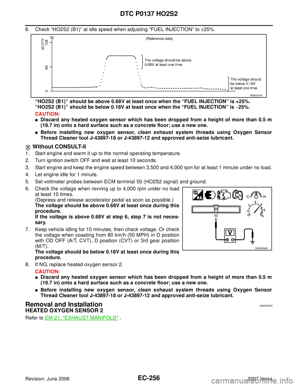
6. Check “HO2S2 (B1)” at idle speed when adjusting “FUEL INJECTION” to ±25%.
“HO2S2 (B1)” should be above 0.68V at least once when the “FUEL INJECTION” is +25%.
“HO2S2 (B1)” should be below 0.18V at least once when the “FUEL INJECTION” is −25%.
CAUTION:
�Discard any heated oxygen sensor which has been dropped from a height of more than 0.5 m
(19.7 in) onto a hard surface such as a concrete floor; use a new one.
�Before installing new oxygen sensor, clean exhaust system threads using Oxygen Sensor
Thread Cleaner tool J-43897-18 or J-43897-12 and approved anti-seize lubricant.
Without CONSULT-II
1. Start engine and warm it up to the normal operating temperature.
2. Turn ignition switch OFF and wait at least 10 seconds.
3. Start engine and keep the engine speed between 3,500 and 4,000 rpm for at least 1 minute under no load.
4. Let engine idle for 1 minute.
5. Set voltmeter probes between ECM terminal 50 (HO2S2 signal) and ground.
6. Check the voltage when revving up to 4,000 rpm under no load
at least 10 times.
(Depress and release accelerator pedal as soon as possible.)
The voltage should be above 0.68V at least once during this
procedure.
If the voltage is above 0.68V at step 6, step 7 is not neces-
sary.
7. Keep vehicle idling for 10 minutes, then check voltage. Or check
the voltage when coasting from 80 km/h (50 MPH) in D position
with OD OFF (A/T, CVT), D position (CVT) or 3rd gear position
(M/T).
The voltage should be below 0.18V at least once during this
procedure.
8. If NG, replace heated oxygen sensor 2.
CAUTION:
�Discard any heated oxygen sensor which has been dropped from a height of more than 0.5 m
(19.7 in) onto a hard surface such as a concrete floor; use a new one.
�Before installing new oxygen sensor, clean exhaust system threads using Oxygen Sensor
Thread Cleaner tool J-43897-18 or J-43897-12 and approved anti-seize lubricant.
Removal and InstallationUBS00QFM
HEATED OXYGEN SENSOR 2
Refer to EM-21, "EXHAUST MANIFOLD" .
PBIB2534E
PBIB2996E
Page 1435 of 2896

EC-266Revision: June 2006
DTC P0138 HO2S2
2007 Versa
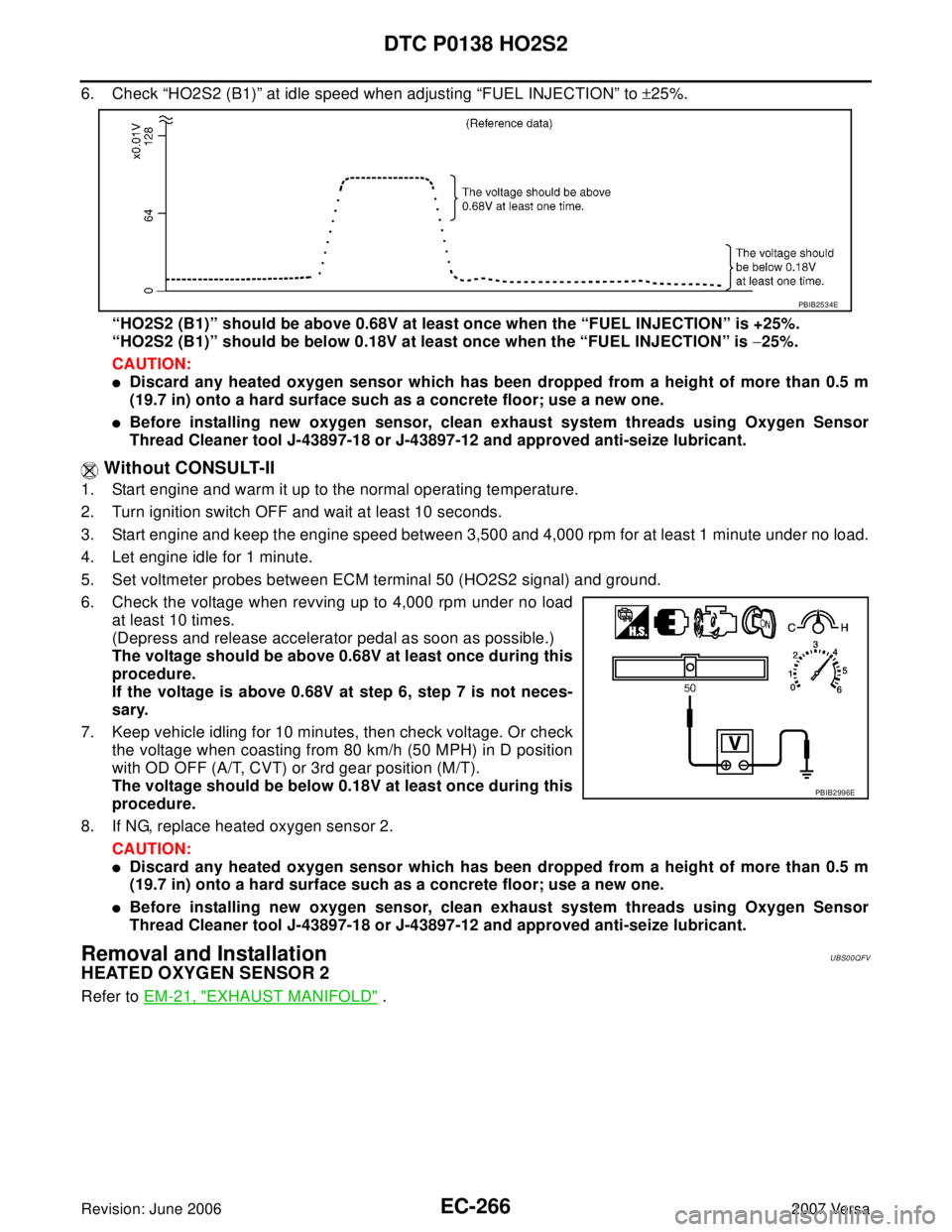
6. Check “HO2S2 (B1)” at idle speed when adjusting “FUEL INJECTION” to ±25%.
“HO2S2 (B1)” should be above 0.68V at least once when the “FUEL INJECTION” is +25%.
“HO2S2 (B1)” should be below 0.18V at least once when the “FUEL INJECTION” is −25%.
CAUTION:
�Discard any heated oxygen sensor which has been dropped from a height of more than 0.5 m
(19.7 in) onto a hard surface such as a concrete floor; use a new one.
�Before installing new oxygen sensor, clean exhaust system threads using Oxygen Sensor
Thread Cleaner tool J-43897-18 or J-43897-12 and approved anti-seize lubricant.
Without CONSULT-II
1. Start engine and warm it up to the normal operating temperature.
2. Turn ignition switch OFF and wait at least 10 seconds.
3. Start engine and keep the engine speed between 3,500 and 4,000 rpm for at least 1 minute under no load.
4. Let engine idle for 1 minute.
5. Set voltmeter probes between ECM terminal 50 (HO2S2 signal) and ground.
6. Check the voltage when revving up to 4,000 rpm under no load
at least 10 times.
(Depress and release accelerator pedal as soon as possible.)
The voltage should be above 0.68V at least once during this
procedure.
If the voltage is above 0.68V at step 6, step 7 is not neces-
sary.
7. Keep vehicle idling for 10 minutes, then check voltage. Or check
the voltage when coasting from 80 km/h (50 MPH) in D position
with OD OFF (A/T, CVT) or 3rd gear position (M/T).
The voltage should be below 0.18V at least once during this
procedure.
8. If NG, replace heated oxygen sensor 2.
CAUTION:
�Discard any heated oxygen sensor which has been dropped from a height of more than 0.5 m
(19.7 in) onto a hard surface such as a concrete floor; use a new one.
�Before installing new oxygen sensor, clean exhaust system threads using Oxygen Sensor
Thread Cleaner tool J-43897-18 or J-43897-12 and approved anti-seize lubricant.
Removal and InstallationUBS00QFV
HEATED OXYGEN SENSOR 2
Refer to EM-21, "EXHAUST MANIFOLD" .
PBIB2534E
PBIB2996E
Page 1444 of 2896

DTC P0139 HO2S2
EC-275
C
D
E
F
G
H
I
J
K
L
MA
EC
Revision: June 20062007 Versa
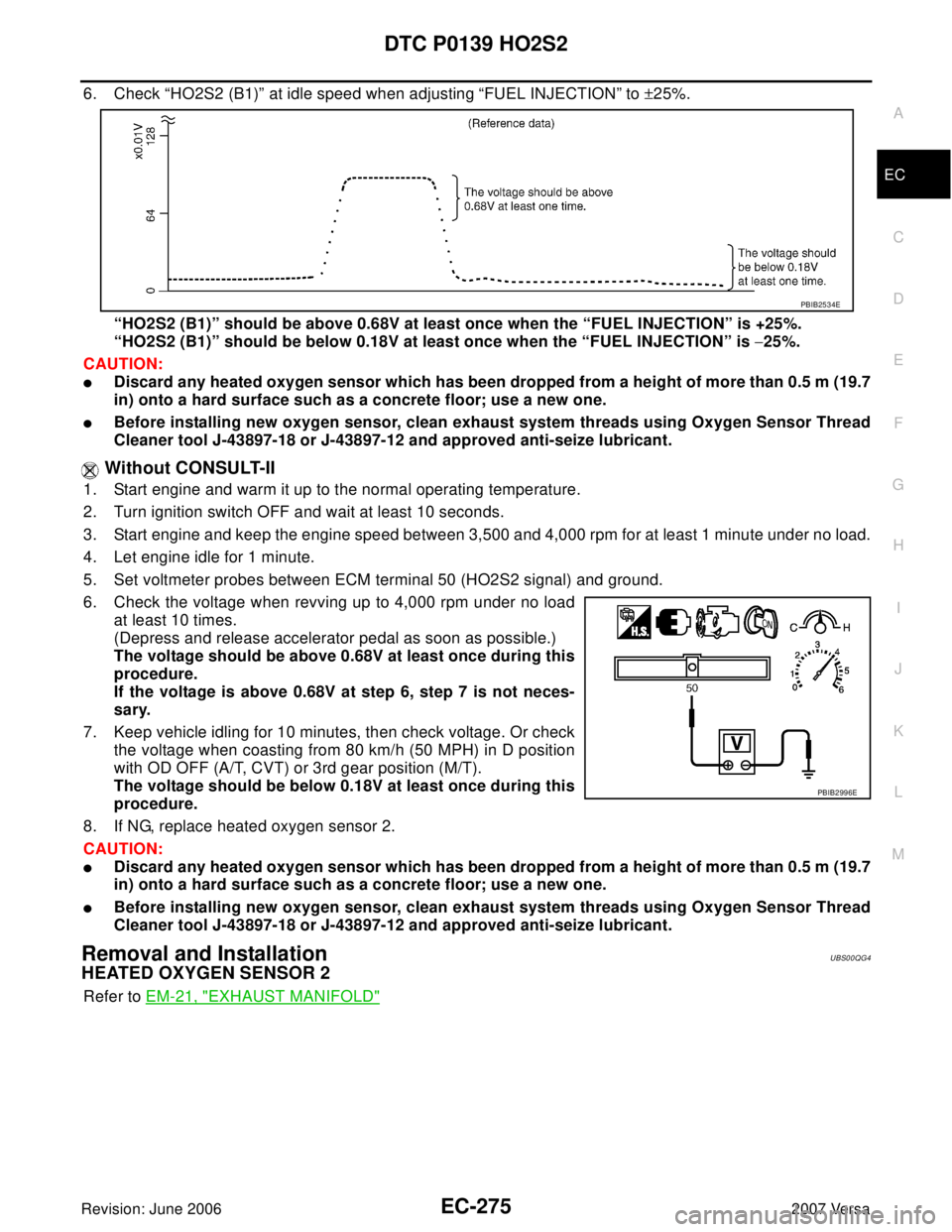
6. Check “HO2S2 (B1)” at idle speed when adjusting “FUEL INJECTION” to ±25%.
“HO2S2 (B1)” should be above 0.68V at least once when the “FUEL INJECTION” is +25%.
“HO2S2 (B1)” should be below 0.18V at least once when the “FUEL INJECTION” is −25%.
CAUTION:
�Discard any heated oxygen sensor which has been dropped from a height of more than 0.5 m (19.7
in) onto a hard surface such as a concrete floor; use a new one.
�Before installing new oxygen sensor, clean exhaust system threads using Oxygen Sensor Thread
Cleaner tool J-43897-18 or J-43897-12 and approved anti-seize lubricant.
Without CONSULT-II
1. Start engine and warm it up to the normal operating temperature.
2. Turn ignition switch OFF and wait at least 10 seconds.
3. Start engine and keep the engine speed between 3,500 and 4,000 rpm for at least 1 minute under no load.
4. Let engine idle for 1 minute.
5. Set voltmeter probes between ECM terminal 50 (HO2S2 signal) and ground.
6. Check the voltage when revving up to 4,000 rpm under no load
at least 10 times.
(Depress and release accelerator pedal as soon as possible.)
The voltage should be above 0.68V at least once during this
procedure.
If the voltage is above 0.68V at step 6, step 7 is not neces-
sary.
7. Keep vehicle idling for 10 minutes, then check voltage. Or check
the voltage when coasting from 80 km/h (50 MPH) in D position
with OD OFF (A/T, CVT) or 3rd gear position (M/T).
The voltage should be below 0.18V at least once during this
procedure.
8. If NG, replace heated oxygen sensor 2.
CAUTION:
�Discard any heated oxygen sensor which has been dropped from a height of more than 0.5 m (19.7
in) onto a hard surface such as a concrete floor; use a new one.
�Before installing new oxygen sensor, clean exhaust system threads using Oxygen Sensor Thread
Cleaner tool J-43897-18 or J-43897-12 and approved anti-seize lubricant.
Removal and InstallationUBS00QG4
HEATED OXYGEN SENSOR 2
Refer to EM-21, "EXHAUST MANIFOLD"
PBIB2534E
PBIB2996E
Page 1483 of 2896

EC-314Revision: June 2006
DTC P0300 - P0304 MULTIPLE CYLINDER MISFIRE, NO. 1 - 4 CYLINDER MIS-
FIRE
2007 Versa
15. REPLACE AIR FUEL RATIO (A/F) SENSOR 1
Replace air fuel ratio (A/F) sensor 1.
CAUTION:
�Discard any A/F sensor which has been dropped from a height of more than 0.5 m (19.7 in) onto a
hard surface such as a concrete floor; use a new one.
�Before installing new A/F sensor, clean exhaust system threads using Oxygen Sensor Thread
Cleaner tool J-43897-18 or J-43897-12 and approved anti-seize lubricant.
>>INSPECTION END
16. CHECK MASS AIR FLOW SENSOR
With CONSULT-II
1. Start engine and warm it up to normal operating temperature.
2. Check mass air flow sensor signal in “DATA MONITOR” mode with CONSULT-II.
With GST
1. Start engine and warm it up to normal operating temperature.
2. Check mass air flow sensor signal in Service $01 with GST.
OK or NG
OK >> GO TO 17.
NG >> Check connectors for rusted terminals or loose connections in the mass air flow sensor circuit or
ground. Refer to EC-178, "
DTC P0101 MAF SENSOR" .
17. CHECK SYMPTOM MATRIX CHART
Check items on the rough idle symptom in EC-92, "
Symptom Matrix Chart" .
OK or NG
OK >> GO TO 18.
NG >> Repair or replace.
18. ERASE THE 1ST TRIP DTC
Some tests may cause a 1st trip DTC to be set.
Erase the 1st trip DTC from the ECM memory after performing the tests. Refer to EC-60, "
HOW TO ERASE
EMISSION-RELATED DIAGNOSTIC INFORMATION" .
>> GO TO 19.
19. CHECK INTERMITTENT INCIDENT
Refer to EC-143, "
TROUBLE DIAGNOSIS FOR INTERMITTENT INCIDENT" .
>>INSPECTION END at idling : 1.0 - 4.0 g·m/sec
at 2,500 rpm : 2.0 - 10.0 g·m/sec
at idling : 1.0 - 4.0 g·m/sec
at 2,500 rpm : 2.0 - 10.0 g·m/sec