Page 1644 of 2896
DTC P1572 ASCD BRAKE SWITCH
EC-475
C
D
E
F
G
H
I
J
K
L
MA
EC
Revision: June 20062007 Versa
Wiring Diagram UBS00QLQ
BBWA2665E
Page 1647 of 2896
EC-478Revision: June 2006
DTC P1572 ASCD BRAKE SWITCH
2007 Versa
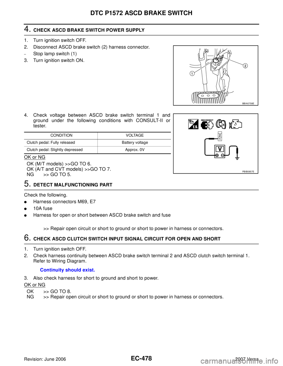
4. CHECK ASCD BRAKE SWITCH POWER SUPPLY
1. Turn ignition switch OFF.
2. Disconnect ASCD brake switch (2) harness connector.
–Stop lamp switch (1)
3. Turn ignition switch ON.
4. Check voltage between ASCD brake switch terminal 1 and
ground under the following conditions with CONSULT-II or
tester.
OK or NG
OK (M/T models) >>GO TO 6.
OK (A/T and CVT models) >>GO TO 7.
NG >> GO TO 5.
5. DETECT MALFUNCTIONING PART
Check the following.
�Harness connectors M69, E7
�10A fuse
�Harness for open or short between ASCD brake switch and fuse
>> Repair open circuit or short to ground or short to power in harness or connectors.
6. CHECK ASCD CLUTCH SWITCH INPUT SIGNAL CIRCUIT FOR OPEN AND SHORT
1. Turn ignition switch OFF.
2. Check harness continuity between ASCD brake switch terminal 2 and ASCD clutch switch terminal 1.
Refer to Wiring Diagram.
3. Also check harness for short to ground and short to power.
OK or NG
OK >> GO TO 8.
NG >> Repair open circuit or short to ground or short to power in harness or connectors.
BBIA0708E
CONDITION VOLTAGE
Clutch pedal: Fully released Battery voltage
Clutch pedal: Slightly depressed Approx. 0V
PBIB0857E
Continuity should exist.
Page 1648 of 2896
DTC P1572 ASCD BRAKE SWITCH
EC-479
C
D
E
F
G
H
I
J
K
L
MA
EC
Revision: June 20062007 Versa
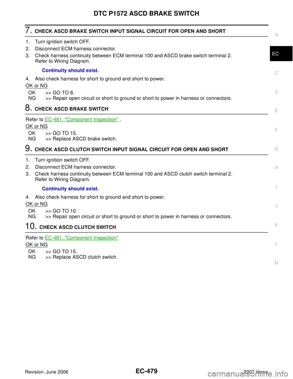
7. CHECK ASCD BRAKE SWITCH INPUT SIGNAL CIRCUIT FOR OPEN AND SHORT
1. Turn ignition switch OFF.
2. Disconnect ECM harness connector.
3. Check harness continuity between ECM terminal 100 and ASCD brake switch terminal 2.
Refer to Wiring Diagram.
4. Also check harness for short to ground and short to power.
OK or NG
OK >> GO TO 8.
NG >> Repair open circuit or short to ground or short to power in harness or connectors.
8. CHECK ASCD BRAKE SWITCH
Refer to EC-481, "
Component Inspection" .
OK or NG
OK >> GO TO 15.
NG >> Replace ASCD brake switch.
9. CHECK ASCD CLUTCH SWITCH INPUT SIGNAL CIRCUIT FOR OPEN AND SHORT
1. Turn ignition switch OFF.
2. Disconnect ECM harness connector.
3. Check harness continuity between ECM terminal 100 and ASCD clutch switch terminal 2.
Refer to Wiring Diagram.
4. Also check harness for short to ground and short to power.
OK or NG
OK >> GO TO 10.
NG >> Repair open circuit or short to ground or short to power in harness or connectors.
10. CHECK ASCD CLUTCH SWITCH
Refer to EC-481, "
Component Inspection"
OK or NG
OK >> GO TO 15.
NG >> Replace ASCD clutch switch.Continuity should exist.
Continuity should exist.
Page 1649 of 2896
EC-480Revision: June 2006
DTC P1572 ASCD BRAKE SWITCH
2007 Versa
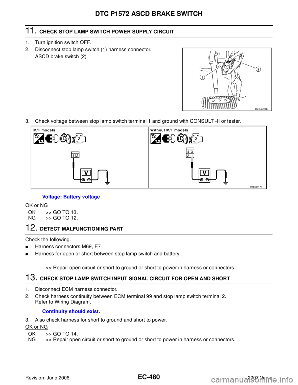
11 . CHECK STOP LAMP SWITCH POWER SUPPLY CIRCUIT
1. Turn ignition switch OFF.
2. Disconnect stop lamp switch (1) harness connector.
–ASCD brake switch (2)
3. Check voltage between stop lamp switch terminal 1 and ground with CONSULT -II or tester.
OK or NG
OK >> GO TO 13.
NG >> GO TO 12.
12. DETECT MALFUNCTIONING PART
Check the following.
�Harness connectors M69, E7
�Harness for open or short between stop lamp switch and battery
>> Repair open circuit or short to ground or short to power in harness or connectors.
13. CHECK STOP LAMP SWITCH INPUT SIGNAL CIRCUIT FOR OPEN AND SHORT
1. Disconnect ECM harness connector.
2. Check harness continuity between ECM terminal 99 and stop lamp switch terminal 2.
Refer to Wiring Diagram.
3. Also check harness for short to ground and short to power.
OK or NG
OK >> GO TO 14.
NG >> Repair open circuit or short to ground or short to power in harness or connectors.
BBIA0708E
Voltage: Battery voltage
PBIB3317E
Continuity should exist.
Page 1658 of 2896
DTC P1805 BRAKE SWITCH
EC-489
C
D
E
F
G
H
I
J
K
L
MA
EC
Revision: June 20062007 Versa
Wiring DiagramUBS00QM2
BBWA2651E
Page 1660 of 2896
DTC P1805 BRAKE SWITCH
EC-491
C
D
E
F
G
H
I
J
K
L
MA
EC
Revision: June 20062007 Versa
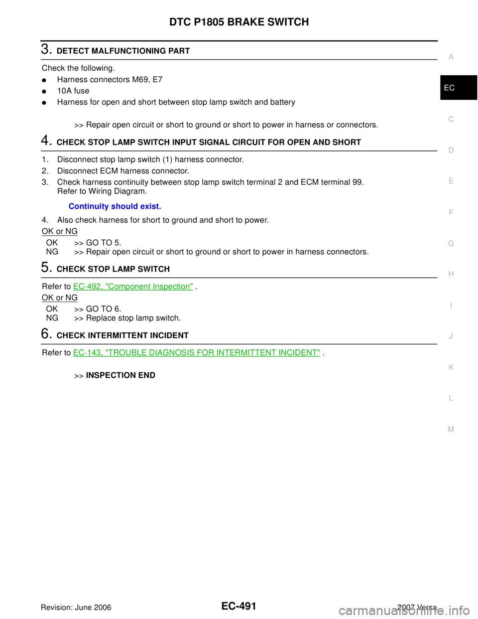
3. DETECT MALFUNCTIONING PART
Check the following.
�Harness connectors M69, E7
�10A fuse
�Harness for open and short between stop lamp switch and battery
>> Repair open circuit or short to ground or short to power in harness or connectors.
4. CHECK STOP LAMP SWITCH INPUT SIGNAL CIRCUIT FOR OPEN AND SHORT
1. Disconnect stop lamp switch (1) harness connector.
2. Disconnect ECM harness connector.
3. Check harness continuity between stop lamp switch terminal 2 and ECM terminal 99.
Refer to Wiring Diagram.
4. Also check harness for short to ground and short to power.
OK or NG
OK >> GO TO 5.
NG >> Repair open circuit or short to ground or short to power in harness connectors.
5. CHECK STOP LAMP SWITCH
Refer to EC-492, "
Component Inspection" .
OK or NG
OK >> GO TO 6.
NG >> Replace stop lamp switch.
6. CHECK INTERMITTENT INCIDENT
Refer to EC-143, "
TROUBLE DIAGNOSIS FOR INTERMITTENT INCIDENT" .
>>INSPECTION END Continuity should exist.
Page 1664 of 2896
DTC P2100, P2103 THROTTLE CONTROL MOTOR RELAY
EC-495
C
D
E
F
G
H
I
J
K
L
MA
EC
Revision: June 20062007 Versa
Wiring DiagramUBS00QM9
BBWA2644E
Page 1666 of 2896
DTC P2100, P2103 THROTTLE CONTROL MOTOR RELAY
EC-497
C
D
E
F
G
H
I
J
K
L
MA
EC
Revision: June 20062007 Versa
2. CHECK THROTTLE CONTROL MOTOR RELAY POWER SUPPLY CIRCUIT-II
1. Disconnect ECM harness connector.
2. Disconnect IPDM E/R harness connector E46.
3. Check continuity between ECM terminal 15 and IPDM E/R terminal 46.
Refer to Wiring Diagram.
4. Also check harness for short to ground and short to power.
OK or NG
OK >> GO TO 4.
NG >> GO TO 3.
3. DETECT MALFUNCTIONING PART
Check the following.
�Harness connectors E8, F8
�Harness for open or short between ECM and IPDM E/R
>> Repair open circuit or short to ground or short to power in harness or connectors.
4. CHECK FUSE
1. Disconnect 15A fuse.
2. Check 15A fuse for blown.
OK or NG
OK >> GO TO 8.
NG >> Replace 15A fuse.
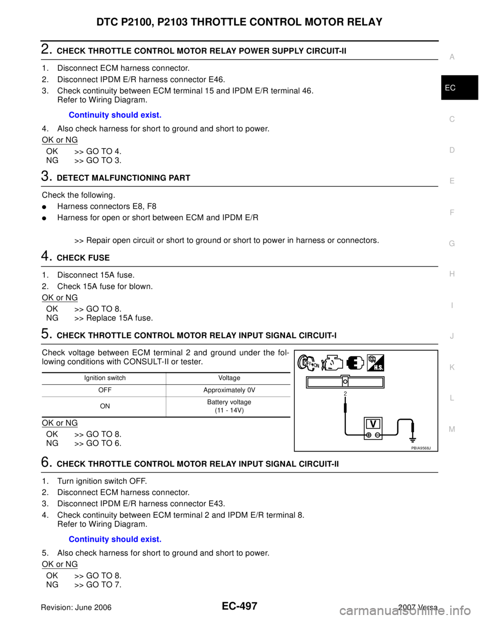
5. CHECK THROTTLE CONTROL MOTOR RELAY INPUT SIGNAL CIRCUIT-I
Check voltage between ECM terminal 2 and ground under the fol-
lowing conditions with CONSULT-II or tester.
OK or NG
OK >> GO TO 8.
NG >> GO TO 6.
6. CHECK THROTTLE CONTROL MOTOR RELAY INPUT SIGNAL CIRCUIT-II
1. Turn ignition switch OFF.
2. Disconnect ECM harness connector.
3. Disconnect IPDM E/R harness connector E43.
4. Check continuity between ECM terminal 2 and IPDM E/R terminal 8.
Refer to Wiring Diagram.
5. Also check harness for short to ground and short to power.
OK or NG
OK >> GO TO 8.
NG >> GO TO 7.Continuity should exist.
Ignition switch Voltage
OFF Approximately 0V
ONBattery voltage
(11 - 14V)
PBIA9568J
Continuity should exist.