Page 1527 of 2896

EC-358Revision: June 2006
DTC P0443 EVAP CANISTER PURGE VOLUME CONTROL SOLENOID VALVE
2007 Versa
Diagnostic ProcedureUBS00QI5
1. CHECK EVAP CANISTER PURGE VOLUME CONTROL SOLENOID VALVE POWER SUPPLY CIR-
CUIT
1. Turn ignition switch OFF.
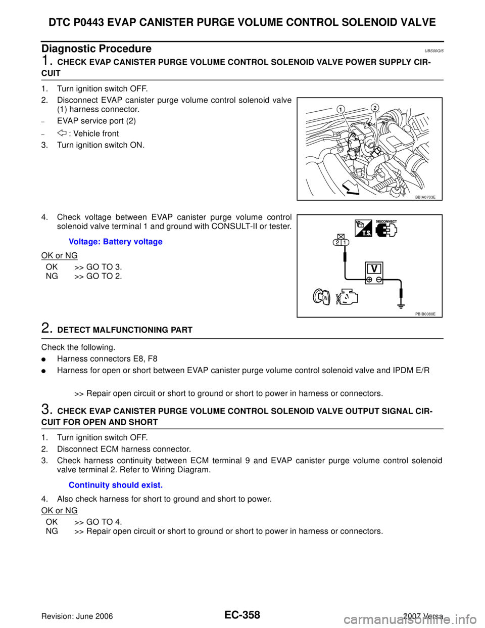
2. Disconnect EVAP canister purge volume control solenoid valve
(1) harness connector.
–EVAP service port (2)
– : Vehicle front
3. Turn ignition switch ON.
4. Check voltage between EVAP canister purge volume control
solenoid valve terminal 1 and ground with CONSULT-II or tester.
OK or NG
OK >> GO TO 3.
NG >> GO TO 2.
2. DETECT MALFUNCTIONING PART
Check the following.
�Harness connectors E8, F8
�Harness for open or short between EVAP canister purge volume control solenoid valve and IPDM E/R
>> Repair open circuit or short to ground or short to power in harness or connectors.
3. CHECK EVAP CANISTER PURGE VOLUME CONTROL SOLENOID VALVE OUTPUT SIGNAL CIR-
CUIT FOR OPEN AND SHORT
1. Turn ignition switch OFF.
2. Disconnect ECM harness connector.
3. Check harness continuity between ECM terminal 9 and EVAP canister purge volume control solenoid
valve terminal 2. Refer to Wiring Diagram.
4. Also check harness for short to ground and short to power.
OK or NG
OK >> GO TO 4.
NG >> Repair open circuit or short to ground or short to power in harness or connectors.
BBIA0703E
Voltage: Battery voltage
PBIB0080E
Continuity should exist.
Page 1533 of 2896
EC-364Revision: June 2006
DTC P0444, P0445 EVAP CANISTER PURGE VOLUME CONTROL SOLENOID
VALVE
2007 Versa
Wiring DiagramUBS00QIC
BBWA2640E
Page 1535 of 2896

EC-366Revision: June 2006
DTC P0444, P0445 EVAP CANISTER PURGE VOLUME CONTROL SOLENOID
VALVE
2007 Versa
Diagnostic ProcedureUBS00QID
1. CHECK EVAP CANISTER PURGE VOLUME CONTROL SOLENOID VALVE POWER SUPPLY CIR-
CUIT
1. Turn ignition switch OFF.
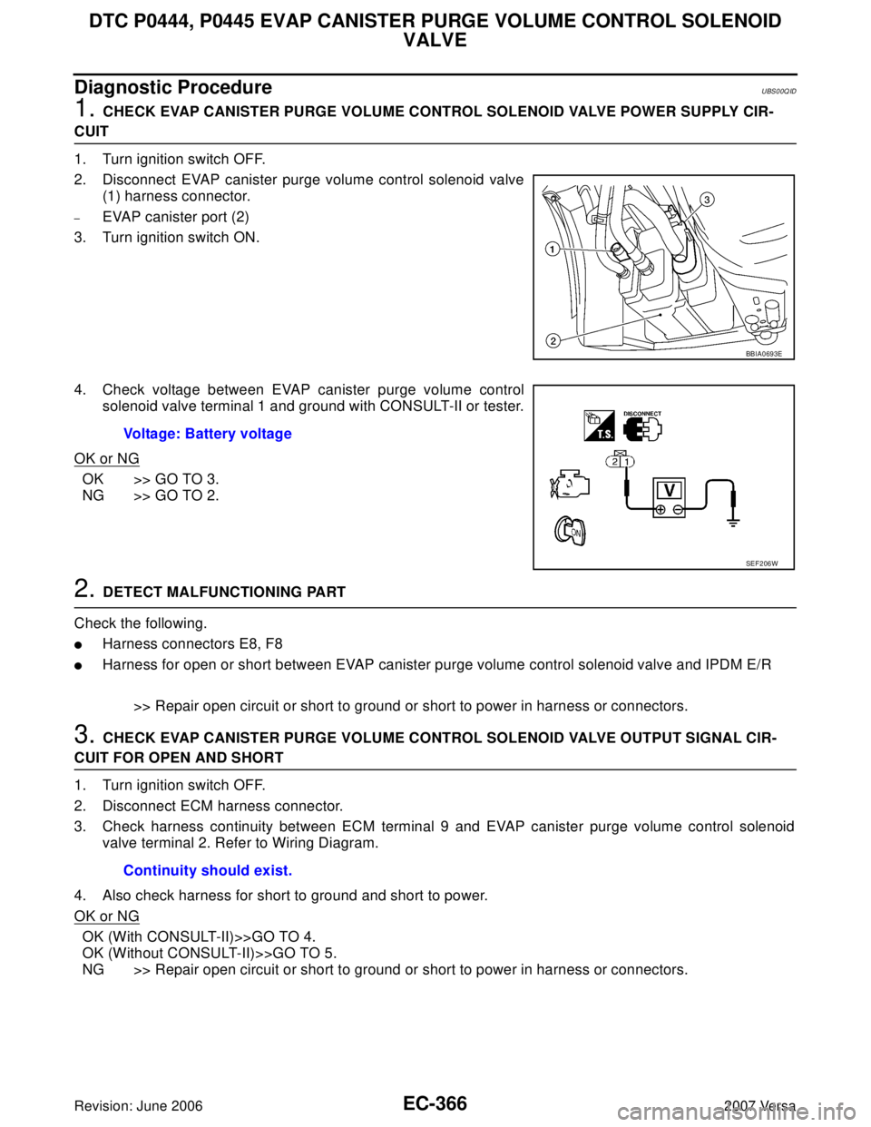
2. Disconnect EVAP canister purge volume control solenoid valve
(1) harness connector.
–EVAP canister port (2)
3. Turn ignition switch ON.
4. Check voltage between EVAP canister purge volume control
solenoid valve terminal 1 and ground with CONSULT-II or tester.
OK or NG
OK >> GO TO 3.
NG >> GO TO 2.
2. DETECT MALFUNCTIONING PART
Check the following.
�Harness connectors E8, F8
�Harness for open or short between EVAP canister purge volume control solenoid valve and IPDM E/R
>> Repair open circuit or short to ground or short to power in harness or connectors.
3. CHECK EVAP CANISTER PURGE VOLUME CONTROL SOLENOID VALVE OUTPUT SIGNAL CIR-
CUIT FOR OPEN AND SHORT
1. Turn ignition switch OFF.
2. Disconnect ECM harness connector.
3. Check harness continuity between ECM terminal 9 and EVAP canister purge volume control solenoid
valve terminal 2. Refer to Wiring Diagram.
4. Also check harness for short to ground and short to power.
OK or NG
OK (With CONSULT-II)>>GO TO 4.
OK (Without CONSULT-II)>>GO TO 5.
NG >> Repair open circuit or short to ground or short to power in harness or connectors.
BBIA0693E
Voltage: Battery voltage
SEF 2 06 W
Continuity should exist.
Page 1540 of 2896
DTC P0447 EVAP CANISTER VENT CONTROL VALVE
EC-371
C
D
E
F
G
H
I
J
K
L
MA
EC
Revision: June 20062007 Versa
Wiring DiagramUBS00QIK
BBWA2641E
Page 1542 of 2896

DTC P0447 EVAP CANISTER VENT CONTROL VALVE
EC-373
C
D
E
F
G
H
I
J
K
L
MA
EC
Revision: June 20062007 Versa
3. CHECK EVAP CANISTER VENT CONTROL VALVE POWER SUPPLY CIRCUIT
1. Turn ignition switch OFF.
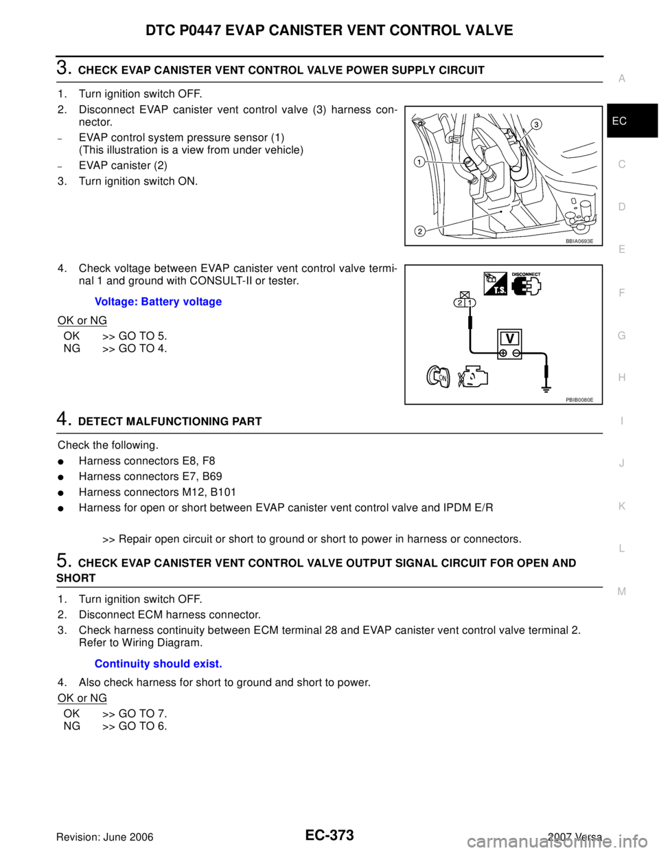
2. Disconnect EVAP canister vent control valve (3) harness con-
nector.
–EVAP control system pressure sensor (1)
(This illustration is a view from under vehicle)
–EVAP canister (2)
3. Turn ignition switch ON.
4. Check voltage between EVAP canister vent control valve termi-
nal 1 and ground with CONSULT-II or tester.
OK or NG
OK >> GO TO 5.
NG >> GO TO 4.
4. DETECT MALFUNCTIONING PART
Check the following.
�Harness connectors E8, F8
�Harness connectors E7, B69
�Harness connectors M12, B101
�Harness for open or short between EVAP canister vent control valve and IPDM E/R
>> Repair open circuit or short to ground or short to power in harness or connectors.
5. CHECK EVAP CANISTER VENT CONTROL VALVE OUTPUT SIGNAL CIRCUIT FOR OPEN AND
SHORT
1. Turn ignition switch OFF.
2. Disconnect ECM harness connector.
3. Check harness continuity between ECM terminal 28 and EVAP canister vent control valve terminal 2.
Refer to Wiring Diagram.
4. Also check harness for short to ground and short to power.
OK or NG
OK >> GO TO 7.
NG >> GO TO 6.
BBIA0693E
Voltage: Battery voltage
PBIB0080E
Continuity should exist.
Page 1547 of 2896
EC-378Revision: June 2006
DTC P0448 EVAP CANISTER VENT CONTROL VALVE
2007 Versa
Wiring DiagramUBS00QIR
BBWA2641E
Page 1553 of 2896

EC-384Revision: June 2006
DTC P0451 EVAP CONTROL SYSTEM PRESSURE SENSOR
2007 Versa
2. CHECK EVPA CONTROL SYSTEM PRESSURE SENSOR CONNECTOR FOR WATER
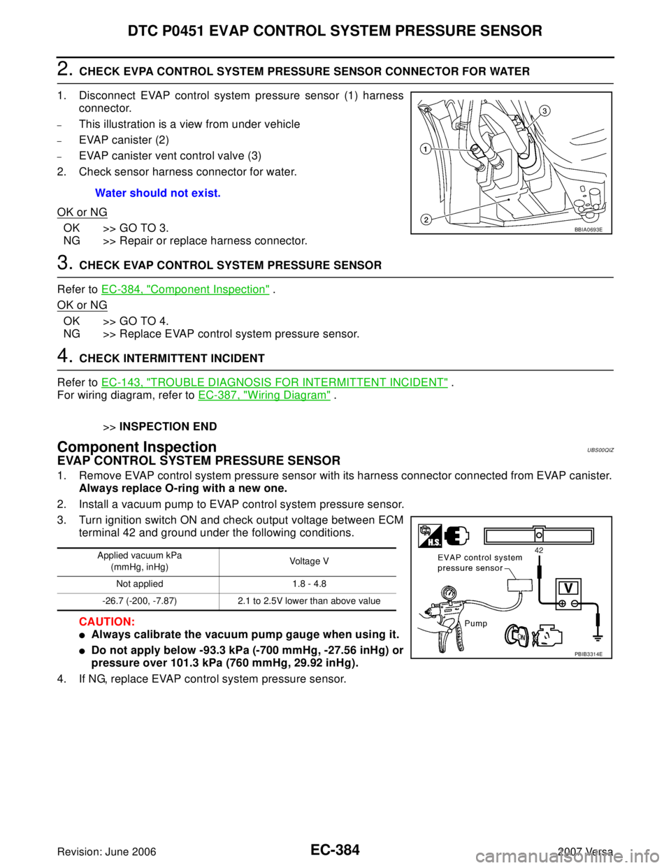
1. Disconnect EVAP control system pressure sensor (1) harness
connector.
–This illustration is a view from under vehicle
–EVAP canister (2)
–EVAP canister vent control valve (3)
2. Check sensor harness connector for water.
OK or NG
OK >> GO TO 3.
NG >> Repair or replace harness connector.
3. CHECK EVAP CONTROL SYSTEM PRESSURE SENSOR
Refer to EC-384, "
Component Inspection" .
OK or NG
OK >> GO TO 4.
NG >> Replace EVAP control system pressure sensor.
4. CHECK INTERMITTENT INCIDENT
Refer to EC-143, "
TROUBLE DIAGNOSIS FOR INTERMITTENT INCIDENT" .
For wiring diagram, refer to EC-387, "
Wiring Diagram" .
>>INSPECTION END
Component InspectionUBS00QIZ
EVAP CONTROL SYSTEM PRESSURE SENSOR
1. Remove EVAP control system pressure sensor with its harness connector connected from EVAP canister.
Always replace O-ring with a new one.
2. Install a vacuum pump to EVAP control system pressure sensor.
3. Turn ignition switch ON and check output voltage between ECM
terminal 42 and ground under the following conditions.
CAUTION:
�Always calibrate the vacuum pump gauge when using it.
�Do not apply below -93.3 kPa (-700 mmHg, -27.56 inHg) or
pressure over 101.3 kPa (760 mmHg, 29.92 inHg).
4. If NG, replace EVAP control system pressure sensor.Water should not exist.
BBIA0693E
Applied vacuum kPa
(mmHg, inHg)Voltage V
Not applied 1.8 - 4.8
-26.7 (-200, -7.87) 2.1 to 2.5V lower than above value
PBIB3314E
Page 1556 of 2896
DTC P0452 EVAP CONTROL SYSTEM PRESSURE SENSOR
EC-387
C
D
E
F
G
H
I
J
K
L
MA
EC
Revision: June 20062007 Versa
Wiring DiagramUBS00QJ4
BBWA2642E