Page 1545 of 2896
EC-376Revision: June 2006
DTC P0448 EVAP CANISTER VENT CONTROL VALVE
2007 Versa
DTC P0448 EVAP CANISTER VENT CONTROL VALVEPFP:16935
Component DescriptionUBS00QIN
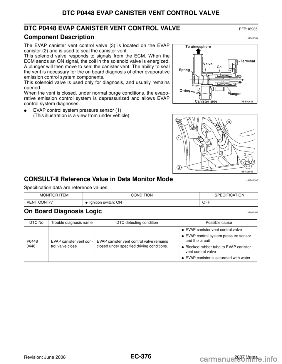
The EVAP canister vent control valve (3) is located on the EVAP
canister (2) and is used to seal the canister vent.
This solenoid valve responds to signals from the ECM. When the
ECM sends an ON signal, the coil in the solenoid valve is energized.
A plunger will then move to seal the canister vent. The ability to seal
the vent is necessary for the on board diagnosis of other evaporative
emission control system components.
This solenoid valve is used only for diagnosis, and usually remains
opened.
When the vent is closed, under normal purge conditions, the evapo-
rative emission control system is depressurized and allows EVAP
control system diagnoses.
�EVAP control system pressure sensor (1)
(This illustration is a view from under vehicle)
CONSULT-II Reference Value in Data Monitor ModeUBS00QIO
Specification data are reference values.
On Board Diagnosis LogicUBS00QIP
PBIB1263E
BBIA0693E
MONITOR ITEM CONDITION SPECIFICATION
VENT CONT/V
�Ignition switch: ON OFF
DTC No. Trouble diagnosis name DTC detecting condition Possible cause
P0448
0448EVAP canister vent con-
trol valve closeEVAP canister vent control valve remains
closed under specified driving conditions.
�EVAP canister vent control valve
�EVAP control system pressure sensor
and the circuit
�Blocked rubber tube to EVAP canister
vent control valve
�EVAP canister is saturated with water
Page 1614 of 2896
DTC P1217 ENGINE OVER TEMPERATURE
EC-445
C
D
E
F
G
H
I
J
K
L
MA
EC
Revision: June 20062007 Versa
On Board Diagnosis LogicUBS00QKV
If the cooling fan or another component in the cooling system malfunctions, engine coolant temperature will
rise. When the engine coolant temperature reaches an abnormally high temperature condition, a malfunction
is indicated.
This self-diagnosis has the one trip detection logic.
CAUTION:
When a malfunction is indicated, be sure to replace the coolant. Refer to CO-8, "
Changing Engine
Coolant" . Also, replace the engine oil. Refer to LU-6, "Changing Engine Oil" .
1. Fill radiator with coolant up to specified level with a filling speed of 2 liters per minute. Be sure to
use coolant with the proper mixture ratio. Refer to MA-12, "
Anti-freeze Coolant Mixture Ratio" .
2. After refilling coolant, run engine to ensure that no water-flow noise is emitted.
Overall Function CheckUBS00QKW
Use this procedure to check the overall function of the cooling fan. During this check, a DTC might not be con-
firmed.
WA RN ING:
Never remove the radiator cap when the engine is hot. Serious burns could be caused by high pres-
sure fluid escaping from the reservoir tank or the radiator.
Wrap a thick cloth around cap. Carefully remove the cap by turning it a quarter turn to allow built-up
pressure to escape. Then turn the cap all the way off.
WITH CONSULT-II
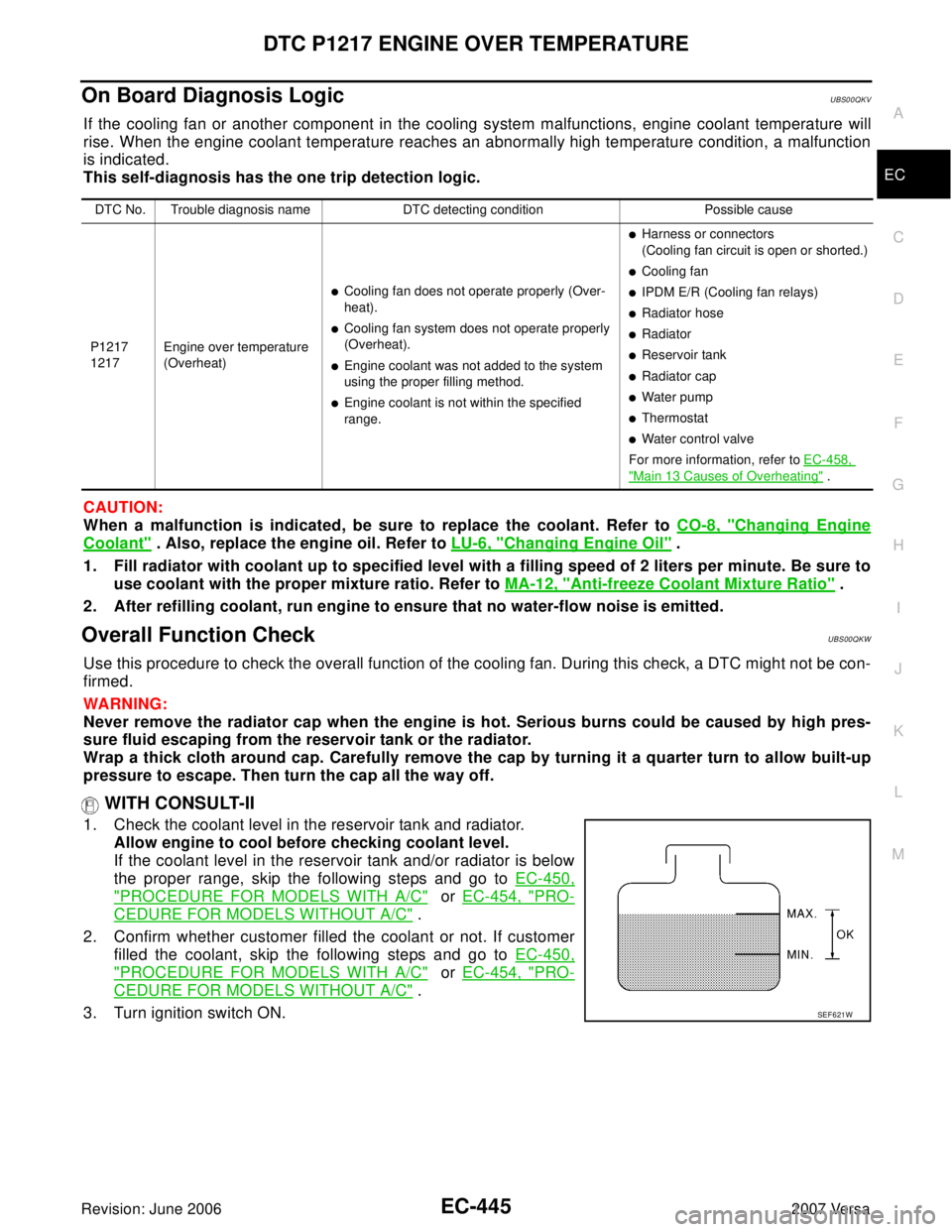
1. Check the coolant level in the reservoir tank and radiator.
Allow engine to cool before checking coolant level.
If the coolant level in the reservoir tank and/or radiator is below
the proper range, skip the following steps and go to EC-450,
"PROCEDURE FOR MODELS WITH A/C" or EC-454, "PRO-
CEDURE FOR MODELS WITHOUT A/C" .
2. Confirm whether customer filled the coolant or not. If customer
filled the coolant, skip the following steps and go to EC-450,
"PROCEDURE FOR MODELS WITH A/C" or EC-454, "PRO-
CEDURE FOR MODELS WITHOUT A/C" .
3. Turn ignition switch ON.
DTC No. Trouble diagnosis name DTC detecting condition Possible cause
P1217
1217Engine over temperature
(Overheat)
�Cooling fan does not operate properly (Over-
heat).
�Cooling fan system does not operate properly
(Overheat).
�Engine coolant was not added to the system
using the proper filling method.
�Engine coolant is not within the specified
range.
�Harness or connectors
(Cooling fan circuit is open or shorted.)
�Cooling fan
�IPDM E/R (Cooling fan relays)
�Radiator hose
�Radiator
�Reservoir tank
�Radiator cap
�Water pump
�Thermostat
�Water control valve
For more information, refer to EC-458,
"Main 13 Causes of Overheating" .
SEF 6 21 W
Page 1733 of 2896
EC-564Revision: June 2006
FUEL INJECTOR
2007 Versa
FUEL INJECTORPFP:16600
Component DescriptionUBS00PTO
The fuel injector is a small, precise solenoid valve. When the ECM
supplies a ground to the fuel injector circuit, the coil in the fuel injec-
tor is energized. The energized coil pulls the ball valve back and
allows fuel to flow through the fuel injector into the intake manifold.
The amount of fuel injected depends upon the injection pulse dura-
tion. Pulse duration is the length of time the fuel injector remains
open. The ECM controls the injection pulse duration based on
engine fuel needs.
CONSULT-II Reference Value in Data Monitor ModeUBS00PTP
Specification data are reference values.
PBIA9664J
MONITOR ITEM CONDITION SPECIFICATION
B/FUEL SCHDL See EC-133, "
TROUBLE DIAGNOSIS - SPECIFICATION VALUE" .
INJ PULSE-B1
�Engine: After warming up
�Air conditioner switch: OFF
�Shift lever: P or N (A/T, CVT),
Neutral (M/T)
�No loadIdle 2.0 - 3.0 msec
2,000 rpm 1.9 - 2.9 msec
Page 1745 of 2896
EC-576Revision: June 2006
IGNITION SIGNAL
2007 Versa
IGNITION SIGNALPFP:22448
Component DescriptionUBS00PU0
IGNITION COIL & POWER TRANSISTOR
The ignition signal from the ECM is sent to and amplified by the
power transistor. The power transistor turns ON and OFF the ignition
coil (1) primary circuit. This ON/OFF operation induces the proper
high voltage in the coil secondary circuit.
PBIB3328E
Page 1750 of 2896
IGNITION SIGNAL
EC-581
C
D
E
F
G
H
I
J
K
L
MA
EC
Revision: June 20062007 Versa
3. CHECK OVERALL FUNCTION
Without CONSULT-II
1. Let engine idle.
2. Read the voltage signal between ECM terminals 17, 18, 21, 22
and ground with an oscilloscope.
3. Verify that the oscilloscope screen shows the signal wave as
shown below.
NOTE:
The pulse cycle changes depending on rpm at idle.
OK or NG
OK >>INSPECTION END
NG >> GO TO 10.
4. CHECK IGNITION COIL POWER SUPPLY CIRCUIT-I
1. Turn ignition switch OFF, wait at least 10 seconds and then turn ON.
2. Check voltage between ECM terminal 105 and ground with
CONSULT-II or tester.
OK or NG
OK >> GO TO 5.
NG >> Go to EC-144, "
POWER SUPPLY AND GROUND CIR-
CUIT" .
PBIA9567J
PBIA9265J
Voltage: Battery voltage
PBIA9575J
Page 1751 of 2896
EC-582Revision: June 2006
IGNITION SIGNAL
2007 Versa
5. CHECK IGNITION COIL POWER SUPPLY CIRCUIT-II
1. Turn ignition switch OFF.
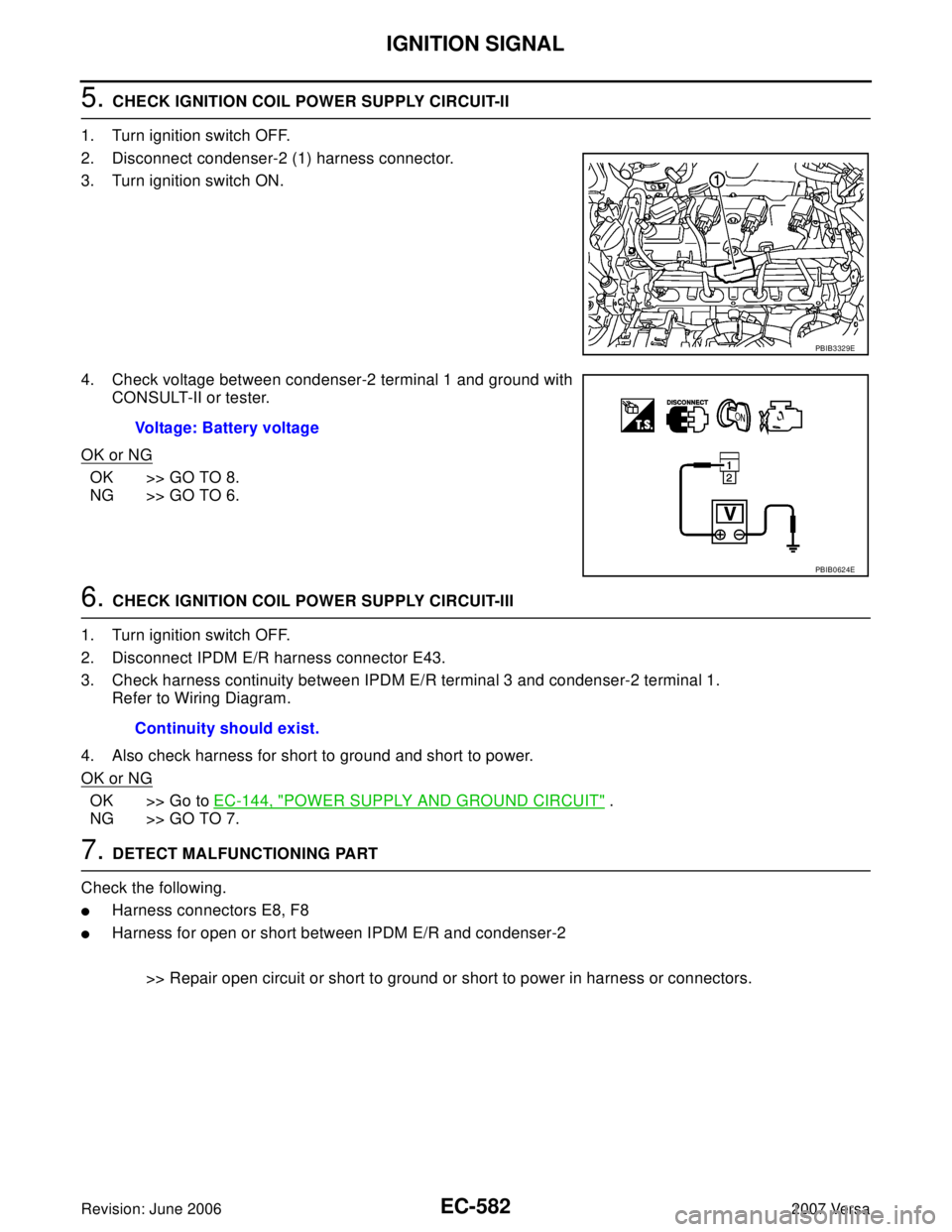
2. Disconnect condenser-2 (1) harness connector.
3. Turn ignition switch ON.
4. Check voltage between condenser-2 terminal 1 and ground with
CONSULT-II or tester.
OK or NG
OK >> GO TO 8.
NG >> GO TO 6.
6. CHECK IGNITION COIL POWER SUPPLY CIRCUIT-III
1. Turn ignition switch OFF.
2. Disconnect IPDM E/R harness connector E43.
3. Check harness continuity between IPDM E/R terminal 3 and condenser-2 terminal 1.
Refer to Wiring Diagram.
4. Also check harness for short to ground and short to power.
OK or NG
OK >> Go to EC-144, "POWER SUPPLY AND GROUND CIRCUIT" .
NG >> GO TO 7.
7. DETECT MALFUNCTIONING PART
Check the following.
�Harness connectors E8, F8
�Harness for open or short between IPDM E/R and condenser-2
>> Repair open circuit or short to ground or short to power in harness or connectors.
PBIB3329E
Voltage: Battery voltage
PBIB0624E
Continuity should exist.
Page 1752 of 2896
IGNITION SIGNAL
EC-583
C
D
E
F
G
H
I
J
K
L
MA
EC
Revision: June 20062007 Versa
8. CHECK CONDENSER-2 GROUND CIRCUIT FOR OPEN AND SHORT
1. Turn ignition switch OFF.
2. Check harness continuity between condenser-2 terminal 2 and ground.
Refer to Wiring Diagram.
3. Also check harness for short to power.
OK or NG
OK >> GO TO 9.
NG >> Repair open circuit or short to power in harness or connectors.
9. CHECK CONDENSER-2
Refer to EC-584, "
Component Inspection"
OK or NG
OK >> GO TO 10.
NG >> Replace condenser-2.
10. CHECK IGNITION COIL POWER SUPPLY CIRCUIT-IV
1. Turn ignition switch OFF.
2. Reconnect all harness connectors disconnected.
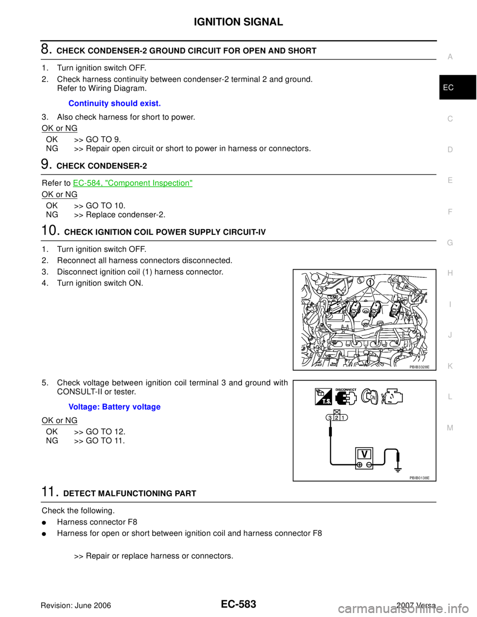
3. Disconnect ignition coil (1) harness connector.
4. Turn ignition switch ON.
5. Check voltage between ignition coil terminal 3 and ground with
CONSULT-II or tester.
OK or NG
OK >> GO TO 12.
NG >> GO TO 11.
11 . DETECT MALFUNCTIONING PART
Check the following.
�Harness connector F8
�Harness for open or short between ignition coil and harness connector F8
>> Repair or replace harness or connectors. Continuity should exist.
PBIB3328E
Voltage: Battery voltage
PBIB0138E
Page 1753 of 2896
EC-584Revision: June 2006
IGNITION SIGNAL
2007 Versa
12. CHECK IGNITION COIL GROUND CIRCUIT FOR OPEN AND SHORT
1. Turn ignition switch OFF.
2. Check harness continuity between ignition coil terminal 2 and ground.
Refer to Wiring Diagram.
3. Also check harness for short to power.
OK or NG
OK >> GO TO 13.
NG >> Repair open circuit or short to power in harness or connectors.
13. CHECK IGNITION COIL OUTPUT SIGNAL CIRCUIT FOR OPEN AND SHORT
1. Disconnect ECM harness connector.
2. Check harness continuity between ECM terminals 17, 18, 21, 22 and ignition coil terminal 1.
Refer to Wiring Diagram.
3. Also check harness for short to ground and short to power.
OK or NG
OK >> GO TO 14.
NG >> Repair open circuit or short to ground or short to power in harness or connectors.
14. CHECK IGNITION COIL WITH POWER TRANSISTOR
Refer to EC-584, "
Component Inspection" .
OK or NG
OK >> GO TO 15.
NG >> Replace ignition coil with power transistor.
15. CHECK INTERMITTENT INCIDENT
Refer to EC-143, "
TROUBLE DIAGNOSIS FOR INTERMITTENT INCIDENT" .
>>INSPECTION END
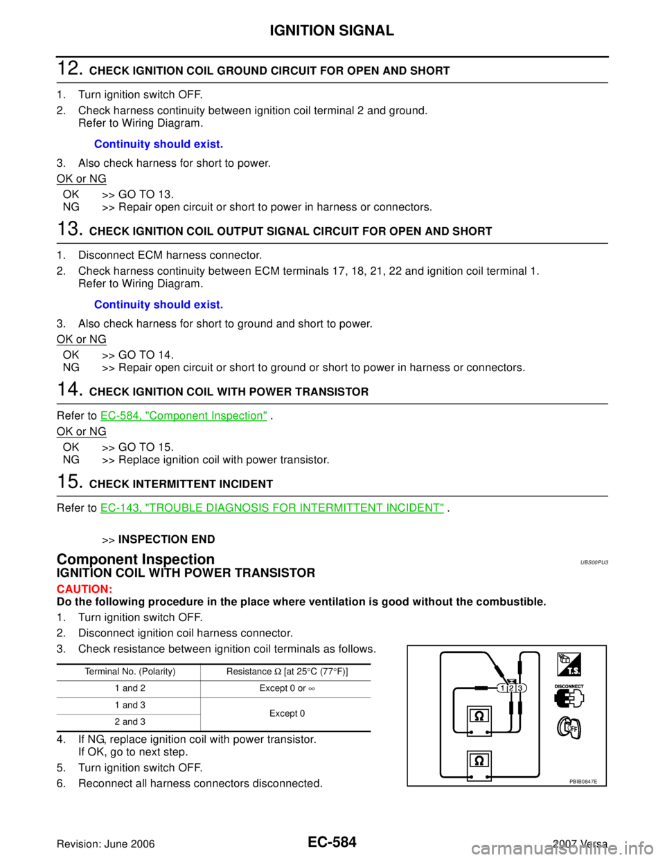
Component InspectionUBS00PU3
IGNITION COIL WITH POWER TRANSISTOR
CAUTION:
Do the following procedure in the place where ventilation is good without the combustible.
1. Turn ignition switch OFF.
2. Disconnect ignition coil harness connector.
3. Check resistance between ignition coil terminals as follows.
4. If NG, replace ignition coil with power transistor.
If OK, go to next step.
5. Turn ignition switch OFF.
6. Reconnect all harness connectors disconnected.Continuity should exist.
Continuity should exist.
Terminal No. (Polarity) Resistance Ω [at 25°C (77°F)]
1 and 2 Except 0 or ∞
1 and 3
Except 0
2 and 3
PBIB0847E