Page 1392 of 2896
DTC P0130 A/F SENSOR 1
EC-223
C
D
E
F
G
H
I
J
K
L
MA
EC
Revision: June 20062007 Versa
Wiring DiagramUBS00QEQ
BBWA2631E
Page 1394 of 2896

DTC P0130 A/F SENSOR 1
EC-225
C
D
E
F
G
H
I
J
K
L
MA
EC
Revision: June 20062007 Versa
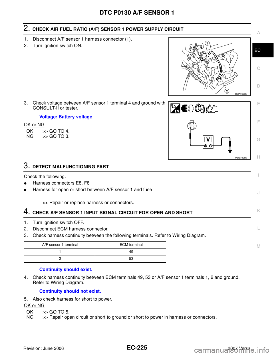
2. CHECK AIR FUEL RATIO (A/F) SENSOR 1 POWER SUPPLY CIRCUIT
1. Disconnect A/F sensor 1 harness connector (1).
2. Turn ignition switch ON.
3. Check voltage between A/F sensor 1 terminal 4 and ground with
CONSULT-II or tester.
OK or NG
OK >> GO TO 4.
NG >> GO TO 3.
3. DETECT MALFUNCTIONING PART
Check the following.
�Harness connectors E8, F8
�Harness for open or short between A/F sensor 1 and fuse
>> Repair or replace harness or connectors.
4. CHECK A/F SENSOR 1 INPUT SIGNAL CIRCUIT FOR OPEN AND SHORT
1. Turn ignition switch OFF.
2. Disconnect ECM harness connector.
3. Check harness continuity between the following terminals. Refer to Wiring Diagram.
4. Check harness continuity between ECM terminals 49, 53 or A/F sensor 1 terminals 1, 2 and ground.
Refer to Wiring Diagram.
5. Also check harness for short to power.
OK or NG
OK >> GO TO 5.
NG >> Repair open circuit or short to ground or short to power in harness or connectors.
BBIA0699E
Voltage: Battery voltage
PBIB3308E
A/F sensor 1 terminal ECM terminal
149
253
Continuity should exist.
Continuity should not exist.
Page 1398 of 2896
DTC P0131 A/F SENSOR 1
EC-229
C
D
E
F
G
H
I
J
K
L
MA
EC
Revision: June 20062007 Versa
Wiring DiagramUBS00QEX
BBWA2631E
Page 1400 of 2896

DTC P0131 A/F SENSOR 1
EC-231
C
D
E
F
G
H
I
J
K
L
MA
EC
Revision: June 20062007 Versa
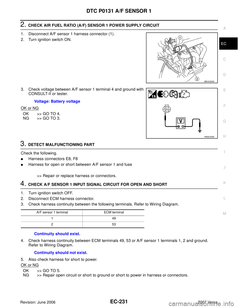
2. CHECK AIR FUEL RATIO (A/F) SENSOR 1 POWER SUPPLY CIRCUIT
1. Disconnect A/F sensor 1 harness connector (1).
2. Turn ignition switch ON.
3. Check voltage between A/F sensor 1 terminal 4 and ground with
CONSULT-II or tester.
OK or NG
OK >> GO TO 4.
NG >> GO TO 3.
3. DETECT MALFUNCTIONING PART
Check the following.
�Harness connectors E8, F8
�Harness for open or short between A/F sensor 1 and fuse
>> Repair or replace harness or connectors.
4. CHECK A/F SENSOR 1 INPUT SIGNAL CIRCUIT FOR OPEN AND SHORT
1. Turn ignition switch OFF.
2. Disconnect ECM harness connector.
3. Check harness continuity between the following terminals. Refer to Wiring Diagram.
4. Check harness continuity between ECM terminals 49, 53 or A/F sensor 1 terminals 1, 2 and ground.
Refer to Wiring Diagram.
5. Also check harness for short to power.
OK or NG
OK >> GO TO 5.
NG >> Repair open circuit or short to ground or short to power in harness or connectors.
BBIA0699E
Voltage: Battery voltage
PBIB3308E
A/F sensor 1 terminal ECM terminal
149
253
Continuity should exist.
Continuity should not exist.
Page 1404 of 2896
DTC P0132 A/F SENSOR 1
EC-235
C
D
E
F
G
H
I
J
K
L
MA
EC
Revision: June 20062007 Versa
Wiring DiagramUBS00QF4
BBWA2631E
Page 1406 of 2896

DTC P0132 A/F SENSOR 1
EC-237
C
D
E
F
G
H
I
J
K
L
MA
EC
Revision: June 20062007 Versa
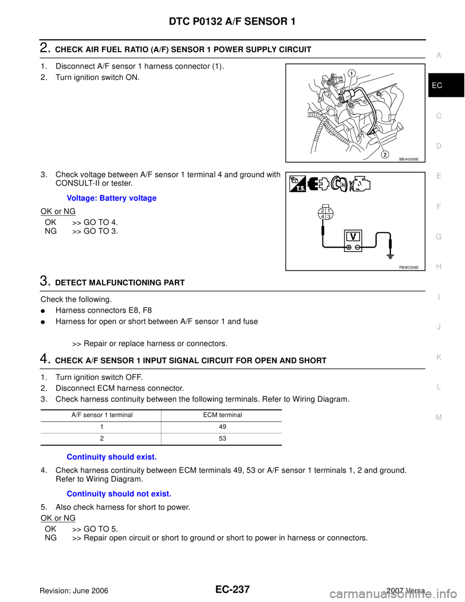
2. CHECK AIR FUEL RATIO (A/F) SENSOR 1 POWER SUPPLY CIRCUIT
1. Disconnect A/F sensor 1 harness connector (1).
2. Turn ignition switch ON.
3. Check voltage between A/F sensor 1 terminal 4 and ground with
CONSULT-II or tester.
OK or NG
OK >> GO TO 4.
NG >> GO TO 3.
3. DETECT MALFUNCTIONING PART
Check the following.
�Harness connectors E8, F8
�Harness for open or short between A/F sensor 1 and fuse
>> Repair or replace harness or connectors.
4. CHECK A/F SENSOR 1 INPUT SIGNAL CIRCUIT FOR OPEN AND SHORT
1. Turn ignition switch OFF.
2. Disconnect ECM harness connector.
3. Check harness continuity between the following terminals. Refer to Wiring Diagram.
4. Check harness continuity between ECM terminals 49, 53 or A/F sensor 1 terminals 1, 2 and ground.
Refer to Wiring Diagram.
5. Also check harness for short to power.
OK or NG
OK >> GO TO 5.
NG >> Repair open circuit or short to ground or short to power in harness or connectors.
BBIA0699E
Voltage: Battery voltage
PBIB3308E
A/F sensor 1 terminal ECM terminal
149
253
Continuity should exist.
Continuity should not exist.
Page 1411 of 2896
EC-242Revision: June 2006
DTC P0133 A/F SENSOR 1
2007 Versa
Wiring DiagramUBS00QFB
BBWA2631E
Page 1415 of 2896

EC-246Revision: June 2006
DTC P0133 A/F SENSOR 1
2007 Versa
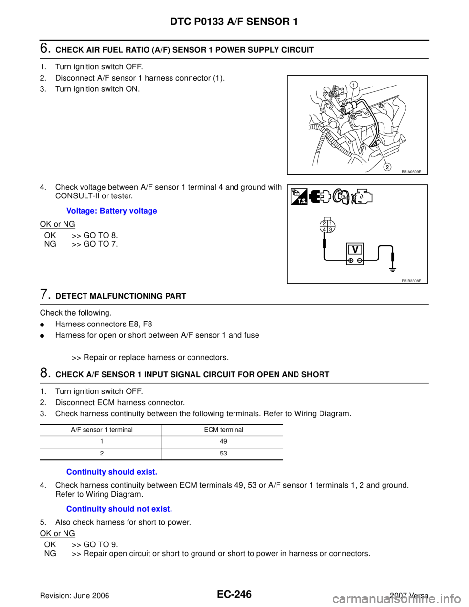
6. CHECK AIR FUEL RATIO (A/F) SENSOR 1 POWER SUPPLY CIRCUIT
1. Turn ignition switch OFF.
2. Disconnect A/F sensor 1 harness connector (1).
3. Turn ignition switch ON.
4. Check voltage between A/F sensor 1 terminal 4 and ground with
CONSULT-II or tester.
OK or NG
OK >> GO TO 8.
NG >> GO TO 7.
7. DETECT MALFUNCTIONING PART
Check the following.
�Harness connectors E8, F8
�Harness for open or short between A/F sensor 1 and fuse
>> Repair or replace harness or connectors.
8. CHECK A/F SENSOR 1 INPUT SIGNAL CIRCUIT FOR OPEN AND SHORT
1. Turn ignition switch OFF.
2. Disconnect ECM harness connector.
3. Check harness continuity between the following terminals. Refer to Wiring Diagram.
4. Check harness continuity between ECM terminals 49, 53 or A/F sensor 1 terminals 1, 2 and ground.
Refer to Wiring Diagram.
5. Also check harness for short to power.
OK or NG
OK >> GO TO 9.
NG >> Repair open circuit or short to ground or short to power in harness or connectors.
BBIA0699E
Voltage: Battery voltage
PBIB3308E
A/F sensor 1 terminal ECM terminal
149
253
Continuity should exist.
Continuity should not exist.