Page 1408 of 2896
 sensor 1 is a planar one-ce")
DTC P0133 A/F SENSOR 1
EC-239
C
D
E
F
G
H
I
J
K
L
MA
EC
Revision: June 20062007 Versa
DTC P0133 A/F SENSOR 1PFP:22693
Component DescriptionUBS00QF7
The air fuel ratio (A/F) sensor 1 is a planar one-cell limit current sen-
sor. The sensor element of the A/F sensor 1 is composed an elec-
trode layer, which transports ions. It has a heater in the element.
The sensor is capable of precise measurement = 1, but also in the
lean and rich range. Together with its control electronics, the sensor
outputs a clear, continuous signal throughout a wide range.
The exhaust gas components diffuse through the diffusion layer at
the sensor cell. An electrode layer is applied voltage, and this current
relative oxygen density in lean. Also this current relative hydrocar-
bon density in rich.
Therefore, the A/F sensor 1 is able to indicate air fuel ratio by this
electrode layer of current. In addition, a heater is integrated in the
sensor to ensure the required operating temperature of about 800°C
(1,472°F).
CONSULT-II Reference Value in Data Monitor ModeUBS00QF8
Specification data are reference values.
On Board Diagnosis LogicUBS00QF9
To judge the malfunction of air fuel ratio (A/F) sensor 1, this diagnosis measures response time of the A/F sig-
nal computed by ECM from the air fuel ratio (A/F) sensor 1 signal. The time is compensated by engine operat-
ing (speed and load), fuel feedback control constant, and the air fuel ratio (A/F) sensor 1 temperature index.
Judgment is based on whether the compensated time (the A/F sensor 1 signal cycling time index) is inordi-
nately long or not.
PBIB3353E
PBIB3354E
MONITOR ITEM CONDITION SPECIFICATION
A/F SEN1 (B1)
�Engine: After warming upMaintaining engine speed at
2,000 rpmFluctuates around 2.2V
DTC No.Trouble diag-
nosis nameDTC detecting condition Possible Cause
P0133
0133Air fuel ratio
(A/F) sensor 1
circuit slow
responseThe response of the A/F signal computed by ECM
from A/F sensor 1 signal takes more than the specified
time.
�Harness or connectors
[Air fuel ratio (A/F) sensor circuit is open
or shorted.]
�Air fuel ratio (A/F) sensor 1
�Air fuel ratio (A/F) sensor heater 1
�Fuel pressure
�Fuel injector
�Intake air leaks
�Exhaust gas leaks
�PCV
�Mass air flow sensor
Page 1410 of 2896

DTC P0133 A/F SENSOR 1
EC-241
C
D
E
F
G
H
I
J
K
L
MA
EC
Revision: June 20062007 Versa
WITH GST
1. Start engine and warm it up to normal operating temperature.
2. Select Service $01 with GST.
3. Calculate the total value of “Short term fuel trim” and “Long term fuel trim” indications.
Make sure that the total percentage should be within ±15%.
If OK, go to the following step.
If NG, check the following.
�Intake air leaks
�Exhaust gas leaks
�Incorrect fuel pressure
�Lack of fuel
�Fuel injector
�Incorrect PCV hose connection
�PCV valve
�Mass air flow sensor
4. Turn ignition switch OFF and wait at least 10 seconds.
5. Start engine and keep the engine speed between 3,500 and 4,000 rpm for at least 1minute under no load.
6. Let engine idle for 1 minute.
7. Increase the engine speed up to 4,000 to 5,000 rpm and keep it for 10 seconds.
8. Fully release accelerator pedal and then let engine idle for about 1 minute.
9. Select Service $07 with GST.
If 1st trip DTC is detected, go to EC-243, "
Diagnostic Procedure" .
Page 1412 of 2896

DTC P0133 A/F SENSOR 1
EC-243
C
D
E
F
G
H
I
J
K
L
MA
EC
Revision: June 20062007 Versa
Specification data are reference values and are measured between each terminal and ground.
Pulse signal is measured by CONSULT-II.
CAUTION:
Do not use ECM ground terminals when measuring input/output voltage. Doing so may result in dam-
age to the ECM's transistor. Use a ground other than ECM terminals, such as the ground.
: Average voltage for pulse signal (Actual pulse signal can be confirmed by oscilloscope.)
Diagnostic ProcedureUBS00QFC
1. CHECK GROUND CONNECTIONS
1. Turn ignition switch OFF.
2. Loosen and retighten engine screw on the body.
Refer to EC-150, "
Ground Inspection" .
OK or NG
OK >> GO TO 2.
NG >> Repair or replace ground connections.
TERMI-
NAL
NO.WIRE
COLORITEM CONDITION DATA (DC Voltage)
3 G A/F sensor 1 heater[Engine is running]
�Warm-up condition
�Idle speed
(More than 140 seconds after starting
engine)Approximately 2.9 - 8.8V
49 W A/F sensor 1[Engine is running]
�Warm-up condition
�Engine speed: 2,000 rpmApproximately 1.8V
Output voltage varies with air fuel
ratio.
53 B A/F sensor 1[Ignition switch: ON]Approximately 2.2V
PBIA8148J
:Vehicle front
1. Body ground E24 2. Engine ground F9 3. Engine ground F16
4. Body ground E15
BBIA0698E
Page 1413 of 2896
EC-244Revision: June 2006
DTC P0133 A/F SENSOR 1
2007 Versa
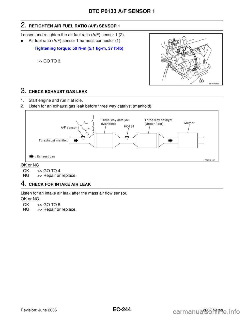
2. RETIGHTEN AIR FUEL RATIO (A/F) SENSOR 1
Loosen and retighten the air fuel ratio (A/F) sensor 1 (2).
�Air fuel ratio (A/F) sensor 1 harness connector (1)
>> GO TO 3.
3. CHECK EXHAUST GAS LEAK
1. Start engine and run it at idle.
2. Listen for an exhaust gas leak before three way catalyst (manifold).
OK or NG
OK >> GO TO 4.
NG >> Repair or replace.
4. CHECK FOR INTAKE AIR LEAK
Listen for an intake air leak after the mass air flow sensor.
OK or NG
OK >> GO TO 5.
NG >> Repair or replace.Tightening torque: 50 N-m (5.1 kg-m, 37 ft-lb)
BBIA0699E
PBIB1216E
Page 1414 of 2896

DTC P0133 A/F SENSOR 1
EC-245
C
D
E
F
G
H
I
J
K
L
MA
EC
Revision: June 20062007 Versa
5. CLEAR THE SELF-LEARNING DATA
With CONSULT-II
1. Start engine and warm it up to normal operating temperature.
2. Select “SELF-LEARNING CONT” in “WORK SUPPORT” mode with CONSULT-II.
3. Clear the self-learning control coefficient by touching “CLEAR”
or “START”.
4. Run engine for at least 10 minutes at idle speed.
Is the 1st trip DTC P0171 or P0172 detected? Is it difficult to
start engine?
Without CONSULT-II
1. Start engine and warm it up to normal operating temperature.
2. Turn ignition switch OFF.
3. Disconnect mass air flow sensor (1) harness connector, and
restart and run engine for at least 5 seconds at idle speed.
4. Stop engine and reconnect mass air flow sensor harness con-
nector.
5. Make sure DTC P0102 is displayed.
6. Erase the DTC memory. Refer to EC-60, "
HOW TO ERASE
EMISSION-RELATED DIAGNOSTIC INFORMATION" .
7. Make sure DTC P0000 is displayed.
8. Run engine for at least 10 minutes at idle speed.
Is the 1st trip DTC P0171 or P0172 detected? Is it difficult to
start engine?
Ye s o r N o
Yes >> Perform trouble diagnosis for DTC P0171, P0172. Refer to EC-276, "DTC P0171 FUEL INJEC-
TION SYSTEM FUNCTION" or EC-284, "DTC P0172 FUEL INJECTION SYSTEM FUNCTION" .
No >> GO TO 6.
SEF 2 15 Z
BBIA0701E
Page 1415 of 2896
 SENSOR 1 POWER SUPPLY CIRCUIT
1. Turn ignition switch OFF.
2. Disconnect A/F sensor 1 harness connector (1).
3")
EC-246Revision: June 2006
DTC P0133 A/F SENSOR 1
2007 Versa
6. CHECK AIR FUEL RATIO (A/F) SENSOR 1 POWER SUPPLY CIRCUIT
1. Turn ignition switch OFF.
2. Disconnect A/F sensor 1 harness connector (1).
3. Turn ignition switch ON.
4. Check voltage between A/F sensor 1 terminal 4 and ground with
CONSULT-II or tester.
OK or NG
OK >> GO TO 8.
NG >> GO TO 7.
7. DETECT MALFUNCTIONING PART
Check the following.
�Harness connectors E8, F8
�Harness for open or short between A/F sensor 1 and fuse
>> Repair or replace harness or connectors.
8. CHECK A/F SENSOR 1 INPUT SIGNAL CIRCUIT FOR OPEN AND SHORT
1. Turn ignition switch OFF.
2. Disconnect ECM harness connector.
3. Check harness continuity between the following terminals. Refer to Wiring Diagram.
4. Check harness continuity between ECM terminals 49, 53 or A/F sensor 1 terminals 1, 2 and ground.
Refer to Wiring Diagram.
5. Also check harness for short to power.
OK or NG
OK >> GO TO 9.
NG >> Repair open circuit or short to ground or short to power in harness or connectors.
BBIA0699E
Voltage: Battery voltage
PBIB3308E
A/F sensor 1 terminal ECM terminal
149
253
Continuity should exist.
Continuity should not exist.
Page 1416 of 2896
 SENSOR 1 HEATER
Refer to EC-165, \"
Component Inspection\" .
OK or NG
OK >> GO TO 10.")
DTC P0133 A/F SENSOR 1
EC-247
C
D
E
F
G
H
I
J
K
L
MA
EC
Revision: June 20062007 Versa
9. CHECK AIR FUEL RATIO (A/F) SENSOR 1 HEATER
Refer to EC-165, "
Component Inspection" .
OK or NG
OK >> GO TO 10.
NG >> GO TO 13.
10. CHECK MASS AIR FLOW SENSOR
Refer to EC-185, "
Component Inspection" .
OK or NG
OK >> GO TO 11.
NG >> Replace mass air flow sensor.
11 . CHECK PCV VALVE
Refer to EC-44, "
Component Inspection" .
OK or NG
OK >> GO TO 12.
NG >> Repair or replace PCV valve.
12. CHECK INTERMITTENT INCIDENT
Perform EC-143, "
TROUBLE DIAGNOSIS FOR INTERMITTENT INCIDENT" .
OK or NG
OK >> GO TO 13.
NG >> Repair or replace.
13. REPLACE AIR FUEL RATIO (A/F) SENSOR 1
Replace air fuel ratio (A/F) sensor 1.
CAUTION:
�Discard any A/F sensor which has been dropped from a height of more than 0.5 m (19.7 in) onto a
hard surface such as a concrete floor; use a new one.
�Before installing new A/F sensor, clean exhaust system threads using Oxygen Sensor Thread
Cleaner tool J-43897-18 or J-43897-12 and approved anti-seize lubricant.
>>INSPECTION END
Removal and InstallationUBS00QFD
AIR FUEL RATIO SENSOR
Refer to EM-21, "EXHAUST MANIFOLD" .
Page 1417 of 2896
,
monitors the oxygen level i")
EC-248Revision: June 2006
DTC P0137 HO2S2
2007 Versa
DTC P0137 HO2S2PFP:226A0
Component DescriptionUBS00QFE
The heated oxygen sensor 2, after three way catalyst (manifold),
monitors the oxygen level in the exhaust gas.
Even if switching characteristics of the air fuel ratio (A/F) sensor 1
are shifted, the air/fuel ratio is controlled to stoichiometric, by the sig-
nal from the heated oxygen sensor 2.
This sensor is made of ceramic zirconia. The zirconia generates volt-
age from approximately 1V in richer conditions to 0V in leaner condi-
tions.
Under normal conditions the heated oxygen sensor 2 is not used for
engine control operation.
CONSULT-II Reference Value in Data Monitor ModeUBS00QFF
Specification data are reference values.
On Board Diagnosis LogicUBS00QFG
The heated oxygen sensor 2 has a much longer switching time
between rich and lean than the air fuel ratio (A/F) sensor 1. The oxy-
gen storage capacity before the three way catalyst (manifold) causes
the longer switching time. To judge the malfunctions of heated oxy-
gen sensor 2, ECM monitors whether the maximum voltage of the
sensor is sufficiently high during the various driving condition such
as fuel-cut.
SEF 3 27 R
MONITOR ITEM CONDITION SPECIFICATION
HO2S2 (B1)
�Revving engine from idle to 3,000 rpm quickly after the follow-
ing conditions are met.
–Engine: After warming up
–Keeping the engine speed between 3,500 and 4,000 rpm for 1
minute and at idle for 1 minute under no load0 - 0.3V ←→ Approx. 0.6 - 1.0V
HO2S2 MNTR (B1) LEAN ←→ RICH
SEF 2 59 VA
DTC No. Trouble diagnosis name DTC detecting condition Possible cause
P0137
0137Heated oxygen sensor 2 cir-
cuit low voltageThe maximum voltage from the sensor is
not reached to the specified voltage.
�Harness or connectors
(Heated oxygen sensor 2 circuit open or
shorted.)
�Heated oxygen sensor 2
�Fuel pressure
�Fuel injector
�Intake air leaks