Page 2563 of 2896
HARNESS
PG-47
C
D
E
F
G
H
I
J
L
MA
B
PG
Revision: June 20062007 Versa
ENGINE CONTROL HARNESS
LKIA0817E
Page 2564 of 2896

PG-48
HARNESS
Revision: June 20062007 Versa
B4 F1 B/3 : Generator E4 F39 — : Fusible link box (battery)
B5 F2 — : Generator E4 F40 — : Fusible link box (battery)
B5 F3 B/1 : A/C compressor E2 F41 GR/2 : Vehicle speed sensor
B4 F4 — : Generator F5 F45 GR/3 : Turbine revolution sensor
A4 F5 — : Generator ground E5 F46 GR/22 : CVT unit
E3 F6 GR/2 : Engine coolant temperature sensor E5 F47 B/3 : Powertrain revolution sensor (with A/T)
D2 F7 B/6 : Electric throttle control actuator E3 F48 B/3 : Secondary speed sensor (with M/T)
G4 F8 SMJ : To E8
B4 F9 — : Engine ground
G2 F10 GR/32 : ECM
G2 F11 BR/48 : ECM
D3 F12 GR/4 : Air fuel ratio (A/F) sensor 1
E2 F13 B/4 : Heated oxygen sensor 2
C4 F14 B/2 : Knock sensor
D3 F15 B/3 : Crankshaft position sensor (POS)
C4 F16 — : Engine ground
B4 F17 GR/2 : Fuel injector No. 1
C4 F18 GR/2 : Fuel injector No. 2
C4 F19 GR/2 : Fuel injector No. 3
D4 F20 GR/2 : Fuel injector No. 4
D4 F21 B/3 : Camshaft position sensor (PHASE)
C3 F22 GR/2: EVAP canister purge volume control
solenoid valve
B3 F23 GR/2: Intake valve timing control solenoid
valve
E5 F24 G/3: Park/neutral position (PNP) switch
(with M/T)
F5 F25 B/10: Park/neutral position (PNP) switch
(with A/T)
C3 F26 W/2 : Condenser-2
C5 F27 — : Starter motor
C5 F28 — : Starter motor
F5 F30 B/8 : Terminal cord assembly
F2 F31 B/6 : Mass air flow sensor
C5 F32 GR/1 : Oil pressure switch
F5 F33 GR/6 : To E19
C3 F34 GR/3: Ignition coil No. 1 (with power tran-
sistor)
C3 F35 GR/3: Ignition coil No. 2 (with power tran-
sistor)
C3 F36 GR/3: Ignition coil No. 3 (with power tran-
sistor)
C3 F37 GR/3: Ignition coil No. 4 (with power tran-
sistor)
E5 F38 BR/3 : Revolution sensor
Page 2577 of 2896

HARNESS
PG-61
C
D
E
F
G
H
I
J
L
MA
B
PG
Revision: June 20062007 Versa
Wiring Diagram Codes (Cell Codes)EKS00IW9
Use the chart below to find out what each wiring diagram code stands for.
Refer to the wiring diagram code in the alphabetical index to find the location (page number) of each wiring
diagram.
Code Section Wiring Diagram Name
ABS BRC Anti-lock Brake System
A/C,M MTC Manual Air Conditioner
APPS1 EC Accelerator Pedal Position Sensor
A/F EC Air Fuel Ratio Sensor 1
A/FH EC Air Fuel Ratio Sensor 1 Heater
APPS2 EC Accelerator Pedal Position Sensor
APPS3 EC Accelerator Pedal Position Sensor
ASC/BS EC ASCD Brake Switch
ASC/SW EC ASCD Steering Switch
ASCBOF EC ASCD Brake Switch
ASCIND EC ASCD Indicator
AT/IND DI A/T Indicator Lamp
AUDIO AV Audio
BACK/L LT Back-up Lamp
BA/FTS AT A/T Fluid Temperature Sensor and TCM Power Supply
BRK/SW EC Brake Switch
CAN AT CAN Communication Line
CAN CVT CAN Communication Line
CAN EC CAN Communication Line
CAN LAN CAN System
CHARGE SC Charging System
CHIME DI Warning Chime
COOL/F EC Cooling Fan Control
COMBSW LT Combination Switch
CVTIND DI CVT Indicator Lamp
D/LOCK BL Power Door Lock
DEF GW Rear Window Defogger
DTRL LT Headlamp - With Daytime Light System
ECTS EC Engine Coolant Temperature Sensor
ENGSS AT Engine Speed Signal
EPS STC Electronic Controlled Power Steering
ETC1 EC Electric Throttle Control Function
ETC2 EC Throttle Control Motor Relay
ETC3 EC Throttle Control Motor
F/FOG LT Front Fog Lamp
F/PUMP EC Fuel Pump
FTS AT A/T Fluid Temperature Sensor
FTS CVT CVT Fluid Temperature Sensor Circuit
FTTS EC Fuel Tank Temperature Sensor
FUEL EC Fuel Ignition System Function
HEATER MTC Heater System
H/LAMP LT Headlamp
H/PHON AV Hands Free Telephone
HORN WW Horn
HO2S2 EC Heated Oxygen Sensor 2
HO2S2H EC Heated Oxygen Sensor 2 Heater
IATS EC Intake Air Temperature Sensor
Page 2580 of 2896
PG-64
ELECTRICAL UNITS LOCATION
Revision: June 20062007 Versa
ELECTRICAL UNITS LOCATIONPFP:25230
Electrical Units Location EKS00I5Z
ENGINE COMPARTMENT
LKIA0826E
Page 2600 of 2896

PS-6
STEERING WHEEL
Revision: June 20062007 Versa
STEERING WHEELPFP:48430
On-Vehicle Inspection and ServiceEGS0014V
CHECKING CONDITION OF INSTALLATION
�Check installation conditions of steering gear assembly, front suspension assembly, axle and steering col-
umn assembly.
�Check if movement exists when steering wheel is moved up and down, to the left and right and to the axial
direction.
�Check steering gear assembly mounting bolts and nuts for looseness. Refer to PS-12, "COMPONENT" .
CHECKING STEERING WHEEL PLAY
�Turn steering wheel so that front wheels come to the straight-ahead position. Start engine and lightly turn
steering wheel to the left and right until front wheels start to move. Measure steering wheel movement on
the outer circumference.
�When the measurement value is outside the standard value, check backlash for each joint of steering col-
umn assembly and installation condition of steering gear assembly.
CHECKING NEUTRAL POSITION STEERING WHEEL
�Make sure that steering gear assembly, steering column assembly and steering wheel are installed in the
correct position.
�Perform neutral position inspection after wheel alignment. Refer to RSU-2, "Precautions for Supplemental
Restraint System (SRS) “AIR BAG” and “SEAT BELT PRE-TENSIONER”" .
�Set vehicle to the straight-ahead position and confirm steering wheel is in the neutral position.
�Loosen outer socket lock nut and turn inner socket to left and right equally to make fine adjustments if
steering wheel is not in the neutral position.
CHECKING STEERING WHEEL TURNING FORCE
1. Park vehicle on a level and dry surface, set parking brake.
2. Start engine.
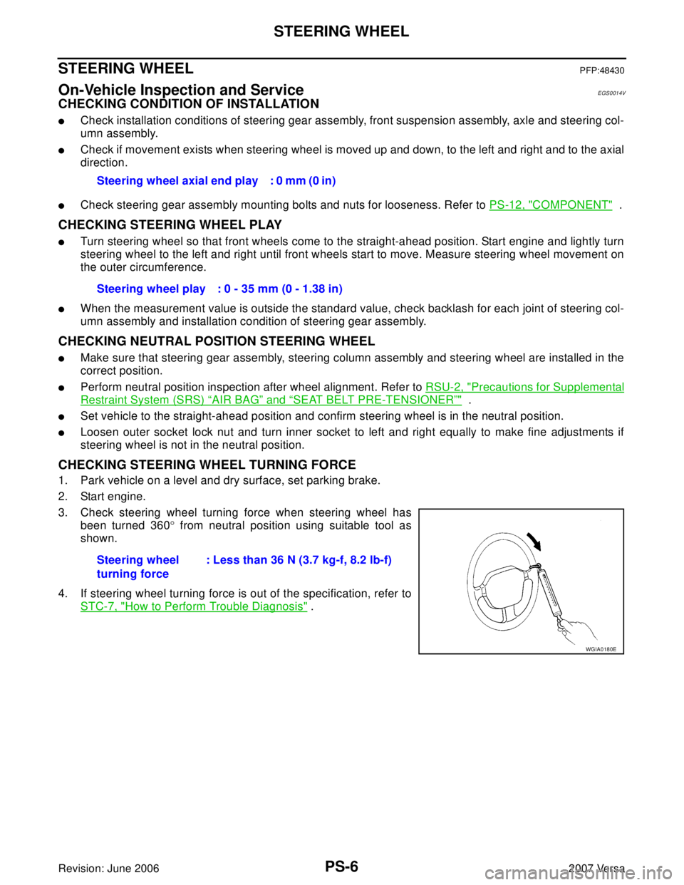
3. Check steering wheel turning force when steering wheel has
been turned 360° from neutral position using suitable tool as
shown.
4. If steering wheel turning force is out of the specification, refer to
STC-7, "
How to Perform Trouble Diagnosis" . Steering wheel axial end play : 0 mm (0 in)
Steering wheel play : 0 - 35 mm (0 - 1.38 in)
Steering wheel
turning force: Less than 36 N (3.7 kg-f, 8.2 lb-f)
WGIA0180E
Page 2601 of 2896

STEERING WHEEL
PS-7
C
D
E
F
H
I
J
K
L
MA
B
PS
Revision: June 20062007 Versa
CHECKING FRONT WHEEL TURNING ANGLE
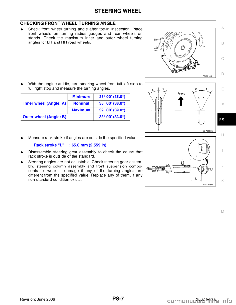
�Check front wheel turning angle after toe-in inspection. Place
front wheels on turning radius gauges and rear wheels on
stands. Check the maximum inner and outer wheel turning
angles for LH and RH road wheels.
�With the engine at idle, turn steering wheel from full left stop to
full right stop and measure the turning angles.
�Measure rack stroke if angles are outside the specified value.
�Disassemble steering gear assembly to check the cause that
rack stroke is outside of the standard.
�Steering angles are not adjustable. Check steering gear assem-
bly, steering column assembly and front suspension compo-
nents for wear or damage if any of the turning angles are
different from the specified value. Replace any of them, if any
non-standard condition exists.
FAA0016D
Inner wheel (Angle: A)Minimum 35° 00′ (35.0°)
Nominal 38° 00′ (38.0°)
Maximum 39° 00′ (39.0°)
Outer wheel (Angle: B) 33° 00′ (33.0°)
SGIA0055E
Rack stroke “L” : 65.0 mm (2.559 in)
WGIA0181E
Page 2621 of 2896
PREPARATION
RF-3
C
D
E
F
G
H
J
K
L
MA
B
RF
Revision: June 20062007 Versa
PREPARATIONPFP:00002
Commercial Service ToolsEIS0095T
Tool name Description
Engine ear Locating the noise
SIIA0995E
Page 2623 of 2896

SQUEAK AND RATTLE TROUBLE DIAGNOSES
RF-5
C
D
E
F
G
H
J
K
L
MA
B
RF
Revision: June 20062007 Versa
DUPLICATE THE NOISE AND TEST DRIVE
If possible, drive the vehicle with the customer until the noise is duplicated. Note any additional information on
the Diagnostic Worksheet regarding the conditions or location of the noise. This information can be used to
duplicate the same conditions when you confirm the repair.
If the noise can be duplicated easily during the test drive, to help identify the source of the noise, try to dupli-
cate the noise with the vehicle stopped by doing one or all of the following:
1) Close a door.
2) Tap or push/pull around the area where the noise appears to be coming from.
3) Rev the engine.
4) Use a floor jack to recreate vehicle “twist”.
5) At idle, apply engine load (electrical load, half-clutch on M/T model, drive position on A/T model).
6) Raise the vehicle on a hoist and hit a tire with a rubber hammer.
�Drive the vehicle and attempt to duplicate the conditions the customer states exist when the noise occurs.
�If it is difficult to duplicate the noise, drive the vehicle slowly on an undulating or rough road to stress the
vehicle body.
CHECK RELATED SERVICE BULLETINS
After verifying the customer concern or symptom, check ASIST for Technical Service Bulletins (TSBs) related
to that concern or symptom.
If a TSB relates to the symptom, follow the procedure to repair the noise.
LOCATE THE NOISE AND IDENTIFY THE ROOT CAUSE
1. Narrow down the noise to a general area. To help pinpoint the source of the noise, use a listening tool
(Engine Ear or mechanics stethoscope).
2. Narrow down the noise to a more specific area and identify the cause of the noise by:
�removing the components in the area that you suspect the noise is coming from.
Do not use too much force when removing clips and fasteners, otherwise clips and fastener can be broken
or lost during the repair, resulting in the creation of new noise.
�tapping or pushing/pulling the component that you suspect is causing the noise.
Do not tap or push/pull the component with excessive force, otherwise the noise will be eliminated only
temporarily.
�feeling for a vibration with your hand by touching the component(s) that you suspect is (are) causing the
noise.
�placing a piece of paper between components that you suspect are causing the noise.
�looking for loose components and contact marks.
Refer to RF-6, "
Generic Squeak and Rattle Troubleshooting" .
REPAIR THE CAUSE
�If the cause is a loose component, tighten the component securely.
�If the cause is insufficient clearance between components:
–separate components by repositioning or loosening and retightening the component, if possible.
–insulate components with a suitable insulator such as urethane pads, foam blocks, felt cloth tape or ure-
thane tape are available through your authorized Nissan Parts Department.
CAUTION:
Do not use excessive force as many components are constructed of plastic and may be damaged.
NOTE:
Always check with the Parts Department for the latest parts information.
Each item can be ordered separately as needed.
URETHANE PADS [1.5 mm (0.059 in) thick]
Insulates connectors, harness, etc.
76268-9E005: 100 × 135 mm (3.94 × 5.31 in)/76884-71L01: 60 × 85 mm (2.36 × 3.35 in)/76884-71L02: 15 ×
25 mm (0.59 × 0.98 in)
INSULATOR (Foam blocks)
Insulates components from contact. Can be used to fill space behind a panel.
73982-9E000: 45 mm (1.77 in) thick, 50 × 50 mm (1.97 × 1.97 in)/73982-50Y00: 10 mm (0.39 in) thick, 50
× 50 mm (1.97 × 1.97 in)
INSULATOR (Light foam block)
80845-71L00: 30 mm (1.18 in) thick, 30 × 50 mm (1.18 × 1.97 in)