Page 2545 of 2896

IPDM E/R (INTELLIGENT POWER DISTRIBUTION MODULE ENGINE ROOM)
PG-29
C
D
E
F
G
H
I
J
L
MA
B
PG
Revision: June 20062007 Versa
Inspection with CONSULT-II (Self-Diagnosis)EKS00JLR
CAUTION:
If a CONSULT-II is used with no connection of CONSULT-II CONVERTER, malfunctions might be
detected in self-diagnosis depending on which control unit(s) carry out CAN communication.
1. SELF-DIAGNOSIS RESULT CHECK
1. Connect CONSULT-II and select "IPDM E/R" on the "SELECT SYSTEM" screen.
2. Select "SELF-DIAG RESULTS" on the "SELECT DIAG MODE" screen.
3. Check display content in self-diagnosis results.
NOTE:
The Details for Display for the Period are as follows:
�CRNT: Error currently detected by IPDM E/R.
�PAST: Error detected in the past and stored in IPDM E/R memory.
Contents displayed
NO DTC DETECTED. FURTHER TESTING MAY BE REQUIRED.>>Inspection End.
CAN COMM CIRC>>Print out the self-diagnosis result and refer to LAN-4, "
SYSTEM DESCRIPTION" .
Removal and Installation of IPDM E/REKS00JWA
: Vehicle front
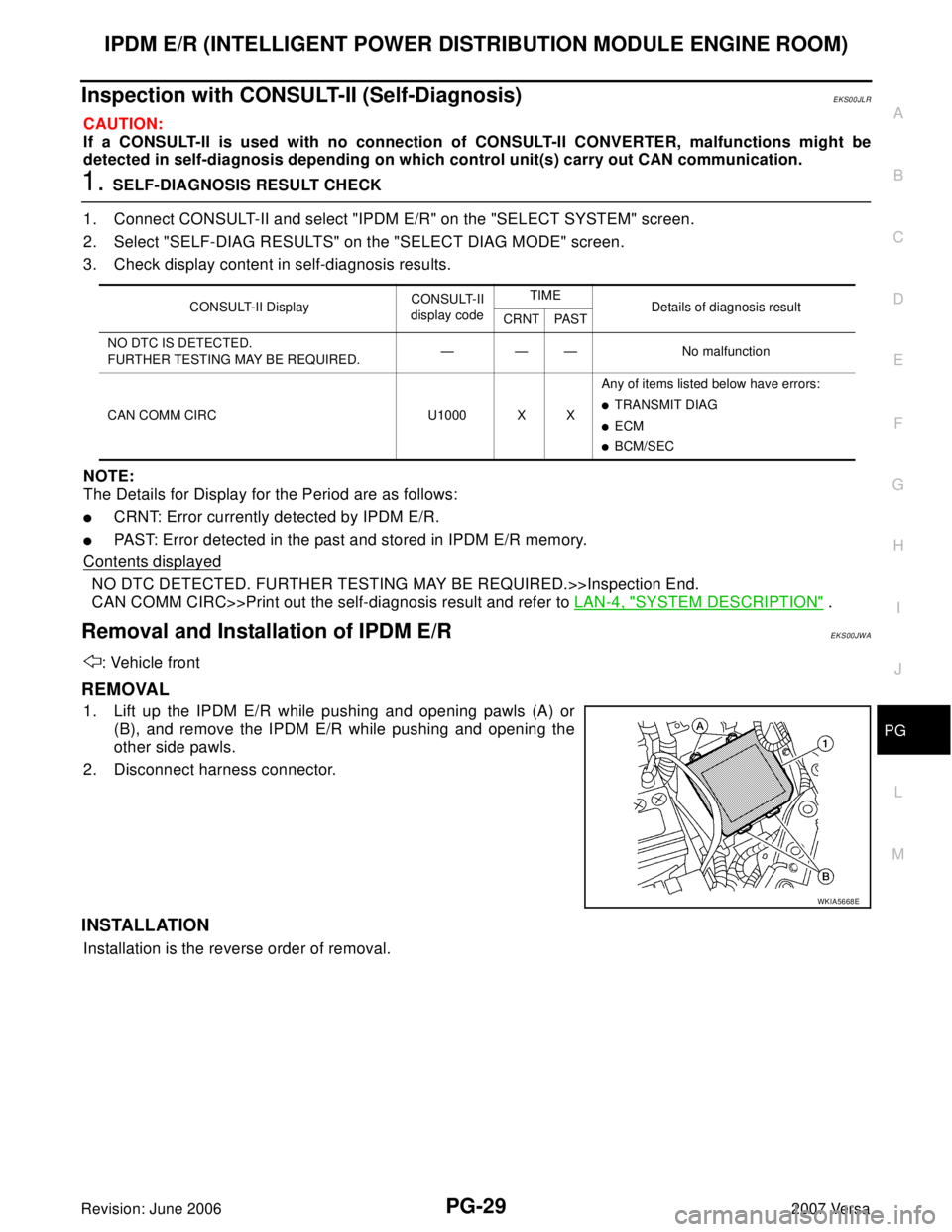
REMOVAL
1. Lift up the IPDM E/R while pushing and opening pawls (A) or
(B), and remove the IPDM E/R while pushing and opening the
other side pawls.
2. Disconnect harness connector.
INSTALLATION
Installation is the reverse order of removal.
CONSULT-II DisplayCONSULT-II
display codeTIME
Details of diagnosis result
CRNT PAST
NO DTC IS DETECTED.
FURTHER TESTING MAY BE REQUIRED.— — — No malfunction
CAN COMM CIRC U1000 X XAny of items listed below have errors:
�TRANSMIT DIAG
�ECM
�BCM/SEC
WKIA5668E
Page 2549 of 2896
GROUND CIRCUIT
PG-33
C
D
E
F
G
H
I
J
L
MA
B
PG
Revision: June 20062007 Versa
ENGINE ROOM HARNESS
WKIA5646E
Page 2551 of 2896
GROUND CIRCUIT
PG-35
C
D
E
F
G
H
I
J
L
MA
B
PG
Revision: June 20062007 Versa
ENGINE CONTROL HARNESS
WKIA5648E
Page 2555 of 2896
HARNESS
PG-39
C
D
E
F
G
H
I
J
L
MA
B
PG
Revision: June 20062007 Versa
HARNESSPFP:24010
Harness LayoutEKS00IW8
HOW TO READ HARNESS LAYOUT
The following Harness Layouts use a map style grid to help locate
connectors on the drawings:
�Main Harness
�Engine Room Harness (LH View)
�Engine Room Harness (RH View)
�Engine Control Harness
�Body Harness
�Body No. 2 Harness
�Room Lamp Harness
�Back Door Harness
To use the grid reference
1. Find the desired connector number on the connector list.
2. Find the grid reference.
3. On the drawing, find the crossing of the grid reference letter column and number row.
4. Find the connector number in the crossing zone.
5. Follow the line to the connector.SEL252V
Page 2559 of 2896
HARNESS
PG-43
C
D
E
F
G
H
I
J
L
MA
B
PG
Revision: June 20062007 Versa
ENGINE ROOM HARNESS (LH VIEW)
Refer to PG-45, "ENGINE ROOM HARNESS (RH VIEW)" for continuation of engine room harness.
LKIA0815E
Page 2560 of 2896

PG-44
HARNESS
Revision: June 20062007 Versa
C4 E3 GR/4 : Cooling fan motor (without A/C) C3 E47 BR/8: IPDM E/R (Intelligent Power Distribu-
tion Module Engine Room)
C4 E3 B/2 : Cooling fan motor (with A/C) D3 E48 B/6: IPDM E/R (Intelligent Power Distribu-
tion Module Engine Room)
C4 E5 GR/3 : Resistor D1 E51 B/2 : Front wheel sensor LH
C3 E6 — : Fuse and fusible link box D3 E53 B/2: Front combination lamp LH
(parking)
B1 E7 SMJ : To M69
D3 E8 SMJ : To F8
B4 E9 BR/2 : Fusible link box (battery)
B3 E10 GR/2 : Fusible link box (battery)
B1 E11 B/2 : To M78
A3 E12 B/6 : Accelerator pedal position sensor
A2 E13 B/2 : Stop lamp switch (with M/T)
A2 E13 W/4 : Stop lamp switch (without M/T)
D3 E14 — : Engine ground (crash zone sensor)
C2 E15 — : Engine ground
B2 E16 B/32 : ECM
C5 E18 B/1 : Horn (low)
C4 E19 GR/6 : To F33
D5 E20 B/1 : Horn (low)
D3 E25 B/3: Front combination lamp LH
(headlamp)
E4 E27 B/2 : Front fog lamp LH
D4 E29 B/2: Front combination lamp LH
(turn signal)
B1 E31 W/24 : TCM
B1 E32 GR/24 : TCM
A2 E34 BR/2 : Clutch interlock switch (with M/T)
A2 E35 BR/2 : ASCD clutch switch
A2 E36 BR/2 : ASCD brake switch
B4 E40 GR/2 : Brake fluid level switch
D3 E42 B/2: IPDM E/R (Intelligent Power Distribu-
tion Module Engine Room)
C3 E43 W/16: IPDM E/R (Intelligent Power Distribu-
tion Module Engine Room)
C3 E44 W/6: IPDM E/R (Intelligent Power Distribu-
tion Module Engine Room)
D3 E45 BR/12: IPDM E/R (Intelligent Power Distribu-
tion Module Engine Room)
D3 E46 W/12: IPDM E/R (Intelligent Power Distribu-
tion Module Engine Room)
Page 2561 of 2896
HARNESS
PG-45
C
D
E
F
G
H
I
J
L
MA
B
PG
Revision: June 20062007 Versa
ENGINE ROOM HARNESS (RH VIEW)
Refer to PG-43, "ENGINE ROOM HARNESS (LH VIEW)" for continuation of engine room harness.
LKIA0816E
Page 2562 of 2896
PG-46
HARNESS
Revision: June 20062007 Versa
G2 E1 GR/5 : Front wiper motor D3 E30 B/2: Front combination lamp RH
(turn signal)
C3 E2 B/2 : Front and rear washer motor F2 E33 B/26: ABS actuator and electric unit (control
unit)
F5 E4 Y/2 : Crash zone sensor E2 E37 B/5 : Daytime light relay 1
E4 E17 B/3 : Refrigerant pressure sensor D2 E38 L/5 : Daytime light relay 2
E5 E21 B/1 : Horn (high) E2 E41 — : Ground (ABS)
E5 E22 B/1 : Horn (high) C3 E50 W/2 : Washer fluid level switch
D2 E24 — : Engine ground D1 E52 B/2 : Front wheel sensor RH
C3 E26 B/3: Front combination lamp RH
(headlamp)D2 E54 B/2: Front combination lamp RH
(parking)
C4 E28 B/2 : Front fog lamp RH