2006 NISSAN PATROL diagnosis mode
[x] Cancel search: diagnosis modePage 3 of 1226
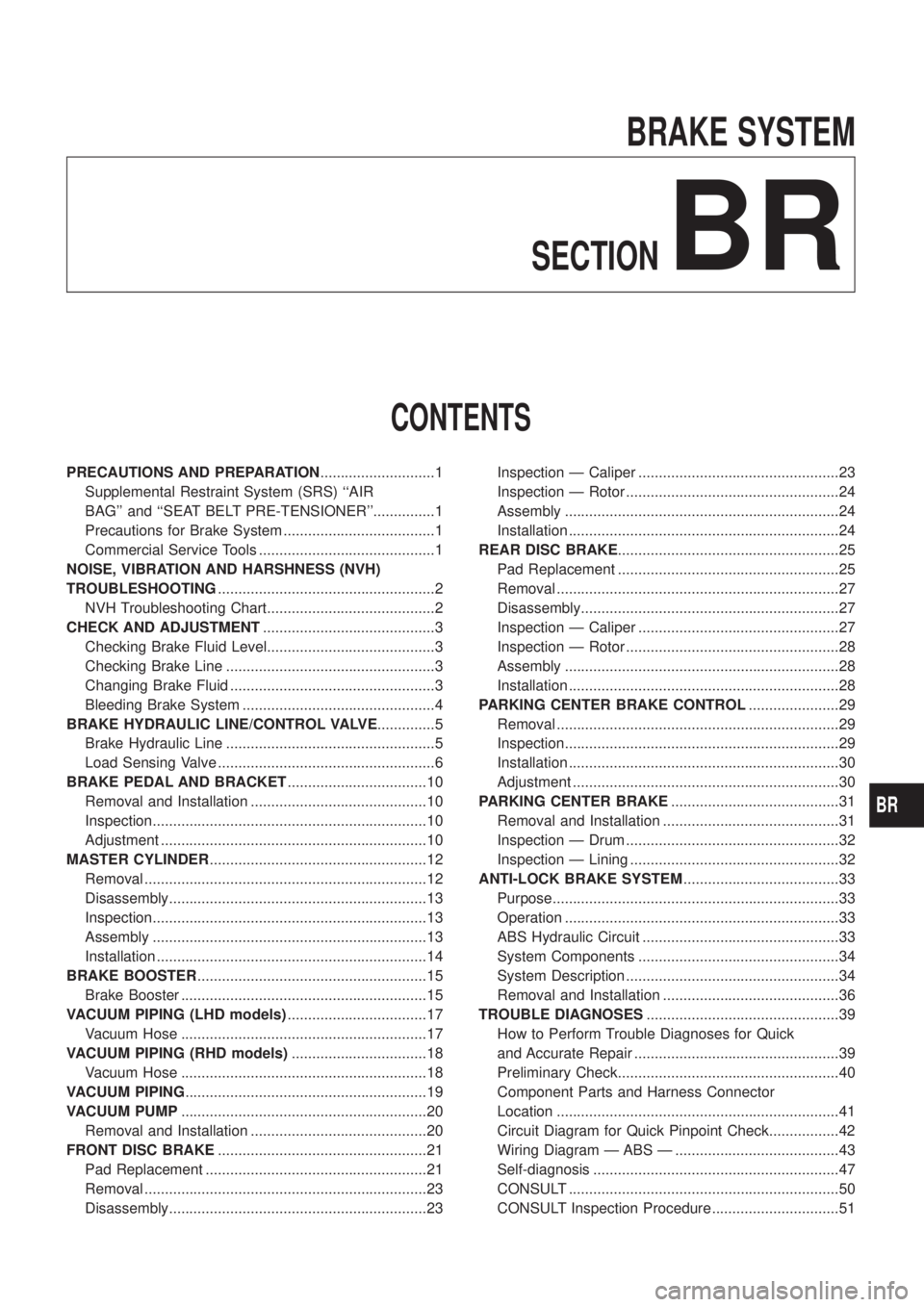
BRAKE SYSTEM
SECTION
BR
CONTENTS
PRECAUTIONS AND PREPARATION ............................1
Supplemental Restraint System (SRS) ``AIR
BAG'' and ``SEAT BELT PRE-TENSIONER''...............1
Precautions for Brake System .....................................1
Commercial Service Tools ...........................................1
NOISE, VIBRATION AND HARSHNESS (NVH)
TROUBLESHOOTING .....................................................2
NVH Troubleshooting Chart.........................................2
CHECK AND ADJUSTMENT ..........................................3
Checking Brake Fluid Level.........................................3
Checking Brake Line ...................................................3
Changing Brake Fluid ..................................................3
Bleeding Brake System ...............................................4
BRAKE HYDRAULIC LINE/CONTROL VALVE ..............5
Brake Hydraulic Line ...................................................5
Load Sensing Valve .....................................................6
BRAKE PEDAL AND BRACKET ..................................10
Removal and Installation ...........................................10
Inspection...................................................................10
Adjustment .................................................................10
MASTER CYLINDER .....................................................12
Removal .....................................................................12
Disassembly...............................................................13
Inspection...................................................................13
Assembly ...................................................................13
Installation ..................................................................14
BRAKE BOOSTER ........................................................15
Brake Booster ............................................................15
VACUUM PIPING (LHD models) ..................................17
Vacuum Hose ............................................................17
VACUUM PIPING (RHD models) .................................18
Vacuum Hose ............................................................18
VACUUM PIPING ...........................................................19
VACUUM PUMP ............................................................20
Removal and Installation ...........................................20
FRONT DISC BRAKE ...................................................21
Pad Replacement ......................................................21
Removal .....................................................................23
Disassembly...............................................................23 Inspection Ð Caliper .................................................23
Inspection Ð Rotor ....................................................24
Assembly ...................................................................24
Installation ..................................................................24
REAR DISC BRAKE ......................................................25
Pad Replacement ......................................................25
Removal .....................................................................27
Disassembly...............................................................27
Inspection Ð Caliper .................................................27
Inspection Ð Rotor ....................................................28
Assembly ...................................................................28
Installation ..................................................................28
PARKING CENTER BRAKE CONTROL ......................29
Removal .....................................................................29
Inspection...................................................................29
Installation ..................................................................30
Adjustment .................................................................30
PARKING CENTER BRAKE .........................................31
Removal and Installation ...........................................31
Inspection Ð Drum ....................................................32
Inspection Ð Lining ...................................................32
ANTI-LOCK BRAKE SYSTEM ......................................33
Purpose......................................................................33
Operation ...................................................................33
ABS Hydraulic Circuit ................................................33
System Components .................................................34
System Description ....................................................34
Removal and Installation ...........................................36
TROUBLE DIAGNOSES ...............................................39
How to Perform Trouble Diagnoses for Quick
and Accurate Repair ..................................................39
Preliminary Check......................................................40
Component Parts and Harness Connector
Location .....................................................................41
Circuit Diagram for Quick Pinpoint Check.................42
Wiring Diagram Ð ABS Ð ........................................43
Self-diagnosis ............................................................47
CONSULT ..................................................................50
CONSULT Inspection Procedure...............................51
BR
Page 5 of 1226
Supplemental Restraint System (SRS) ``AIR
BAG'' and ``SEAT BELT PRE-TENSIONER''
The Supplemental Restraint System such as ``AIR BAG'' and ``SEAT BELT PRE-TENSIONER'' used along with
a seat belt, helps to reduce the risk or severity of injury to the driver and front passenger in a frontal collision.
The SRS system composition which is available to NISSAN MODEL Y61 is as follows (The composition var-
ies according to the destination.):
Driver air bag module (located in the center of the steering wheel), front passenger air bag module (located
on the instrument panel on passenger side), seat belt pre-tensioner, a diagnosis sensor unit, warning lamp,
wiring harness and spiral cable.
Information necessary to service the system safely is included in theRS sectionof this Service Manual.
WARNING:
+ To avoid rendering the SRS inoperative, which could increase the risk of personal injury or death
in the event of a collision which would result in air bag in¯ation, all maintenance must be performed
by an authorized NISSAN dealer.
+ Improper maintenance, including incorrect removal and installation of the SRS, can lead to per-
sonal injury caused by unintentional activation of the system. For removal of Spiral Cable and Air
Bag Module, see the RS section.
+ Do not use electrical test equipment on any circuit related to the SRS unless instructed to in this
Service Manual. Spiral Cable and wiring harnesses covered with yellow insulation either just before
the harness connectors or for the complete harness are related to the SRS.
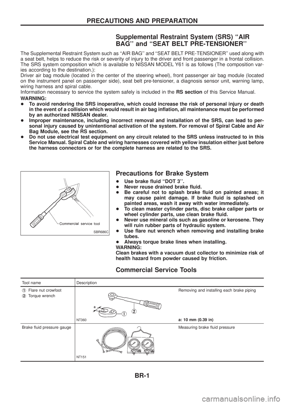
Precautions for Brake System
+Use brake ¯uid ``DOT 3''.
+ Never reuse drained brake ¯uid.
+ Be careful not to splash brake ¯uid on painted areas; it
may cause paint damage. If brake ¯uid is splashed on
painted areas, wash it away with water immediately.
+ To clean master cylinder parts, disc brake caliper parts or
wheel cylinder parts, use clean brake ¯uid.
+ Never use mineral oils such as gasoline or kerosene. They
will ruin rubber parts of hydraulic system.
+ Use ¯are nut wrench when removing and installing brake
tubes.
+ Always torque brake lines when installing.
WARNING:
Clean brakes with a vacuum dust collector to minimize risk of
health hazard from powder caused by friction.
Commercial Service Tools
Tool name Description
j
1Flare nut crowfoot
j
2Torque wrench
NT360
Removing and installing each brake piping
a: 10 mm (0.39 in)
Brake ¯uid pressure gauge
NT151
Measuring brake ¯uid pressure
SBR686C
PRECAUTIONS AND PREPARATION
BR-1
Page 51 of 1226
Self-diagnosis
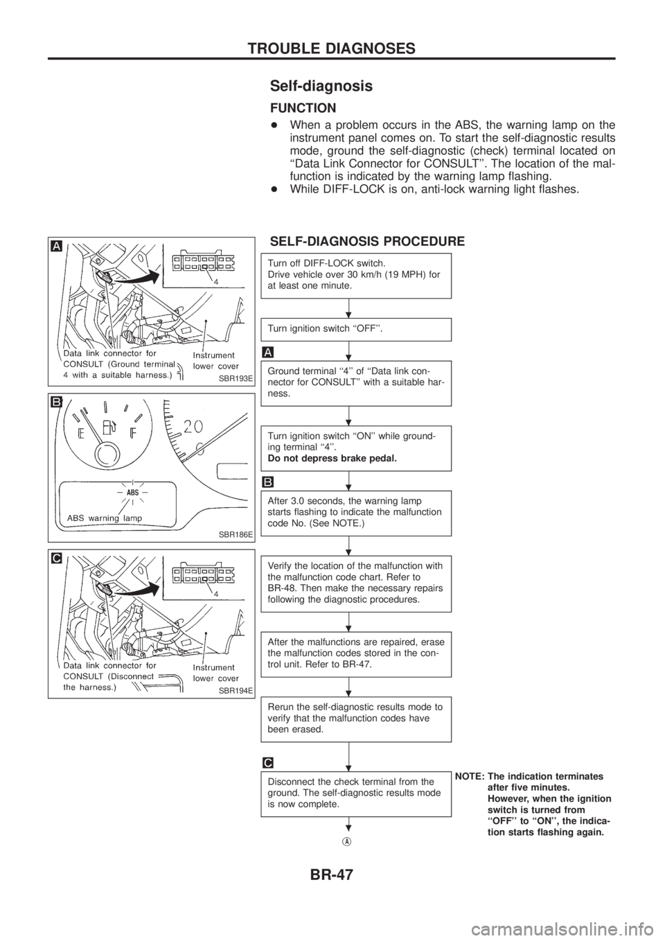
FUNCTION
+When a problem occurs in the ABS, the warning lamp on the
instrument panel comes on. To start the self-diagnostic results
mode, ground the self-diagnostic (check) terminal located on
``Data Link Connector for CONSULT''. The location of the mal-
function is indicated by the warning lamp ¯ashing.
+ While DIFF-LOCK is on, anti-lock warning light ¯ashes.
SELF-DIAGNOSIS PROCEDURE
Turn off DIFF-LOCK switch.
Drive vehicle over 30 km/h (19 MPH) for
at least one minute.
Turn ignition switch ``OFF''.
Ground terminal ``4'' of ``Data link con-
nector for CONSULT'' with a suitable har-
ness.
Turn ignition switch ``ON'' while ground-
ing terminal ``4''.
Do not depress brake pedal.
After 3.0 seconds, the warning lamp
starts ¯ashing to indicate the malfunction
code No. (See NOTE.)
Verify the location of the malfunction with
the malfunction code chart. Refer to
BR-48. Then make the necessary repairs
following the diagnostic procedures.
After the malfunctions are repaired, erase
the malfunction codes stored in the con-
trol unit. Refer to BR-47.
Rerun the self-diagnostic results mode to
verify that the malfunction codes have
been erased.
Disconnect the check terminal from the
ground. The self-diagnostic results mode
is now complete.NOTE: The indication terminates
after ®ve minutes.
However, when the ignition
switch is turned from
``OFF'' to ``ON'', the indica-
tion starts ¯ashing again.
j
A
SBR193E
SBR186E
SBR194E
.
.
.
.
.
.
.
.
.
TROUBLE DIAGNOSES
BR-47
Page 54 of 1226
CONSULT
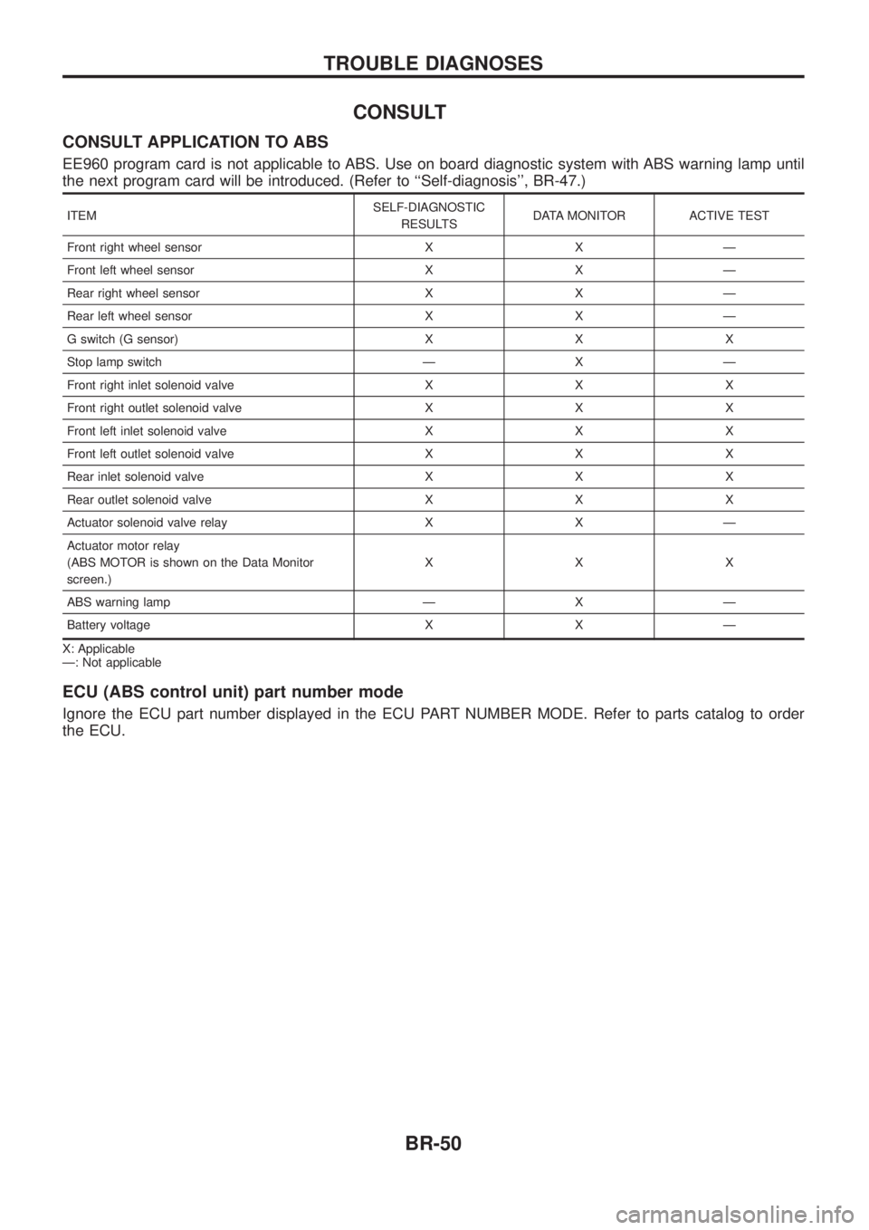
CONSULT APPLICATION TO ABS
EE960 program card is not applicable to ABS. Use on board diagnostic system with ABS warning lamp until
the next program card will be introduced. (Refer to ``Self-diagnosis'', BR-47.)
ITEMSELF-DIAGNOSTIC
RESULTS DATA MONITOR ACTIVE TEST
Front right wheel sensor X X Ð
Front left wheel sensor X X Ð
Rear right wheel sensor X X Ð
Rear left wheel sensor X X Ð
G switch (G sensor) X X X
Stop lamp switch Ð X Ð
Front right inlet solenoid valve X X X
Front right outlet solenoid valve X X X
Front left inlet solenoid valve X X X
Front left outlet solenoid valve X X X
Rear inlet solenoid valve X X X
Rear outlet solenoid valve X X X
Actuator solenoid valve relay X X Ð
Actuator motor relay
(ABS MOTOR is shown on the Data Monitor
screen.) XXX
ABS warning lamp Ð X Ð
Battery voltage X X Ð
X: Applicable
Ð: Not applicable
ECU (ABS control unit) part number mode
Ignore the ECU part number displayed in the ECU PART NUMBER MODE. Refer to parts catalog to order
the ECU.
TROUBLE DIAGNOSES
BR-50
Page 56 of 1226
![NISSAN PATROL 2006 Service Manual SELF-DIAGNOSTIC RESULTS MODE
Diagnostic item Diagnostic item is detected when ...Diagnostic
procedure
FR RH SENSOR .1
[OPEN] +
Circuit for front right wheel sensor is open.
(An abnormally high input v](/manual-img/5/57368/w960_57368-55.png "NISSAN PATROL 2006 Service Manual SELF-DIAGNOSTIC RESULTS MODE
Diagnostic item Diagnostic item is detected when ...Diagnostic
procedure
FR RH SENSOR .1
[OPEN] +
Circuit for front right wheel sensor is open.
(An abnormally high input v")
SELF-DIAGNOSTIC RESULTS MODE
Diagnostic item Diagnostic item is detected when ...Diagnostic
procedure
FR RH SENSOR .1
[OPEN] +
Circuit for front right wheel sensor is open.
(An abnormally high input voltage is entered.) 1
FR LH SENSOR .1
[OPEN] +
Circuit for front left wheel sensor is open.
(An abnormally high input voltage is entered.) 1
RR RH SENSOR .1
[OPEN] +
Circuit for rear right sensor is open.
(An abnormally high input voltage is entered.) 1
RR LH SENSOR .1
[OPEN] +
Circuit for rear left sensor is open.
(An abnormally high input voltage is entered.) 1
FR RH SENSOR .1
[SHORT] +
Circuit for front right wheel sensor is shorted.
(An abnormally low input voltage is entered.) 1
FR LH SENSOR .1
[SHORT] +
Circuit for front left wheel sensor is shorted.
(An abnormally low input voltage is entered.) 1
RR RH SENSOR .1
[SHORT] +
Circuit for rear right sensor is shorted.
(An abnormally low input voltage is entered.) 1
RR LH SENSOR .1
[SHORT] +
Circuit for rear left sensor is shorted.
(An abnormally low input voltage is entered.) 1
ABS SENSOR .1
[ABNORMAL SIGNAL] +
Teeth damage on sensor rotor or improper installation of wheel sensor.
(Abnormal wheel sensor signal is entered.) 1
FR RH IN ABS SOL
[OPEN] +
Circuit for front right inlet solenoid valve is open.
(An abnormally low output voltage is entered.) 2
FR LH IN ABS SOL
[OPEN] +
Circuit for front left inlet solenoid valve is open.
(An abnormally low output voltage is entered.) 2
RR IN ABS SOL
[OPEN] +
Circuit for rear inlet solenoid valve is open.
(An abnormally low output voltage is entered.) 2
FR RH IN ABS SOL
[SHORT] +
Circuit for front right inlet solenoid valve is shorted.
(An abnormally high output voltage is entered.) 2
FR LH IN ABS SOL
[SHORT] +
Circuit for front left inlet solenoid valve is shorted.
(An abnormally high output voltage is entered.) 2
RR IN ABS SOL
[SHORT] +
Circuit for rear inlet solenoid valve is shorted.
(An abnormally high output voltage is entered.) 2
FR RH OUT ABS SOL
[OPEN] +
Circuit for front right outlet solenoid valve is open.
(An abnormally low output voltage is entered.) 2
FR LH OUT ABS SOL
[OPEN] +
Circuit for front left outlet solenoid valve is open.
(An abnormally low output voltage is entered.) 2
RR OUT ABS SOL
[OPEN] +
Circuit for rear outlet solenoid valve is open.
(An abnormally low output voltage is entered.) 2
FR RH OUT ABS SOL
[SHORT] +
Circuit for front right outlet solenoid valve is shorted.
(An abnormally high output voltage is entered.) 2
FR LH OUT ABS SOL
[SHORT] +
Circuit for front left outlet solenoid valve is shorted.
(An abnormally high output voltage is entered.) 2
RR OUT ABS SOL
[SHORT] +
Circuit for rear outlet solenoid valve is shorted.
(An abnormally high output voltage is entered.) 2
ABS ACTUATOR RELAY
[ABNORMAL] +
Actuator solenoid valve relay is ON, even if control unit sends off signal.
+ Actuator solenoid valve relay is OFF, even if control unit sends on signal. 2
ABS MOTOR RELAY
[ABNORMAL] +
Circuit for ABS motor relay is open or shorted.
+ Circuit for actuator motor is open or shorted.
+ Actuator motor relay is stuck. 3
BATTERY VOLT
[VB-LOW] +
Power source voltage supplied to ABS control unit is abnormally low. 4
CONTROL UNIT +Function of calculation in ABS control unit has failed. 6
G-SENSOR
[ABNORMAL] +
G sensor circuit is open or shorted. 5
. 1: If one or more wheels spin on a rough or slippery road for 40 seconds or more, the ABS warning lamp will illuminate. This does
not indicate a malfunction. Only in the case of the short-circuit (Code Nos. 26, 22, 32 and 36), after repair the ABS warning
lamp also illuminates when the ignition switch is turned ``ON''. In this case, drive the vehicle at speeds greater than 30 km/h (19
MPH) for approximately 1 minute as speci®ed in ``SELF-DIAGNOSIS PROCEDURE'', BR-47. Check to ensure that the ABS
warning lamp goes out while the vehicle is being driven.
TROUBLE DIAGNOSES
CONSULT Inspection Procedure (Cont'd)
BR-52
Page 79 of 1226

Service Notice
+When removing or installing various parts, place a cloth or padding onto the vehicle body to prevent
scratches.
+Handle trim, molding, instruments, grille, etc. carefully during removing or installing. Be careful not to soil
or damage them.
+Apply sealing compound where necessary when installing parts.
+When applying sealing compound, be careful that the sealing compound does not protrude from parts.
+When replacing any metal parts (for example body outer panel, members, etc.), be sure to take rust pre-
vention measures.
Supplemental Restraint System (SRS) ``AIR
BAG'' and ``SEAT BELT PRE-TENSIONER''
The Supplemental Restraint System such as ``AIR BAG'' and ``SEAT BELT PRE-TENSIONER'' used along with
a seat belt, helps to reduce the risk or severity of injury to the driver and front passenger in a frontal collision.
The SRS system composition which is available to NISSAN MODEL Y61 is as follows (The composition var-
ies according to the destination.):
Driver air bag module (located in the center of the steering wheel), front passenger air bag module (located
on the instrument panel on passenger side), seat belt pre-tensioner, a diagnosis sensor unit, warning lamp,
wiring harness and spiral cable.
Information necessary to service the system safely is included in theRS sectionof this Service Manual.
WARNING:
+To avoid rendering the SRS inoperative, which could increase the risk of personal injury or death
in the event of a collision which would result in air bag in¯ation, all maintenance must be performed
by an authorized NISSAN dealer.
+Improper maintenance, including incorrect removal and installation of the SRS, can lead to per-
sonal injury caused by unintentional activation of the system. For removal of Spiral Cable and Air
Bag Module, see the RS section.
+Do not use electrical test equipment on any circuit related to the SRS unless instructed to in this
Service Manual. Spiral cable and wiring harnesses covered with yellow insulation either just before
the harness connectors or for the complete harness are related to the SRS.
PRECAUTIONS
BT-1
Page 150 of 1226
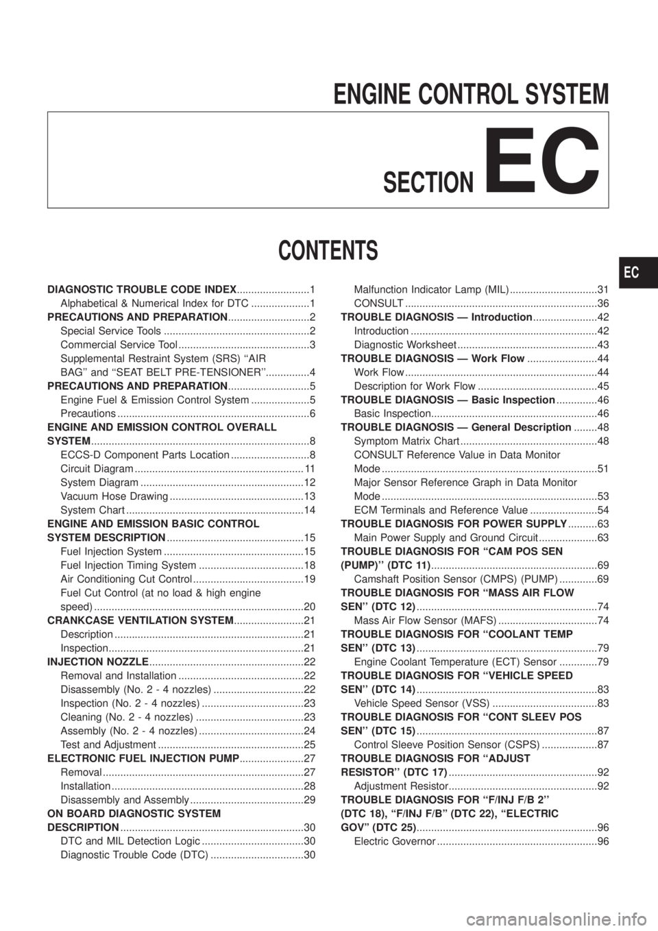
ENGINE CONTROL SYSTEMSECTION
EC
CONTENTS
DIAGNOSTIC TROUBLE CODE INDEX .........................1
Alphabetical & Numerical Index for DTC ....................1
PRECAUTIONS AND PREPARATION ............................2
Special Service Tools ..................................................2
Commercial Service Tool .............................................3
Supplemental Restraint System (SRS) ``AIR
BAG'' and ``SEAT BELT PRE-TENSIONER''...............4
PRECAUTIONS AND PREPARATION ............................5
Engine Fuel & Emission Control System ....................5
Precautions ..................................................................6
ENGINE AND EMISSION CONTROL OVERALL
SYSTEM ........................................................................\
...8
ECCS-D Component Parts Location ...........................8
Circuit Diagram .......................................................... 11
System Diagram ........................................................12
Vacuum Hose Drawing ..............................................13
System Chart .............................................................14
ENGINE AND EMISSION BASIC CONTROL
SYSTEM DESCRIPTION ...............................................15
Fuel Injection System ................................................15
Fuel Injection Timing System ....................................18
Air Conditioning Cut Control ......................................19
Fuel Cut Control (at no load & high engine
speed) ........................................................................\
20
CRANKCASE VENTILATION SYSTEM ........................21
Description .................................................................21
Inspection...................................................................21
INJECTION NOZZLE .....................................................22
Removal and Installation ...........................................22
Disassembly (No. 2 - 4 nozzles) ...............................22
Inspection (No. 2 - 4 nozzles) ...................................23
Cleaning (No. 2 - 4 nozzles) .....................................23
Assembly (No. 2 - 4 nozzles) ....................................24
Test and Adjustment ..................................................25
ELECTRONIC FUEL INJECTION PUMP ......................27
Removal .....................................................................27
Installation ..................................................................28
Disassembly and Assembly .......................................29
ON BOARD DIAGNOSTIC SYSTEM
DESCRIPTION ...............................................................30
DTC and MIL Detection Logic ...................................30
Diagnostic Trouble Code (DTC) ................................30 Malfunction Indicator Lamp (MIL) ..............................31
CONSULT ..................................................................36
TROUBLE DIAGNOSIS Ð Introduction ......................42
Introduction ................................................................42
Diagnostic Worksheet ................................................43
TROUBLE DIAGNOSIS Ð Work Flow ........................44
Work Flow ..................................................................44
Description for Work Flow .........................................45
TROUBLE DIAGNOSIS Ð Basic Inspection ..............46
Basic Inspection.........................................................46
TROUBLE DIAGNOSIS Ð General Description ........48
Symptom Matrix Chart ...............................................48
CONSULT Reference Value in Data Monitor
Mode ........................................................................\
..51
Major Sensor Reference Graph in Data Monitor
Mode ........................................................................\
..53
ECM Terminals and Reference Value .......................54
TROUBLEDIAGNOSISFORPOWERSUPPLY ..........63
MainPowerSupplyandGroundCircuit....................63
TROUBLE DIAGNOSIS FOR ``CAM POS SEN
(PUMP)''(DTC11) .........................................................69
CamshaftPositionSensor(CMPS)(PUMP).............69
TROUBLEDIAGNOSISFOR``MASSAIRFLOW
SEN''(DTC12) ..............................................................74
MassAirFlowSensor(MAFS)..................................74
TROUBLEDIAGNOSISFOR``COOLANTTEMP
SEN''(DTC13) ..............................................................79
EngineCoolantTemperature(ECT)Sensor.............79
TROUBLEDIAGNOSISFOR``VEHICLESPEED
SEN''(DTC14) ..............................................................83
VehicleSpeedSensor(VSS)....................................83
TROUBLEDIAGNOSISFOR``CONTSLEEVPOS
SEN''(DTC15) ..............................................................87
ControlSleevePositionSensor(CSPS)...................87
TROUBLEDIAGNOSISFOR``ADJUST
RESISTOR''(DTC17) ...................................................92
AdjustmentResistor...................................................92
TROUBLEDIAGNOSISFOR``F/INJF/B2''
(DTC18),``F/INJF/B''(DTC22),``ELECTRIC
GOV''(DTC25) ..............................................................96
ElectricGovernor.......................................................96
EC
Page 155 of 1226
Supplemental Restraint System (SRS) ``AIR
BAG'' and ``SEAT BELT PRE-TENSIONER''
The Supplemental Restraint System such as ``AIR BAG'' and ``SEAT BELT PRE-TENSIONER'' used along with
a seat belt, helps to reduce the risk or severity of injury to the driver and front passenger in a frontal collision.
The SRS system composition which is available to NISSAN MODEL Y61 is as follows (The composition var-
ies according to the destination.):
Driver air bag module (located in the center of the steering wheel), front passenger air bag module (located
on the instrument panel on passenger side), seat belt pre-tensioner, a diagnosis sensor unit, warning lamp,
wiring harness and spiral cable.
Information necessary to service the system safely is included in theRS sectionof this Service Manual.
WARNING:
+To avoid rendering the SRS inoperative, which could increase the risk of personal injury or death
in the event of a collision which would result in air bag in¯ation, all maintenance must be performed
by an authorized NISSAN dealer.
+Improper maintenance, including incorrect removal and installation of the SRS, can lead to per-
sonal injury caused by unintentional activation of the system. For removal of Spiral Cable and Air
Bag Module, see the RS section.
+Do not use electrical test equipment on any circuit related to the SRS unless instructed to in this
Service Manual. Spiral cable and wiring harnesses covered with yellow insulation either just before
the harness connectors or for the complete harness are related to the SRS.
PRECAUTIONS AND PREPARATION
EC-4