2006 NISSAN PATROL General Information
[x] Cancel search: General InformationPage 1 of 1226

Edition: February 1998
Release: February 1998 (01)
Publication No.: SM8E-0Y61E0E
Reference No.: 7711346063GENERAL INFORMATIONGI
MAINTENANCEMA
ENGINE MECHANICALEM
ENGINE LUBRICATION &
COOLING SYSTEMSLC
ENGINE CONTROL SYSTEMEC
ACCELERATOR CONTROL,
FUEL & EXHAUST SYSTEMFE
CLUTCHCL
MANUAL TRANSMISSIONMT
AUTOMATIC TRANSMISSIONAT
TRANSFERTF
PROPELLER SHAFT &
DIFFERENTIAL CARRIERPD
FRONT AXLE & FRONT SUSPENSIONFA
REAR AXLE & REAR SUSPENSIONRA
BRAKE SYSTEMBR
STEERING SYSTEMST
RESTRAINT SYSTEMRS
BODY & TRIMBT
HEATER & AIR CONDITIONERHA
ELECTRICAL SYSTEMEL
ALPHABETICAL INDEXIDX
PATROL GR
MODEL Y61 SERIES
NISSAN EUROPE S.A.S.
1998 NISSAN EUROPE S.A.S.
Produced in The Netherlands
Not to be reproduced in whole or in part
without the prior written permission of
Nissan Europe S.A.S., Paris, France.
QUICK REFERENCE INDEX
Page 194 of 1226
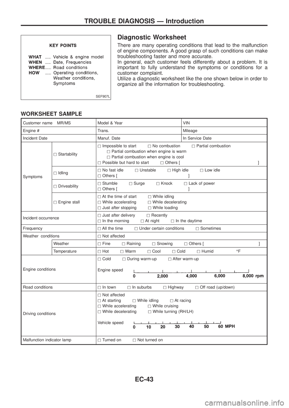
Diagnostic Worksheet
There are many operating conditions that lead to the malfunction
of engine components. A good grasp of such conditions can make
troubleshooting faster and more accurate.
In general, each customer feels differently about a problem. It is
important to fully understand the symptoms or conditions for a
customer complaint.
Utilize a diagnostic worksheet like the one shown below in order to
organize all the information for troubleshooting.
WORKSHEET SAMPLE
Customer name MR/MS Model & Year VIN
Engine # Trans. Mileage
Incident Date Manuf. Date In Service Date
SymptomshStartabilityhImpossible to starthNo combustionhPartial combustion
hPartial combustion when engine is warm
hPartial combustion when engine is cool
hPossible but hard to starthOthers [ ]
hIdlinghNo fast idlehUnstablehHigh idlehLow idle
hOthers [ ]
hDriveabilityhStumblehSurgehKnockhLack of power
hOthers [ ]
hEngine stallhAt the time of starthWhile idling
hWhile acceleratinghWhile decelerating
hJust after stoppinghWhile loading
Incident occurrencehJust after deliveryhRecently
hIn the morninghAt nighthIn the daytime
FrequencyhAll the timehUnder certain conditionshSometimes
Weather conditionshNot affected
WeatherhFinehRaininghSnowinghOthers [ ]
TemperaturehHothWarmhCoolhColdhHumid ÉF
Engine conditionshColdhDuring warm-uphAfter warm-up
Engine speed
Road conditionshIn townhIn suburbshHighwayhOff road (up/down)
Driving conditionshNot affected
hAt startinghWhile idlinghAt racing
hWhile acceleratinghWhile cruising
hWhile deceleratinghWhile turning (RH/LH)
Vehicle speed
Malfunction indicator lamphTurned onhNot turned on
SEF907L
TROUBLE DIAGNOSIS Ð Introduction
EC-43
Page 773 of 1226
GENERAL INFORMATION
SECTION
GI
CONTENTS
PRECAUTIONS...............................................................1
Precaution for Supplemental Restraint System
(SRS) ``AIR BAG'' and ``SEAT BELT
PRE-TENSIONER'' ......................................................1
General Precautions ....................................................2
Precautions for Multiport Fuel Injection System
or ECCS Engine ..........................................................3
Precautions for Three Way Catalyst
(If so equipped)............................................................4
Precautions for Engine Oils .........................................4
Precautions for Fuel ....................................................5
Precautions for Air Conditioning ..................................5
HOW TO USE THIS MANUAL........................................6
HOW TO READ WIRING DIAGRAMS............................8
Sample/Wiring Diagram Ð EXAMPL Ð......................8
Description .................................................................10
HOW TO CHECK TERMINAL.......................................17
How to Probe Connectors .........................................17
How to Check Enlarged Contact Spring of
Terminal .....................................................................18
Waterproof Connector Inspection ..............................19
Terminal Lock Inspection ...........................................19
HOW TO PERFORM EFFICIENT DIAGNOSIS FOR
AN ELECTRICAL INCIDENT........................................20Work Flow ..................................................................20
Incident Simulation Tests ...........................................21
Circuit Inspection .......................................................24
HOW TO FOLLOW FLOW CHART IN TROUBLE
DIAGNOSES..................................................................30
How to Follow This Flow Chart .................................31
CONSULT CHECKING SYSTEM..................................33
Function and System Application ..............................33
Lithium Battery Replacement ....................................33
Checking Equipment..................................................33
Loading Procedure ....................................................34
CONSULT Data Link Connector (DLC) Circuit..........34
IDENTIFICATION INFORMATION.................................35
Model Variation ..........................................................35
Identi®cation Number .................................................36
Dimensions ................................................................38
Wheels & Tires ..........................................................38
LIFTING POINTS AND TOW TRUCK TOWING...........39
Screw Jack ................................................................39
Garage Jack and Safety Stand .................................39
2-pole Lift ...................................................................40
Tow Truck Towing ......................................................41
SAE J1930 TERMINOLOGY LIST................................43
SAE J1930 Terminology List .....................................43
GI
Page 797 of 1226
Circuit Inspection
INTRODUCTION
In general, testing electrical circuits is an easy task if it is approached in a logical and organized method. Before
beginning it is important to have all available information on the system to be tested. Also, get a thorough
understanding of system operation. Then you will be able to use the appropriate equipment and follow the
correct test procedure.
You may have to simulate vehicle vibrations while testing electrical components.Gently shakethe wiring
harness or electrical component to do this.
OPEN A circuit is open when there is no continuity through a section of the circuit.
SHORT There are two types of shorts.
+SHORT CIRCUITWhen a circuit contacts another circuit and causes the
normal resistance to change.
+SHORT TO GROUNDWhen a circuit contacts a ground source and grounds the
circuit.
TESTING FOR ``OPENS'' IN THE CIRCUIT
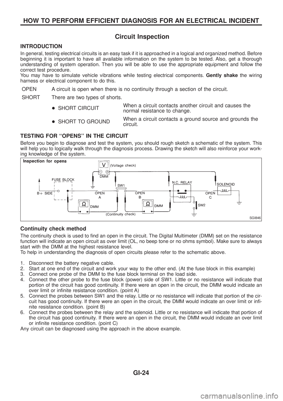
Before you begin to diagnose and test the system, you should rough sketch a schematic of the system. This
will help you to logically walk through the diagnosis process. Drawing the sketch will also reinforce your work-
ing knowledge of the system.
Continuity check method
The continuity check is used to ®nd an open in the circuit. The Digital Multimeter (DMM) set on the resistance
function will indicate an open circuit as over limit (OL, no beep tone or no ohms symbol). Make sure to always
start with the DMM at the highest resistance level.
To help in understanding the diagnosis of open circuits please refer to the schematic above.
1. Disconnect the battery negative cable.
2. Start at one end of the circuit and work your way to the other end. (At the fuse block in this example)
3. Connect one probe of the DMM to the fuse block terminal on the load side.
4. Connect the other probe to the fuse block (power) side of SW1. Little or no resistance will indicate that
portion of the circuit has good continuity. If there were an open in the circuit, the DMM would indicate an
over limit or in®nite resistance condition. (point A)
5. Connect the probes between SW1 and the relay. Little or no resistance will indicate that portion of the cir-
cuit has good continuity. If there were an open in the circuit, the DMM would indicate an over limit or in®-
nite resistance condition. (point B)
6. Connect the probes between the relay and the solenoid. Little or no resistance will indicate that portion of
the circuit has good continuity. If there were an open in the circuit, the DMM would indicate an over limit
or in®nite resistance condition. (point C)
Any circuit can be diagnosed using the approach in the above example.
SGI846
HOW TO PERFORM EFFICIENT DIAGNOSIS FOR AN ELECTRICAL INCIDENT
GI-24
Page 949 of 1226
A
A/C HFC134a (R134a) system service
procedure ..................................................HA-112
A/C HFC134a system service equip-
ment precaution ............................................HA-9
A/C air ¯ow .....................................................HA-13
A/C component layout ....................................HA-12
A/C compressor precaution..............................HA-6
A/C compressor special service tool ...........HA-6, 7
A/C control linkage adjustment (auto
A/C).............................................................HA-77
A/C control operation (manual A/C) ...............HA-16
A/C harness layout (manual A/C) ..................HA-17
A/C lubricant (R134a) ...................................HA-114
A/C relay.........................................................HA-97
A/C self-diagnoses (auto A/C)........................HA-63
A/CCUT - Wiring diagram ............................EC-186
A/T control ....................................................EC-174
ABS sensor rotor ............................................FA-15
ACC/SW - Wiring diagram ...........................EC-105
ACL/SW - Wiring diagram ............................EC-164
ADJRES - Wiring diagram .............................EC-91
APS - Wiring diagram ..................................EC-138
AT/C - Wiring diagram..................................EC-174
AUDIO - Wiring diagram ...............................EL-168
Accelerator position sensor ..........................EC-138
Accelerator position switch...........................EC-164
Accelerator switch (F/C) ...............................EC-105
Adjustment resistor.........................................EC-91
Air bag disposal..............................................RS-17
Air bag ..............................................................RS-8
Air bleeding (hydraulic clutch) ..........................CL-6
Air bleeding for brake system ..........................BR-4
Air cleaner ®lter replacement .........................MA-18
Air conditioner cut control ..............................EC-19
Air ¯ow meter - See Mass air ¯ow
sensor .........................................................EC-73
Air mix door control linkage
adjustment ................................................HA-81
Alternator.........................................................EL-56
Antenna - See Power antenna .....................EL-181
Audio and A/C control removal and
installation - See Instrument panel .............BT-11
Audio .............................................................EL-168
Auto lock free running hub .............................FA-13
Automatic ampli®er .........................................HA-61
Axle housing (rear) ...........................................RA-9
B
BACK/L - Wiring diagram................................EL-78
Back door opener - See Back door ..................BT-6
Back door trim.................................................BT-24
Back door window...........................................BT-45
Back door ..........................................................BT-6Back-up lamp switch (M/T) ..............................MT-4
Back-up lamp ..................................................EL-78
Battery .............................................................EL-37
Baulk ring (M/T)..............................................MT-10
Body alignment ...............................................BT-49
Body mounting ................................................BT-48
Brake booster .................................................BR-15
Brake ¯uid change ...........................................BR-3
Brake ¯uid level and line check .......................BR-3
Brake ¯uid level .............................................MA-23
Brake hydraulic line ..........................................BR-5
Brake inspection ............................................MA-24
Brake master cylinder ....................................BR-12
Brake pedal ....................................................BR-10
Bulb speci®cations ........................................EL-314
Bumper, front ................................................... BT-4
Bumper, rear .....................................................BT-6
C
CD/CHG - Wiring diagram ............................EL-176
CHIME - Wiring diagram...............................EL-136
CIGAR - Wiring diagram ...............................EL-156
CKPS - Wiring diagram ................................EC-143
CLOCK - Wiring diagram ..............................EL-157
CMPS - Wiring diagram .................................EC-68
COMPAS - Wiring diagram ...........................EL-117
CONSULT for ECCS ......................................EC-36
CONSULT general information ........................GI-33
COOL/F - Wiring diagram ............................EC-112
CSPS - Wiring diagram ..................................EC-86
Cab body.........................................................BT-47
Camshaft inspection ......................................EM-36
Camshaft position sensor (PUMP).................EC-68
Center case (Transfer) ....................................TF-10
Charge air cooler fan control .......................EC-177
Charge air temperature sensor ....................EC-121
Chassis and body maintenance ....................MA-20
Cigarette lighter.............................................EL-156
Circuit breaker.................................................EL-14
Clock .............................................................EL-157
Clutch booster...................................................CL-9
Clutch cover ....................................................CL-14
Clutch damper ..................................................CL-7
Clutch disc ......................................................CL-13
Clutch ¯uid level.............................................MA-20
Clutch master cylinder ......................................CL-7
Clutch operating cylinder ..................................CL-8
Clutch pedal ......................................................CL-5
Clutch release bearing ....................................CL-11
Clutch release mechanism .............................CL-11
Clutch withdrawal lever ...................................CL-11
Coil spring (front) ............................................FA-25
Coil spring (rear) ............................................RA-14
Collision diagnosis..........................................RS-45
Combination meter removal and instal-
lation - See Instrument panel ......................BT-11
ALPHABETICAL INDEX
IDX-2
Page 1146 of 1226
![NISSAN PATROL 2006 Service Manual HOW TO ERASE SELF-DIAGNOSIS RESULTS
With CONSULT
+``SELF-DIAG [CURRENT]
A current Self-diagnosis result is displayed on the CONSULT screen in real time. After the malfunction is
repaired completely,](/manual-img/5/57368/w960_57368-1145.png "NISSAN PATROL 2006 Service Manual HOW TO ERASE SELF-DIAGNOSIS RESULTS
With CONSULT
+``SELF-DIAG [CURRENT]
A current Self-diagnosis result is displayed on the CONSULT screen in real time. After the malfunction is
repaired completely,")
HOW TO ERASE SELF-DIAGNOSIS RESULTS
With CONSULT
+``SELF-DIAG [CURRENT]''
A current Self-diagnosis result is displayed on the CONSULT screen in real time. After the malfunction is
repaired completely, no malfunction is detected on ``SELF-DIAG [CURRENT]''.
+``SELF-DIAG [PAST]''
Return to the ``SELF-DIAG [CURRENT]'' CONSULT screen by
pushing ``BACK'' key of CONSULT and select ``SELF-DIAG
[CURRENT]'' in ``SELECT DIAG MODE''. Touch ``ERASE'' in
``SELF-DIAG [CURRENT]'' mode.
NOTE:
If the memory of the malfunction in ``SELF-DIAG [PAST]'' is not
erased, the User mode shows the system malfunction by the
operation of the warning lamp even if the malfunction is
repaired completely.
+``TROUBLE DIAG RECORD''
The memory of ``TROUBLE DIAG RECORD'' cannot be erased.
Without CONSULT
After a malfunction is repaired, return to User mode from Diagnosis mode by switching the ignition ``OFF'' for
at least 1 second, then back ``ON''. At that time, the problem code is cleared.
How to Perform Trouble Diagnoses for Quick
and Accurate Repair
A good understanding of the malfunction conditions can make troubleshooting faster and more accurate.
In general, each customer feels differently about a problem. It is important to fully understand the symptoms
or conditions for a customer complaint.
INFORMATION FROM CUSTOMER
WHAT ............ Vehicle model
WHEN ........... Date, Frequencies
WHERE ......... Road conditions
HOW .............. Operating conditions, Symptoms
PRELIMINARY CHECK
Check that the following parts are in good order.
+Battery [Refer to EL section (``BATTERY'').]
+Fuse [Refer to EL section (``Fuse'', ``POWER SUPPLY ROUTING'').]
+System component-to-harness connections
SRS357
TROUBLE DIAGNOSES Ð Supplemental Restraint System (SRS)
Trouble Diagnoses Introduction (Cont'd)
RS-24
Page 1170 of 1226
Supplemental Restraint System (SRS) ``AIR
BAG'' and ``SEAT BELT PRE-TENSIONER''
The Supplemental Restraint System such as ``AIR BAG'' and ``SEAT BELT PRE-TENSIONER'' used along with
a seat belt, helps to reduce the risk or severity of injury to the driver and front passenger in a frontal collision.
The SRS system composition which is available to NISSAN MODEL Y61 is as follows (The composition var-
ies according to the destination.):
Driver air bag module (located in the center of the steering wheel), front passenger air bag module (located
on the instrument panel on passenger side), seat belt pre-tensioner, a diagnosis sensor unit, warning lamp,
wiring harness and spiral cable.
Information necessary to service the system safely is included in theRS sectionof this Service Manual.
WARNING:
+To avoid rendering the SRS inoperative, which could increase the risk of personal injury or death
in the event of a collision which would result in air bag in¯ation, all maintenance must be performed
by an authorized NISSAN dealer.
+Improper maintenance, including incorrect removal and installation of the SRS, can lead to per-
sonal injury caused by unintentional activation of the system. For removal of Spiral Cable and Air
Bag Module, see the RS section.
+Do not use electrical test equipment on any circuit related to the SRS unless instructed to in this
Service Manual. Spiral cable and wiring harnesses covered with yellow insulation either just before
the harness connectors or for the complete harness are related to the SRS.
Precautions for Steering System
+Before disassembly, thoroughly clean the outside of the unit.
+Disassembly should be done in a clean work area. It is important to prevent the internal parts from
becoming contaminated by dirt or other foreign matter.
+Place disassembled parts in order, on a parts rack, for easier and proper assembly.
+Use nylon cloths or paper towels to clean the parts; common shop rags can leave lint that might
interfere with their operation.
+Before inspection or reassembly, carefully clean all parts with a general purpose, non-¯ammable
solvent.
+Before assembly, apply a coat of recommended ATF* to hydraulic parts. Vaseline may be applied
to O-rings and seals. Do not use any grease.
+Replace all gaskets, seals and O-rings. Avoid damaging O-rings, seals and gaskets during instal-
lation. Perform functional tests whenever designated.
*: Automatic Transmission Fluid type DEXRON
TMIII or equivalent
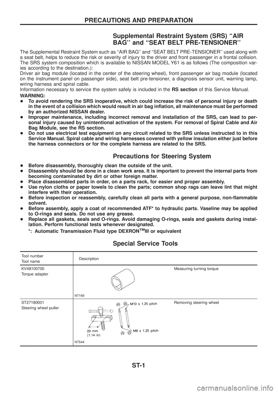
Special Service Tools
Tool number
Tool nameDescription
KV48100700
Torque adapter
NT169
Measuring turning torque
ST27180001
Steering wheel puller
NT544
Removing steering wheel
PRECAUTIONS AND PREPARATION
ST-1