2006 NISSAN PATROL relay
[x] Cancel search: relayPage 883 of 1226
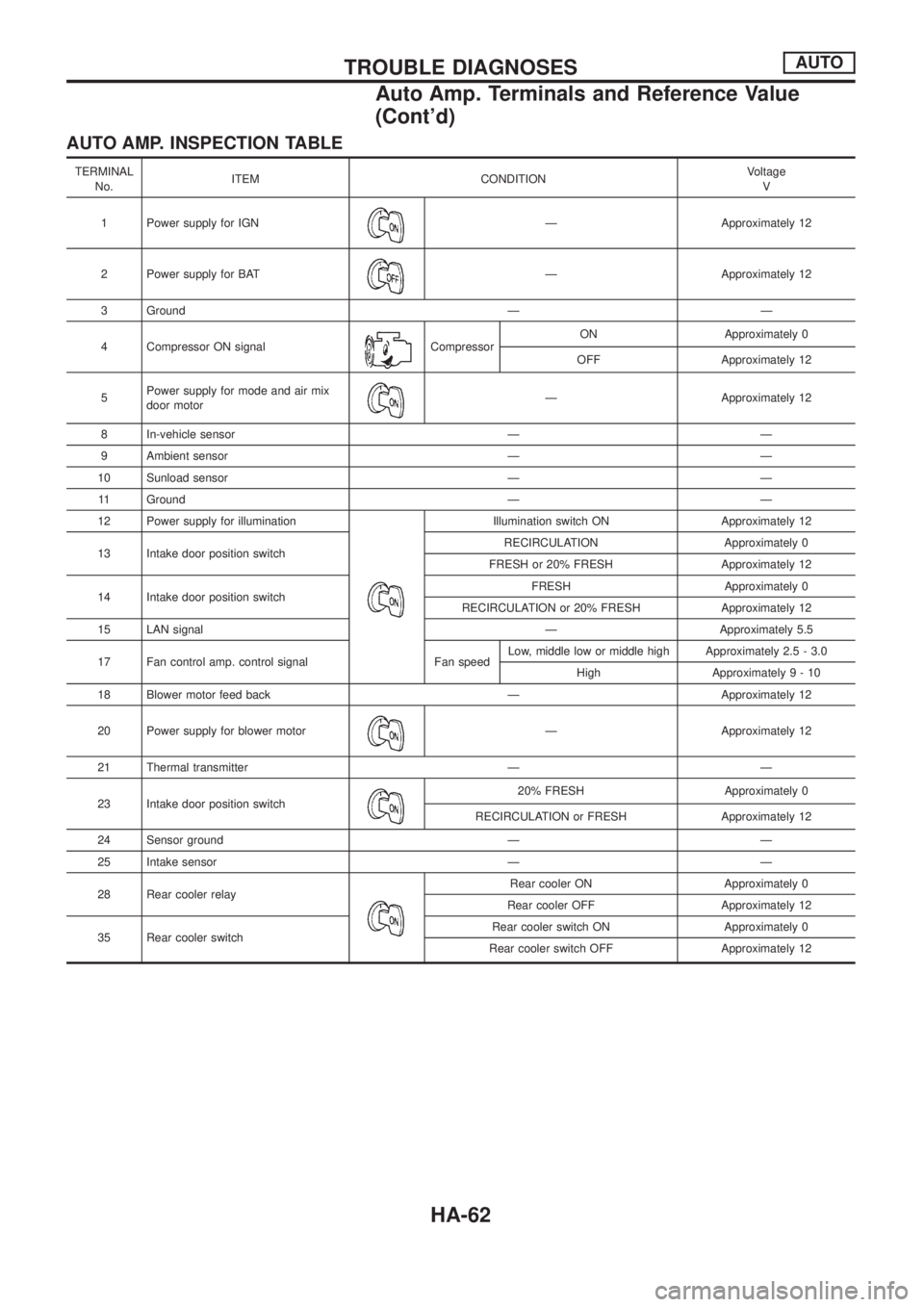
AUTO AMP. INSPECTION TABLE
TERMINAL
No.ITEM CONDITIONVoltage
V
1 Power supply for IGN
Ð Approximately 12
2 Power supply for BAT
Ð Approximately 12
3 Ground Ð Ð
4 Compressor ON signal
CompressorON Approximately 0
OFF Approximately 12
5Power supply for mode and air mix
door motor
Ð Approximately 12
8 In-vehicle sensor Ð Ð
9 Ambient sensor Ð Ð
10 Sunload sensor Ð Ð
11 Ground Ð Ð
12 Power supply for illumination
Illumination switch ON Approximately 12
13 Intake door position switchRECIRCULATION Approximately 0
FRESH or 20% FRESH Approximately 12
14 Intake door position switchFRESH Approximately 0
RECIRCULATION or 20% FRESH Approximately 12
15 LAN signal Ð Approximately 5.5
17 Fan control amp. control signal Fan speedLow, middle low or middle high Approximately 2.5 - 3.0
High Approximately9-10
18 Blower motor feed back Ð Approximately 12
20 Power supply for blower motor
Ð Approximately 12
21 Thermal transmitter Ð Ð
23 Intake door position switch
20% FRESH Approximately 0
RECIRCULATION or FRESH Approximately 12
24 Sensor ground Ð Ð
25 Intake sensor Ð Ð
28 Rear cooler relay
Rear cooler ON Approximately 0
Rear cooler OFF Approximately 12
35 Rear cooler switchRear cooler switch ON Approximately 0
Rear cooler switch OFF Approximately 12
TROUBLE DIAGNOSESAUTO
Auto Amp. Terminals and Reference Value
(Cont'd)
HA-62
Page 915 of 1226
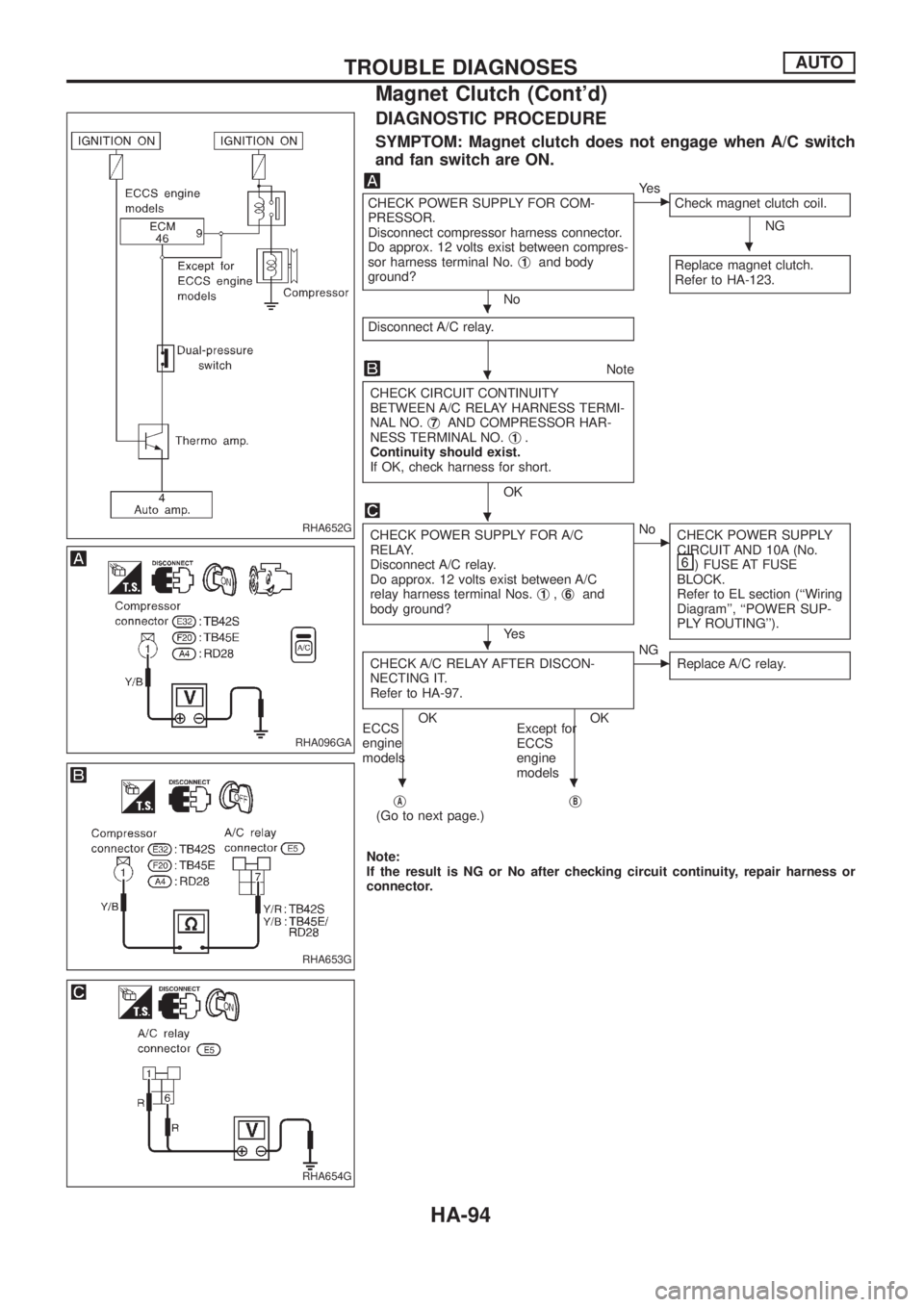
DIAGNOSTIC PROCEDURE
SYMPTOM: Magnet clutch does not engage when A/C switch
and fan switch are ON.
CHECK POWER SUPPLY FOR COM-
PRESSOR.
Disconnect compressor harness connector.
Do approx. 12 volts exist between compres-
sor harness terminal No.j
1and body
ground?
No
cYe s
Check magnet clutch coil.
NG
Replace magnet clutch.
Refer to HA-123.
Disconnect A/C relay.
Note
CHECK CIRCUIT CONTINUITY
BETWEEN A/C RELAY HARNESS TERMI-
NAL NO.j
7AND COMPRESSOR HAR-
NESS TERMINAL NO.j1.
Continuity should exist.
If OK, check harness for short.
OK
CHECK POWER SUPPLY FOR A/C
RELAY.
Disconnect A/C relay.
Do approx. 12 volts exist between A/C
relay harness terminal Nos.j
1,j6and
body ground?
Ye s
cNo
CHECK POWER SUPPLY
CIRCUIT AND 10A (No.
) FUSE AT FUSE
BLOCK.
Refer to EL section (``Wiring
Diagram'', ``POWER SUP-
PLY ROUTING'').
CHECK A/C RELAY AFTER DISCON-
NECTING IT.
Refer to HA-97.
OK OK
ECCS
engine
modelsExcept for
ECCS
engine
models
cNG
Replace A/C relay.
jA(Go to next page.)jB
Note:
If the result is NG or No after checking circuit continuity, repair harness or
connector.
RHA652G
RHA096GA
RHA653G
RHA654G
.
.
.
.
.
..
TROUBLE DIAGNOSESAUTO
Magnet Clutch (Cont'd)
HA-94
Page 916 of 1226

jA
Reconnect A/C relay.
CHECK COIL SIDE CIRCUIT OF A/C
RELAY.
Do approx. 12 volts exist between ECM
(ECCS control module) harness terminal
No.j
9and body ground?
Ye s
cNo
Disconnect A/C relay.
Disconnect ECM (ECCS
control module) harness
connector.
Note
CHECK CIRCUIT CONTI-
NUITY BETWEEN A/C
RELAY HARNESS TERMI-
NAL NO.j
2AND ECM
(ECCS CONTROL MOD-
ULE) HARNESS TERMI-
NAL NO.j
9.
Continuity should exist.
If OK, check harness for
short.
CHECK VOLTAGE FOR ECM (ECCS con-
trol module).
Do approx. 12 volts exist between ECM
(ECCS control module) harness terminal
No.j
46and body ground?
Ye s
cNo
CHECK ECM (ECCS con-
trol module). Refer to EC
section.
Disconnect ECM (ECCS control module)
harness connector.
Disconnect dual-pressure switch harness
connector.
Note
CHECK CIRCUIT CONTINUITY
BETWEEN ECM (ECCS CONTROL MOD-
ULE) HARNESS TERMINAL NO.j
46,j21
AND DUAL-PRESSURE SWITCH HAR-
NESS TERMINAL NO.j
2.
Continuity should exist.
If OK, check harness for short.
OK
CHECK DUAL-PRESSURE SWITCH.
Refer to HA-97.
OK
cNG
Replace dual-pressure
switch.
jC
Note:
If the result is NG or No after checking circuit continuity, repair harness
or connector.
RHA655G
RHA656G
RHA657G
RHA658G
.
.
.
.
.
.
.
.
TROUBLE DIAGNOSESAUTO
Magnet Clutch (Cont'd)
HA-95
Page 917 of 1226
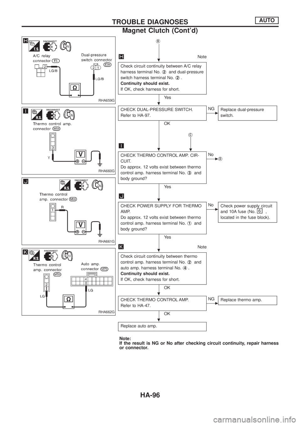
jB
Note
Check circuit continuity between A/C relay
harness terminal No.j
2and dual-pressure
switch harness terminal No.j
2.
Continuity should exist.
If OK, check harness for short.
Ye s
CHECK DUAL-PRESSURE SWITCH.
Refer to HA-97.
OK
cNG
Replace dual-pressure
switch.
jC
.
CHECK THERMO CONTROL AMP. CIR-
CUIT.
Do approx. 12 volts exist between thermo
control amp. harness terminal No.j
3and
body ground?
Ye s
cNo
jD
CHECK POWER SUPPLY FOR THERMO
AMP.
Do approx. 12 volts exist between thermo
control amp. harness terminal No.j
1and
body ground?
Ye s
cNo
Check power supply circuit
and 10A fuse (No.
,
located in the fuse block).
Note
Check circuit continuity between thermo
control amp. harness terminal No.j
2and
auto amp. harness terminal No.j
4.
Continuity should exist.
If OK, check harness for short.
OK
CHECK THERMO CONTROL AMP.
Refer to HA-47.
OK
cNG
Replace thermo amp.
Replace auto amp.
Note:
If the result is NG or No after checking circuit continuity, repair harness
or connector.
RHA659G
RHA660G
RHA661G
RHA662G
.
.
.
.
.
.
.
TROUBLE DIAGNOSESAUTO
Magnet Clutch (Cont'd)
HA-96
Page 918 of 1226
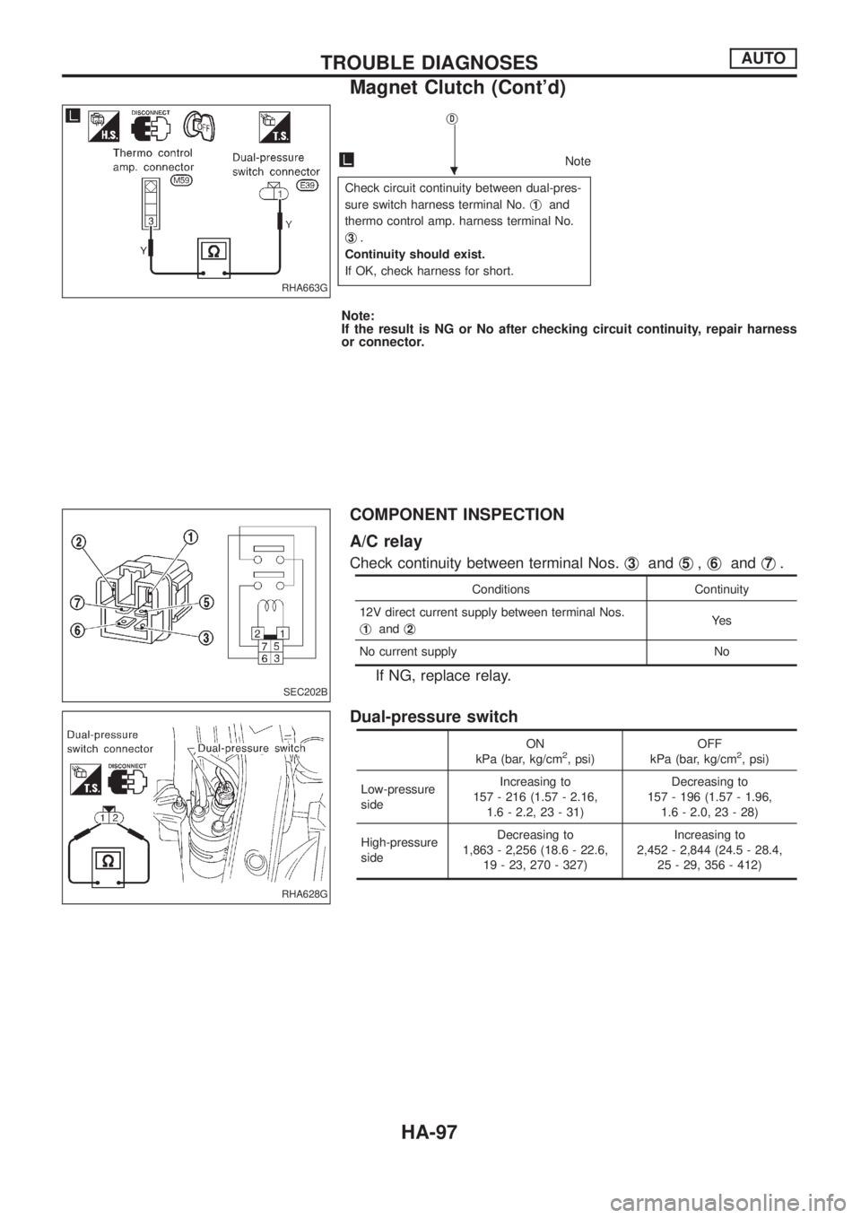
jD
Note
Check circuit continuity between dual-pres-
sure switch harness terminal No.j
1and
thermo control amp. harness terminal No.
j
3.
Continuity should exist.
If OK, check harness for short.
Note:
If the result is NG or No after checking circuit continuity, repair harness
or connector.
COMPONENT INSPECTION
A/C relay
Check continuity between terminal Nos.j3andj5,j6andj7.
Conditions Continuity
12V direct current supply between terminal Nos.
j
1andj2Ye s
No current supply No
If NG, replace relay.
Dual-pressure switch
ON
kPa (bar, kg/cm2, psi)OFF
kPa (bar, kg/cm2, psi)
Low-pressure
sideIncreasing to
157 - 216 (1.57 - 2.16,
1.6 - 2.2, 23 - 31)Decreasing to
157 - 196 (1.57 - 1.96,
1.6 - 2.0, 23 - 28)
High-pressure
sideDecreasing to
1,863 - 2,256 (18.6 - 22.6,
19 - 23, 270 - 327)Increasing to
2,452 - 2,844 (24.5 - 28.4,
25 - 29, 356 - 412)
RHA663G
SEC202B
RHA628G
.
TROUBLE DIAGNOSESAUTO
Magnet Clutch (Cont'd)
HA-97
Page 949 of 1226
A
A/C HFC134a (R134a) system service
procedure ..................................................HA-112
A/C HFC134a system service equip-
ment precaution ............................................HA-9
A/C air ¯ow .....................................................HA-13
A/C component layout ....................................HA-12
A/C compressor precaution..............................HA-6
A/C compressor special service tool ...........HA-6, 7
A/C control linkage adjustment (auto
A/C).............................................................HA-77
A/C control operation (manual A/C) ...............HA-16
A/C harness layout (manual A/C) ..................HA-17
A/C lubricant (R134a) ...................................HA-114
A/C relay.........................................................HA-97
A/C self-diagnoses (auto A/C)........................HA-63
A/CCUT - Wiring diagram ............................EC-186
A/T control ....................................................EC-174
ABS sensor rotor ............................................FA-15
ACC/SW - Wiring diagram ...........................EC-105
ACL/SW - Wiring diagram ............................EC-164
ADJRES - Wiring diagram .............................EC-91
APS - Wiring diagram ..................................EC-138
AT/C - Wiring diagram..................................EC-174
AUDIO - Wiring diagram ...............................EL-168
Accelerator position sensor ..........................EC-138
Accelerator position switch...........................EC-164
Accelerator switch (F/C) ...............................EC-105
Adjustment resistor.........................................EC-91
Air bag disposal..............................................RS-17
Air bag ..............................................................RS-8
Air bleeding (hydraulic clutch) ..........................CL-6
Air bleeding for brake system ..........................BR-4
Air cleaner ®lter replacement .........................MA-18
Air conditioner cut control ..............................EC-19
Air ¯ow meter - See Mass air ¯ow
sensor .........................................................EC-73
Air mix door control linkage
adjustment ................................................HA-81
Alternator.........................................................EL-56
Antenna - See Power antenna .....................EL-181
Audio and A/C control removal and
installation - See Instrument panel .............BT-11
Audio .............................................................EL-168
Auto lock free running hub .............................FA-13
Automatic ampli®er .........................................HA-61
Axle housing (rear) ...........................................RA-9
B
BACK/L - Wiring diagram................................EL-78
Back door opener - See Back door ..................BT-6
Back door trim.................................................BT-24
Back door window...........................................BT-45
Back door ..........................................................BT-6Back-up lamp switch (M/T) ..............................MT-4
Back-up lamp ..................................................EL-78
Battery .............................................................EL-37
Baulk ring (M/T)..............................................MT-10
Body alignment ...............................................BT-49
Body mounting ................................................BT-48
Brake booster .................................................BR-15
Brake ¯uid change ...........................................BR-3
Brake ¯uid level and line check .......................BR-3
Brake ¯uid level .............................................MA-23
Brake hydraulic line ..........................................BR-5
Brake inspection ............................................MA-24
Brake master cylinder ....................................BR-12
Brake pedal ....................................................BR-10
Bulb speci®cations ........................................EL-314
Bumper, front ................................................... BT-4
Bumper, rear .....................................................BT-6
C
CD/CHG - Wiring diagram ............................EL-176
CHIME - Wiring diagram...............................EL-136
CIGAR - Wiring diagram ...............................EL-156
CKPS - Wiring diagram ................................EC-143
CLOCK - Wiring diagram ..............................EL-157
CMPS - Wiring diagram .................................EC-68
COMPAS - Wiring diagram ...........................EL-117
CONSULT for ECCS ......................................EC-36
CONSULT general information ........................GI-33
COOL/F - Wiring diagram ............................EC-112
CSPS - Wiring diagram ..................................EC-86
Cab body.........................................................BT-47
Camshaft inspection ......................................EM-36
Camshaft position sensor (PUMP).................EC-68
Center case (Transfer) ....................................TF-10
Charge air cooler fan control .......................EC-177
Charge air temperature sensor ....................EC-121
Chassis and body maintenance ....................MA-20
Cigarette lighter.............................................EL-156
Circuit breaker.................................................EL-14
Clock .............................................................EL-157
Clutch booster...................................................CL-9
Clutch cover ....................................................CL-14
Clutch damper ..................................................CL-7
Clutch disc ......................................................CL-13
Clutch ¯uid level.............................................MA-20
Clutch master cylinder ......................................CL-7
Clutch operating cylinder ..................................CL-8
Clutch pedal ......................................................CL-5
Clutch release bearing ....................................CL-11
Clutch release mechanism .............................CL-11
Clutch withdrawal lever ...................................CL-11
Coil spring (front) ............................................FA-25
Coil spring (rear) ............................................RA-14
Collision diagnosis..........................................RS-45
Combination meter removal and instal-
lation - See Instrument panel ......................BT-11
ALPHABETICAL INDEX
IDX-2
Page 950 of 1226

Combination meter........................................EL-102
Combination switch .........................................EL-57
Combustion chamber replacement ................EM-32
Compass .......................................................EL-116
Compression pressure ...................................EM-10
Compressor special service tool ......................HA-6
Connecting rod...............................................EM-47
Connecting rod...............................................EM-51
Connector inspection .......................................GI-17
Console box - See Instrument panel ..............BT-11
Control lever (Transfer) .....................................TF-9
Control sleeve position sensor .......................EC-86
Coolant mixture ratio ......................................MA-11
Coolant replacement ......................................MA-14
Cooling circuit (engine) .....................................LC-9
Cooling fan control .......................................EC-112
Cooling fan motor .........................................EC-120
Cooling fan relay ..........................................EC-120
Cooling fan......................................................LC-15
Counter gear (M/T).........................................MT-10
Counter gear (Transfer) ..................................TF-11
Coupling sleeve (M/T) ....................................MT-10
Crankcase emission control system -
See Positive crankcase ventilation.............EC-21
Crankcase ventilation system - See
Positive crankcase ventilation ....................EC-21
Crankshaft position sensor (TDC)................EC-143
Crankshaft ......................................................EM-50
Cylinder block ..........................................EM-45, 48
Cylinder head .................................................EM-28
D
D/LOCK - Wiring diagram .............................EL-205
DEF - Wiring diagram ...................................EL-159
DEICER - Wiring diagram.............................EL-167
DTRL - Wiring diagram ...................................EL-67
Data link connector for Consult......................EC-36
Daytime light system.......................................EL-65
Diagnosis sensor unit .....................................RS-12
Diagnostic trouble code (DTC) for
ECCS OBD system ....................................EC-30
Differential carrier assembly...........................PD-31
Differential carrier disassembly ......................PD-14
Differential gear oil replacement ....................MA-22
Dimensions ......................................................GI-38
Dome light - See Interior lamp .......................EL-93
Door glass .........................................................BT-9
Door lock ...........................................................BT-9
Door mirror ......................................................BT-46
Door trim .........................................................BT-18
Door, front .........................................................BT-9
Door, rear ........................................................BT-10
Drive belt inspection ......................................MA-12
Drive chain (Transfer) .....................................TF-11
Drive pinion diff. inspection ............................PD-19
Drive pinion height .........................................PD-27
Drive shaft (front) ............................................FA-23
Dual pressure switch ......................................HA-11Dual pressure switch ......................................HA-97
E
ECCS basic inspection...................................EC-46
ECCS circuit diagram .....................................EC-11
ECCS component parts location ......................EC-8
ECCS on board diagnostic system ................EC-30
ECCS symptom matrix chart..........................EC-48
ECCS system diagram and chart ..................EC-12
ECCS-D control module .........................EC-54, 110
ECM input/output signal .................................EC-54
ECTS - Wiring diagram ..................................EC-78
EGR control (EGRC) - solenoid valve .........EC-155
EGR control valve ........................................EC-161
EGRC/V - Wiring diagram ............................EC-155
Electric governor ....................................EC-95, 148
Electric sunroof .............................................EL-186
Electrical diagnoses.........................................GI-20
Electrical unit.................................................EL-321
Electrical units location .................................EL-269
Electronic fuel injection pump ........................EC-27
Engine compartment .......................................BT-49
Engine coolant temperature sensor
(ECTS) ........................................................EC-78
Engine oil ®lter replacement ..........................MA-14
Engine oil precautions .......................................GI-4
Engine oil replacement ..................................MA-13
Engine outer component parts ........................EM-8
Engine removal ..............................................EM-43
Engine room - See Engine
compartment ...............................................BT-49
Engine serial number ......................................GI-37
Exhaust system inspection ............................MA-20
Exhaust system ................................................FE-3
Exterior ............................................................BT-26
F
FCUT - Wiring diagram ................................EC-129
FTS - Wiring diagram ...................................EC-134
Fan control amp. ............................................HA-88
Final drive disassembly ..................................PD-14
Final drive removal and installation................PD-11
Finisher, interior - See Trim ............................BT-14
Floor trim .........................................................BT-14
Flow charts ......................................................GI-30
Fluids................................................................MA-9
Flywheel (clutch).......................................CL-13, 14
Flywheel runout..............................................EM-52
Fog lamp, rear ................................................EL-80
Fork rod (M/T) ................................................MT-12
Front axle ........................................................FA-10
Front bumper ....................................................BT-4
Front case (Transfer) ......................................TF-10
Front disc brake .............................................BR-20
Front door .........................................................BT-9
ALPHABETICAL INDEX
IDX-3
Page 951 of 1226

Front drive shaft (Transfer) .............................TF-11
Front ®nal drive disassembly (4WD) ..............PD-14
Front ®nal drive removal and installa-
tion (4WD)...................................................PD-11
Front passenger air bag.............................RS-8, 14
Front seat belt ..................................................RS-2
Front seat ........................................................BT-32
Front suspension ............................................FA-24
Front washer .................................................EL-141
Front wiper ....................................................EL-141
Fuel cut control (at no load & high
engine speed) .............................................EC-20
Fuel cut solenoid valve ................................EC-129
Fuel ®ller lid.......................................................BT-6
Fuel ®lter replacement ...................................MA-16
Fuel gauge ....................................................EL-102
Fuel injection system......................................EC-15
Fuel line inspection ........................................MA-17
Fuel precautions ................................................GI-5
Fuel temperature sensor ..............................EC-134
Fuse block.....................................................EL-319
Fuse ................................................................EL-14
Fusible link ......................................................EL-14
G
GLOW - Wiring diagram...............................EC-150
GOVNR - Wiring diagram ..............................EC-95
Garage jack and safety stand .........................GI-39
Gauges..........................................................EL-102
Gear components (M/T) .................................MT-10
Glass .................................................................BT-9
Glow plug .............................................EC-150, 154
Glow relay ............................................EC-150, 154
Grease .............................................................MA-9
Ground distribution..........................................EL-15
H
H/AIM - Wiring diagram ..................................EL-71
H/LAMP - Wiring diagram ...............................EL-61
HEAT UP - Wiring diagram ..........................EC-182
HFC134a (R134a) system service
procedure ..................................................HA-112
HLC - Wiring diagram ...................................EL-153
HORN - Wiring diagram................................EL-155
Harness connector inspection .........................GI-17
Harness connector ............................................EL-2
Harness layout ..............................................EL-275
Headlamp aiming control ................................EL-70
Headlamp leveler - See Headlamp
aiming control ..............................................EL-70
Headlamp wiper ............................................EL-153
Headlamp ........................................................EL-61
Headlining - See Roof trim .............................BT-20
Heat up switch..............................................EC-182
Heated seat.....................................................BT-34Hood..................................................................BT-4
Horn ..............................................................EL-155
How to erase DTC for ECCS OBD
system ........................................................EC-30
I
IATS - Wiring diagram ..................................EC-121
IC/FAN - Wiring diagram ..............................EC-177
ILL - Wiring diagram .......................................EL-87
INT/L - Wiring diagram..................................EL-101
Identi®cation plate............................................GI-37
Idle speed inspection .....................................MA-19
Idle speed .......................................................EC-46
Illumination ......................................................EL-86
In vehicle sensor ..........................................HA-105
Injection nozzle inspection .............................MA-18
Injection nozzle...............................................EC-22
Injection timing control valve ........................EC-100
Instrument panel .............................................BT-11
Intake door control linkage adjustment ..........HA-84
Intake door motor ...........................................HA-25
Intake sensor ................................................HA-111
Interior lamp ....................................................EL-93
Interior .............................................................BT-14
J
Jacking points ..................................................GI-39
Joint connector (J/C).....................................EL-322
Journal bearing assembly (propeller
shaft) .............................................................PD-8
Journal bearing disassembly (propeller
shaft) .............................................................PD-7
Junction box (J/B) .........................................EL-319
L
LSV (Load sensing valve) ................................BR-6
Lifting points ....................................................GI-40
Limited slip diff. adjustment............................PD-23
Limited slip diff. assembly ..............................PD-24
Limited slip diff. disassembly .........................PD-21
Limited slip diff. inspection .............................PD-21
Location of electrical units ............................EL-269
Lock, door .........................................................BT-9
Lubricant (R134a) A/C ..................................HA-114
Lubricants.........................................................MA-9
Lubrication circuit (engine) ...............................LC-3
Lubrication-locks, hinges and hood
latches ........................................................MA-27
Luggage compartment trim .............................BT-14
Luggage room lamp ........................................EL-93
ALPHABETICAL INDEX
IDX-4