Page 996 of 1226
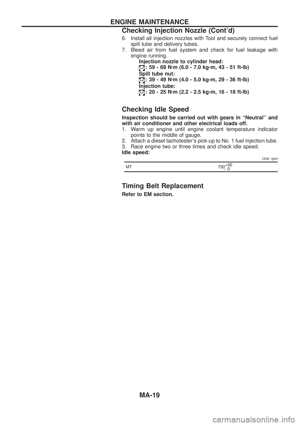
6. Install all injection nozzles with Tool and securely connect fuel
spill tube and delivery tubes.
7. Bleed air from fuel system and check for fuel leakage with
engine running.
Injection nozzle to cylinder head:
:59-69Nzm (6.0 - 7.0 kg-m, 43 - 51 ft-lb)
Spill tube nut:
:39-49Nzm (4.0 - 5.0 kg-m, 29 - 36 ft-lb)
Injection tube:
:20-25Nzm (2.2 - 2.5 kg-m, 16 - 18 ft-lb)
Checking Idle Speed
Inspection should be carried out with gears in ``Neutral'' and
with air conditioner and other electrical loads off.
1. Warm up engine until engine coolant temperature indicator
points to the middle of gauge.
2. Attach a diesel tachotester's pick-up to No. 1 fuel injection tube.
3. Race engine two or three times and check idle speed.
Idle speed:
Unit: rpm
MT 750+50
þ0
Timing Belt Replacement
Refer to EM section.
ENGINE MAINTENANCE
Checking Injection Nozzle (Cont'd)
MA-19
Page 1006 of 1226
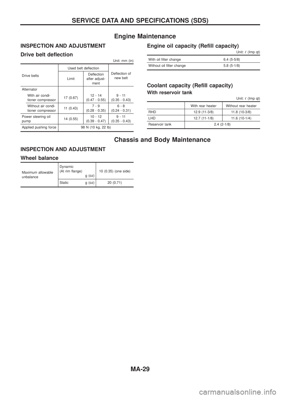
Engine Maintenance
INSPECTION AND ADJUSTMENT
Drive belt de¯ection
Unit: mm (in)
Drive beltsUsed belt de¯ection
De¯ection of
new belt
LimitDe¯ection
after adjust-
ment
Alternator
With air condi-
tioner compressor17 (0.67)12-14
(0.47 - 0.55)9-11
(0.35 - 0.43)
Without air condi-
tioner compressor11 (0.43)7-9
(0.28 - 0.35)6-8
(0.24 - 0.31)
Power steering oil
pump14 (0.55)10-12
(0.39 - 0.47)9-11
(0.35 - 0.43)
Applied pushing force 98 N (10 kg, 22 lb)
Engine oil capacity (Re®ll capacity)
Unit:!(Imp qt)
With oil ®lter change 6.4 (5-5/8)
Without oil ®lter change 5.8 (5-1/8)
Coolant capacity (Re®ll capacity)
With reservoir tank
Unit:!(Imp qt)
With rear heater Without rear heater
RHD 12.9 (11-3/8) 11.8 (10-3/8)
LHD 12.7 (11-1/8) 11.6 (10-1/4)
Reservoir tank 2.4 (2-1/8)
Chassis and Body Maintenance
INSPECTION AND ADJUSTMENT
Wheel balance
Maximum allowable
unbalanceDynamic
(At rim ¯ange)
g (oz)10 (0.35) (one side)
Static g (oz) 20 (0.71)
SERVICE DATA AND SPECIFICATIONS (SDS)
MA-29
Page 1097 of 1226
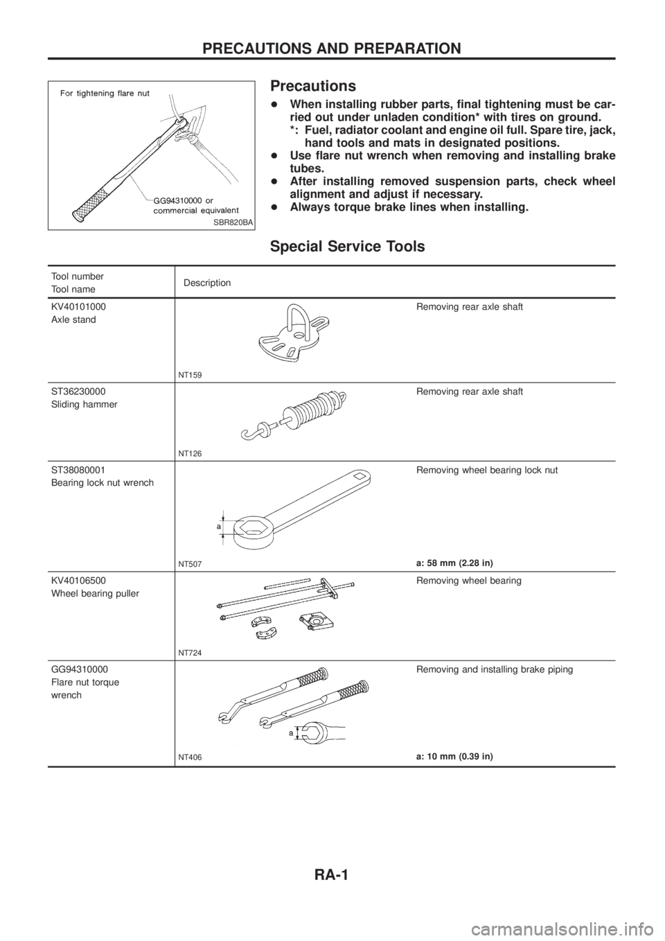
Precautions
+When installing rubber parts, ®nal tightening must be car-
ried out under unladen condition* with tires on ground.
*: Fuel, radiator coolant and engine oil full. Spare tire, jack,
hand tools and mats in designated positions.
+Use ¯are nut wrench when removing and installing brake
tubes.
+After installing removed suspension parts, check wheel
alignment and adjust if necessary.
+Always torque brake lines when installing.
Special Service Tools
Tool number
Tool nameDescription
KV40101000
Axle stand
NT159
Removing rear axle shaft
ST36230000
Sliding hammer
NT126
Removing rear axle shaft
ST38080001
Bearing lock nut wrench
NT507
Removing wheel bearing lock nut
a: 58 mm (2.28 in)
KV40106500
Wheel bearing puller
NT724
Removing wheel bearing
GG94310000
Flare nut torque
wrench
NT406
Removing and installing brake piping
a: 10 mm (0.39 in)
SBR820BA
PRECAUTIONS AND PREPARATION
RA-1