2006 NISSAN PATROL ECO mode
[x] Cancel search: ECO modePage 1158 of 1226
![NISSAN PATROL 2006 Service Manual 10. Check that no self-diagnostic failure is detected on ``SELF-
DIAG [PAST].
NOTE:
Past malfunction for seat belt pre-tensioner system will not be
displayed on ``SELF-DIAG [PAST].
11. Touch ``BAC](/manual-img/5/57368/w960_57368-1157.png "NISSAN PATROL 2006 Service Manual 10. Check that no self-diagnostic failure is detected on ``SELF-
DIAG [PAST].
NOTE:
Past malfunction for seat belt pre-tensioner system will not be
displayed on ``SELF-DIAG [PAST].
11. Touch ``BAC")
10. Check that no self-diagnostic failure is detected on ``SELF-
DIAG [PAST]''.
NOTE:
Past malfunction for seat belt pre-tensioner system will not be
displayed on ``SELF-DIAG [PAST]''.
11. Touch ``BACK'' key of CONSULT until ``SELECT SYSTEM''
appears in order to return to User mode from Diagnosis mode,
turn off CONSULT, then disconnect CONSULT.
12. Turn ignition switch ``OFF''.
13. Go to ``SRS Operation Check'', page RS-30 to check SRS
operation by using ``AIR BAG'' warning lamp with User mode.
DIAGNOSTIC PROCEDURE 4 (Continued from
DIAGNOSTIC PROCEDURE 2) (
with CONSULT)
Inspecting SRS malfunctioning record
Is it the ®rst time for maintenance of
SRS?
Ye s
cNo
Self-diagnostic failure
``SELF-DIAG [PAST]'' (pre-
viously stored in the
memory) might not be
erased after repair.
Go to DIAGNOSTIC PRO-
CEDURE 3, step 8 (RS-
34).
GO TO DIAGNOSTIC PROCEDURE 5
(RS-36).
DIAGNOSTIC PROCEDURE 5
Inspecting SRS intermittent problem by using CONSULT Ð
Diagnosis mode
1. Turn ignition switch ``OFF''.
2. Connect ``CONSULT'' to Data link connector.
3. Turn ignition switch ``ON''.
4. Touch ``START''.
SRS062
SRS468
SRS046
.
TROUBLE DIAGNOSES Ð Supplemental Restraint System (SRS)
Trouble Diagnoses with CONSULT (Cont'd)
RS-36
Page 1159 of 1226
![NISSAN PATROL 2006 Service Manual 5. Touch ``AIRBAG.
6. Touch ``SELF-DIAG [PAST].
7. If diagnostic codes are displayed on ``SELF-DIAG [PAST], go
to step 10.
If no self-diagnostic failure is detected on ``SELF-DIAG
[PAST], touc](/manual-img/5/57368/w960_57368-1158.png "NISSAN PATROL 2006 Service Manual 5. Touch ``AIRBAG.
6. Touch ``SELF-DIAG [PAST].
7. If diagnostic codes are displayed on ``SELF-DIAG [PAST], go
to step 10.
If no self-diagnostic failure is detected on ``SELF-DIAG
[PAST], touc")
5. Touch ``AIRBAG''.
6. Touch ``SELF-DIAG [PAST]''.
7. If diagnostic codes are displayed on ``SELF-DIAG [PAST]'', go
to step 10.
If no self-diagnostic failure is detected on ``SELF-DIAG
[PAST]'', touch ``BACK'' and go back to ``SELECT DIAG
MODE''.
NOTE:
Past malfunction for seat belt pre-tensioner system will not be
displayed on ``SELF-DIAG [PAST]''.
8. Touch ``TROUBLE DIAG RECORD''.
NOTE:
With ``TROUBLE DIAG RECORD'', diagnosis results previ-
ously erased by a reset operation can be displayed.
SRS074
SRS050
SRS054
SRS062
SRS055
TROUBLE DIAGNOSES Ð Supplemental Restraint System (SRS)
Trouble Diagnoses with CONSULT (Cont'd)
RS-37
Page 1160 of 1226
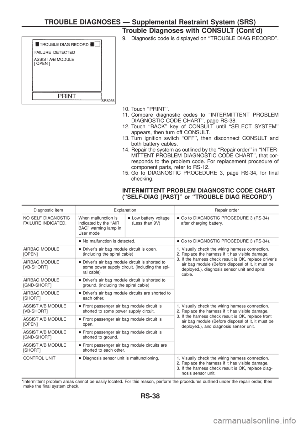
9. Diagnostic code is displayed on ``TROUBLE DIAG RECORD''.
10. Touch ``PRINT''.
11. Compare diagnostic codes to ``INTERMITTENT PROBLEM
DIAGNOSTIC CODE CHART'', page RS-38.
12. Touch ``BACK'' key of CONSULT until ``SELECT SYSTEM''
appears, then turn off CONSULT.
13. Turn ignition switch ``OFF'', then disconnect CONSULT and
both battery cables.
14. Repair the system as outlined by the ``Repair order'' in ``INTER-
MITTENT PROBLEM DIAGNOSTIC CODE CHART'', that cor-
responds to the problem code. For replacement procedure of
component parts, refer to RS-12.
15. Go to DIAGNOSTIC PROCEDURE 3, page RS-34, for ®nal
checking.
INTERMITTENT PROBLEM DIAGNOSTIC CODE CHART
(``SELF-DIAG [PAST]'' or ``TROUBLE DIAG RECORD'')
Diagnostic item Explanation Repair order
NO SELF DIAGNOSTIC
FAILURE INDICATED.When malfunction is
indicated by the ``AIR
BAG'' warning lamp in
User mode+Low battery voltage
(Less than 9V)+Go to DIAGNOSTIC PROCEDURE 3 (RS-34)
after charging battery.
+No malfunction is detected.+Go to DIAGNOSTIC PROCEDURE 3 (RS-34).
AIRBAG MODULE
[OPEN]+Driver's air bag module circuit is open.
(including the spiral cable)1. Visually check the wiring harness connection.
2. Replace the harness if it has visible damage.
3. If the harness check result is OK, replace driver's
air bag module (Before disposal of it, it must be
deployed.), diagnosis sensor unit and spiral
cable. AIRBAG MODULE
[VB-SHORT]+Driver's air bag module circuit is shorted to
some power supply circuit. (including the spi-
ral cable)
AIRBAG MODULE
[GND-SHORT]+Driver's air bag module circuit is shorted to
ground. (including the spiral cable)
AIRBAG MODULE
[SHORT]+Driver's air bag module circuits are shorted to
each other.
ASSIST A/B MODULE
[VB-SHORT]+Front passenger air bag module circuit is
shorted to some power supply circuit.1. Visually check the wiring harness connection.
2. Replace the harness if it has visible damage.
3. If the harness check result is OK, replace front
air bag module (Before disposal of it, it must be
deployed.), and diagnosis sensor unit. ASSIST A/B MODULE
[OPEN]+Front passenger air bag module circuit is
open.
ASSIST A/B MODULE
[GND-SHORT]+Front passenger air bag module circuit is
shorted to ground.
ASSIST A/B MODULE
[SHORT]+Front passenger air bag module circuits are
shorted to each other.
CONTROL UNIT+Diagnosis sensor unit is malfunctioning. 1. Visually check the wiring harness connection.
2. Replace the harness if it has visible damage.
3. If the harness check result is OK, replace diag-
nosis sensor unit.
*Intermittent problem areas cannot be easily located. For this reason, perform the procedures outlined under the repair order, then
make the ®nal system check.
SRS056
TROUBLE DIAGNOSES Ð Supplemental Restraint System (SRS)
Trouble Diagnoses with CONSULT (Cont'd)
RS-38
Page 1161 of 1226
Trouble Diagnoses without CONSULT
DIAGNOSTIC PROCEDURE 6
Inspecting SRS malfunctioning parts by using ``AIR BAG''
warning lamp Ð Diagnosis mode
NOTE:
SRS will not enter Diagnosis mode if no malfunction is
detected in User mode.
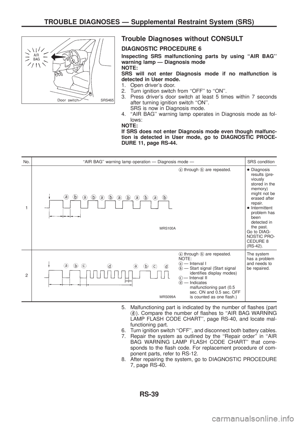
1. Open driver's door.
2. Turn ignition switch from ``OFF'' to ``ON''.
3. Press driver's door switch at least 5 times within 7 seconds
after turning ignition switch ``ON''.
SRS is now in Diagnosis mode.
4. ``AIR BAG'' warning lamp operates in Diagnosis mode as fol-
lows:
NOTE:
If SRS does not enter Diagnosis mode even though malfunc-
tion is detected in User mode, go to DIAGNOSTIC PROCE-
DURE 11, page RS-44.
No. ``AIR BAG'' warning lamp operation Ð Diagnosis mode Ð SRS condition
1
MRS100A
jathroughjbare repeated.+Diagnosis
results (pre-
viously
stored in the
memory)
might not be
erased after
repair.
+Intermittent
problem has
been
detected in
the past.
Go to DIAG-
NOSTIC PRO-
CEDURE 8
(RS-42).
2
MRS099A
jathroughjbare repeated.
NOTE:
j
aÐ Interval I
jbÐ Start signal (Start signal
identi®es display modes)
j
cÐ Interval II
jdÐ Indicates
malfunctioning part (0.5
sec. ON and 0.5 sec. OFF
is counted as one ¯ash.)The system
has a problem
and needs to
be repaired.
5. Malfunctioning part is indicated by the number of ¯ashes (part
j
d). Compare the number of ¯ashes to ``AIR BAG WARNING
LAMP FLASH CODE CHART'', page RS-40, and locate mal-
functioning part.
6. Turn ignition switch ``OFF'', and disconnect both battery cables.
7. Repair the system as outlined by the ``Repair order'' in ``AIR
BAG WARNING LAMP FLASH CODE CHART'' that corre-
sponds to the ¯ash code. For replacement procedure of com-
ponent parts, refer to RS-12.
8. After repairing the system, go to DIAGNOSTIC PROCEDURE
7, page RS-40.
SRS465
TROUBLE DIAGNOSES Ð Supplemental Restraint System (SRS)
RS-39
Page 1163 of 1226
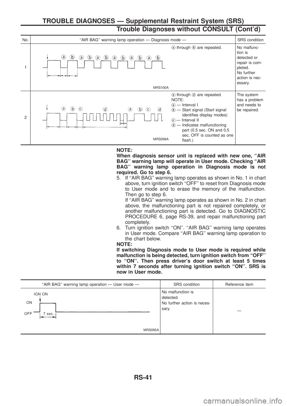
No. ``AIR BAG'' warning lamp operation Ð Diagnosis mode Ð SRS condition
1
MRS100A
jathroughjbare repeated. No malfunc-
tion is
detected or
repair is com-
pleted.
No further
action is nec-
essary.
2
MRS099A
jathroughjdare repeated.
NOTE:
j
aÐ Interval I
jbÐ Start signal (Start signal
identi®es display modes)
j
cÐ Interval II
jdÐ Indicates malfunctioning
part (0.5 sec. ON and 0.5
sec. OFF is counted as one
¯ash.)The system
has a problem
and needs to
be repaired.
NOTE:
When diagnosis sensor unit is replaced with new one, ``AIR
BAG'' warning lamp will operate in User mode. Checking ``AIR
BAG'' warning lamp operation in Diagnosis mode is not
required. Go to step 6.
5. If ``AIR BAG'' warning lamp operates as shown in No. 1 in chart
above, turn ignition switch ``OFF'' to reset from Diagnosis mode
to User mode and to erase the memory of the malfunction.
Then go to step 6.
If ``AIR BAG'' warning lamp operates as shown in No. 2 in chart
above, the malfunctioning part is not repaired completely, or
another malfunctioning part is detected. Go to DIAGNOSTIC
PROCEDURE 6, page RS-39, and repair malfunctioning part
completely.
6. Turn ignition switch ``ON''. ``AIR BAG'' warning lamp operates
in User mode. Compare ``AIR BAG'' warning lamp operation to
the chart below.
NOTE:
If switching Diagnosis mode to User mode is required while
malfunction is being detected, turn ignition switch from ``OFF''
to ``ON''. Then press driver's door switch at least 5 times
within 7 seconds after turning ignition switch ``ON''. SRS is
now in User mode.
``AIR BAG'' warning lamp operation Ð User mode Ð SRS condition Reference item
MRS095A
No malfunction is
detected.
No further action is neces-
sary.
Ð
TROUBLE DIAGNOSES Ð Supplemental Restraint System (SRS)
Trouble Diagnoses without CONSULT (Cont'd)
RS-41
Page 1164 of 1226
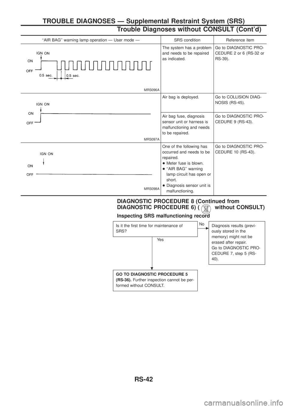
``AIR BAG'' warning lamp operation Ð User mode Ð SRS condition Reference item
MRS096A
The system has a problem
and needs to be repaired
as indicated.Go to DIAGNOSTIC PRO-
CEDURE 2 or 6 (RS-32 or
RS-39).
MRS097A
Air bag is deployed. Go to COLLISION DIAG-
NOSIS (RS-45).
Air bag fuse, diagnosis
sensor unit or harness is
malfunctioning and needs
to be repaired.Go to DIAGNOSTIC PRO-
CEDURE 9 (RS-43).
MRS098A
One of the following has
occurred and needs to be
repaired.
+Meter fuse is blown.
+``AIR BAG'' warning
lamp circuit has open or
short.
+Diagnosis sensor unit is
malfunctioning.Go to DIAGNOSTIC PRO-
CEDURE 10 (RS-43).
DIAGNOSTIC PROCEDURE 8 (Continued from
DIAGNOSTIC PROCEDURE 6) (
without CONSULT)
Inspecting SRS malfunctioning record
Is it the ®rst time for maintenance of
SRS?
Ye s
cNo
Diagnosis results (previ-
ously stored in the
memory) might not be
erased after repair.
Go to DIAGNOSTIC PRO-
CEDURE 7, step 5 (RS-
40).
GO TO DIAGNOSTIC PROCEDURE 5
(RS-36).Further inspection cannot be per-
formed without CONSULT.
.
TROUBLE DIAGNOSES Ð Supplemental Restraint System (SRS)
Trouble Diagnoses without CONSULT (Cont'd)
RS-42
Page 1170 of 1226
Supplemental Restraint System (SRS) ``AIR
BAG'' and ``SEAT BELT PRE-TENSIONER''
The Supplemental Restraint System such as ``AIR BAG'' and ``SEAT BELT PRE-TENSIONER'' used along with
a seat belt, helps to reduce the risk or severity of injury to the driver and front passenger in a frontal collision.
The SRS system composition which is available to NISSAN MODEL Y61 is as follows (The composition var-
ies according to the destination.):
Driver air bag module (located in the center of the steering wheel), front passenger air bag module (located
on the instrument panel on passenger side), seat belt pre-tensioner, a diagnosis sensor unit, warning lamp,
wiring harness and spiral cable.
Information necessary to service the system safely is included in theRS sectionof this Service Manual.
WARNING:
+To avoid rendering the SRS inoperative, which could increase the risk of personal injury or death
in the event of a collision which would result in air bag in¯ation, all maintenance must be performed
by an authorized NISSAN dealer.
+Improper maintenance, including incorrect removal and installation of the SRS, can lead to per-
sonal injury caused by unintentional activation of the system. For removal of Spiral Cable and Air
Bag Module, see the RS section.
+Do not use electrical test equipment on any circuit related to the SRS unless instructed to in this
Service Manual. Spiral cable and wiring harnesses covered with yellow insulation either just before
the harness connectors or for the complete harness are related to the SRS.
Precautions for Steering System
+Before disassembly, thoroughly clean the outside of the unit.
+Disassembly should be done in a clean work area. It is important to prevent the internal parts from
becoming contaminated by dirt or other foreign matter.
+Place disassembled parts in order, on a parts rack, for easier and proper assembly.
+Use nylon cloths or paper towels to clean the parts; common shop rags can leave lint that might
interfere with their operation.
+Before inspection or reassembly, carefully clean all parts with a general purpose, non-¯ammable
solvent.
+Before assembly, apply a coat of recommended ATF* to hydraulic parts. Vaseline may be applied
to O-rings and seals. Do not use any grease.
+Replace all gaskets, seals and O-rings. Avoid damaging O-rings, seals and gaskets during instal-
lation. Perform functional tests whenever designated.
*: Automatic Transmission Fluid type DEXRON
TMIII or equivalent
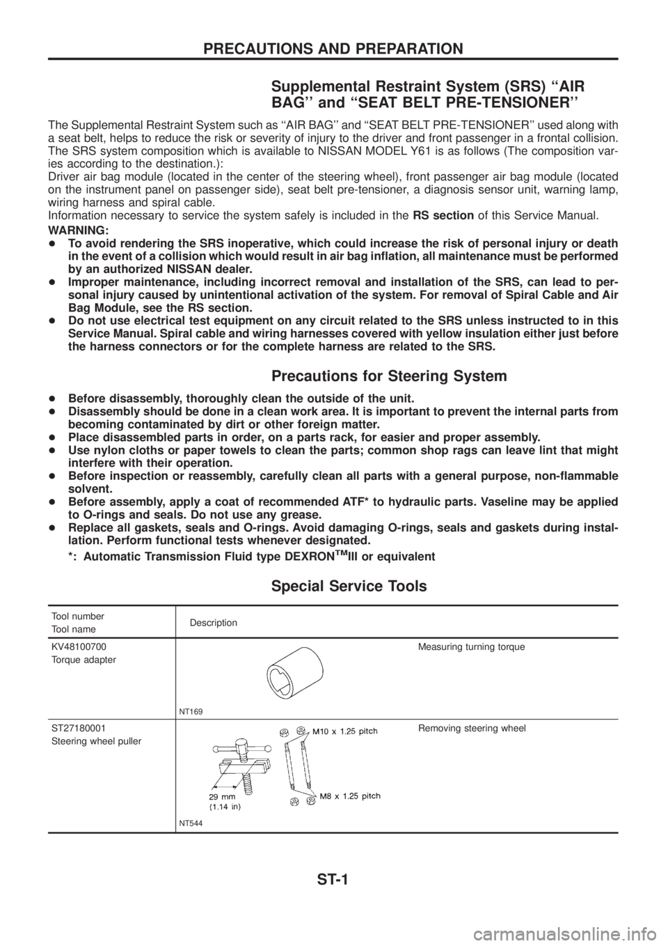
Special Service Tools
Tool number
Tool nameDescription
KV48100700
Torque adapter
NT169
Measuring turning torque
ST27180001
Steering wheel puller
NT544
Removing steering wheel
PRECAUTIONS AND PREPARATION
ST-1
Page 1201 of 1226
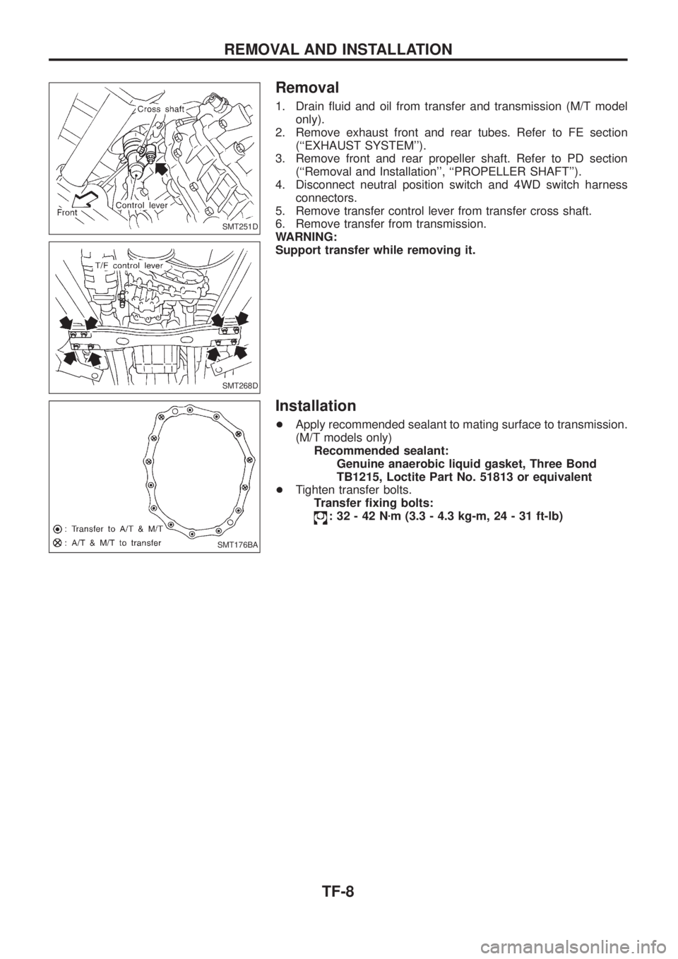
Removal
1. Drain ¯uid and oil from transfer and transmission (M/T model
only).
2. Remove exhaust front and rear tubes. Refer to FE section
(``EXHAUST SYSTEM'').
3. Remove front and rear propeller shaft. Refer to PD section
(``Removal and Installation'', ``PROPELLER SHAFT'').
4. Disconnect neutral position switch and 4WD switch harness
connectors.
5. Remove transfer control lever from transfer cross shaft.
6. Remove transfer from transmission.
WARNING:
Support transfer while removing it.
Installation
+Apply recommended sealant to mating surface to transmission.
(M/T models only)
Recommended sealant:
Genuine anaerobic liquid gasket, Three Bond
TB1215, Loctite Part No. 51813 or equivalent
+Tighten transfer bolts.
Transfer ®xing bolts:
:32-42Nzm (3.3 - 4.3 kg-m, 24 - 31 ft-lb)
SMT251D
SMT268D
SMT176BA
REMOVAL AND INSTALLATION
TF-8