Page 1158 of 1226
![NISSAN PATROL 2006 Service Manual 10. Check that no self-diagnostic failure is detected on ``SELF-
DIAG [PAST].
NOTE:
Past malfunction for seat belt pre-tensioner system will not be
displayed on ``SELF-DIAG [PAST].
11. Touch ``BAC NISSAN PATROL 2006 Service Manual 10. Check that no self-diagnostic failure is detected on ``SELF-
DIAG [PAST].
NOTE:
Past malfunction for seat belt pre-tensioner system will not be
displayed on ``SELF-DIAG [PAST].
11. Touch ``BAC](/manual-img/5/57368/w960_57368-1157.png)
10. Check that no self-diagnostic failure is detected on ``SELF-
DIAG [PAST]''.
NOTE:
Past malfunction for seat belt pre-tensioner system will not be
displayed on ``SELF-DIAG [PAST]''.
11. Touch ``BACK'' key of CONSULT until ``SELECT SYSTEM''
appears in order to return to User mode from Diagnosis mode,
turn off CONSULT, then disconnect CONSULT.
12. Turn ignition switch ``OFF''.
13. Go to ``SRS Operation Check'', page RS-30 to check SRS
operation by using ``AIR BAG'' warning lamp with User mode.
DIAGNOSTIC PROCEDURE 4 (Continued from
DIAGNOSTIC PROCEDURE 2) (
with CONSULT)
Inspecting SRS malfunctioning record
Is it the ®rst time for maintenance of
SRS?
Ye s
cNo
Self-diagnostic failure
``SELF-DIAG [PAST]'' (pre-
viously stored in the
memory) might not be
erased after repair.
Go to DIAGNOSTIC PRO-
CEDURE 3, step 8 (RS-
34).
GO TO DIAGNOSTIC PROCEDURE 5
(RS-36).
DIAGNOSTIC PROCEDURE 5
Inspecting SRS intermittent problem by using CONSULT Ð
Diagnosis mode
1. Turn ignition switch ``OFF''.
2. Connect ``CONSULT'' to Data link connector.
3. Turn ignition switch ``ON''.
4. Touch ``START''.
SRS062
SRS468
SRS046
.
TROUBLE DIAGNOSES Ð Supplemental Restraint System (SRS)
Trouble Diagnoses with CONSULT (Cont'd)
RS-36
Page 1160 of 1226

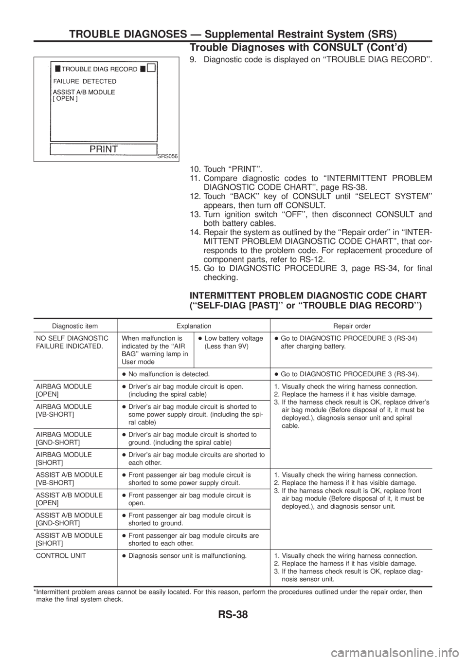
9. Diagnostic code is displayed on ``TROUBLE DIAG RECORD''.
10. Touch ``PRINT''.
11. Compare diagnostic codes to ``INTERMITTENT PROBLEM
DIAGNOSTIC CODE CHART'', page RS-38.
12. Touch ``BACK'' key of CONSULT until ``SELECT SYSTEM''
appears, then turn off CONSULT.
13. Turn ignition switch ``OFF'', then disconnect CONSULT and
both battery cables.
14. Repair the system as outlined by the ``Repair order'' in ``INTER-
MITTENT PROBLEM DIAGNOSTIC CODE CHART'', that cor-
responds to the problem code. For replacement procedure of
component parts, refer to RS-12.
15. Go to DIAGNOSTIC PROCEDURE 3, page RS-34, for ®nal
checking.
INTERMITTENT PROBLEM DIAGNOSTIC CODE CHART
(``SELF-DIAG [PAST]'' or ``TROUBLE DIAG RECORD'')
Diagnostic item Explanation Repair order
NO SELF DIAGNOSTIC
FAILURE INDICATED.When malfunction is
indicated by the ``AIR
BAG'' warning lamp in
User mode+Low battery voltage
(Less than 9V)+Go to DIAGNOSTIC PROCEDURE 3 (RS-34)
after charging battery.
+No malfunction is detected.+Go to DIAGNOSTIC PROCEDURE 3 (RS-34).
AIRBAG MODULE
[OPEN]+Driver's air bag module circuit is open.
(including the spiral cable)1. Visually check the wiring harness connection.
2. Replace the harness if it has visible damage.
3. If the harness check result is OK, replace driver's
air bag module (Before disposal of it, it must be
deployed.), diagnosis sensor unit and spiral
cable. AIRBAG MODULE
[VB-SHORT]+Driver's air bag module circuit is shorted to
some power supply circuit. (including the spi-
ral cable)
AIRBAG MODULE
[GND-SHORT]+Driver's air bag module circuit is shorted to
ground. (including the spiral cable)
AIRBAG MODULE
[SHORT]+Driver's air bag module circuits are shorted to
each other.
ASSIST A/B MODULE
[VB-SHORT]+Front passenger air bag module circuit is
shorted to some power supply circuit.1. Visually check the wiring harness connection.
2. Replace the harness if it has visible damage.
3. If the harness check result is OK, replace front
air bag module (Before disposal of it, it must be
deployed.), and diagnosis sensor unit. ASSIST A/B MODULE
[OPEN]+Front passenger air bag module circuit is
open.
ASSIST A/B MODULE
[GND-SHORT]+Front passenger air bag module circuit is
shorted to ground.
ASSIST A/B MODULE
[SHORT]+Front passenger air bag module circuits are
shorted to each other.
CONTROL UNIT+Diagnosis sensor unit is malfunctioning. 1. Visually check the wiring harness connection.
2. Replace the harness if it has visible damage.
3. If the harness check result is OK, replace diag-
nosis sensor unit.
*Intermittent problem areas cannot be easily located. For this reason, perform the procedures outlined under the repair order, then
make the ®nal system check.
SRS056
TROUBLE DIAGNOSES Ð Supplemental Restraint System (SRS)
Trouble Diagnoses with CONSULT (Cont'd)
RS-38
Page 1165 of 1226

Trouble Diagnoses: ``AIR BAG'' Warning Lamp
Does Not Turn Off
DIAGNOSTIC PROCEDURE 9
Is air bag deployed?
NocYe s
Refer to COLLISION DIAG-
NOSIS (RS-45).
Is SRS ``Air Bag'' fuse OK?
Ye scNo
Replace fuse.
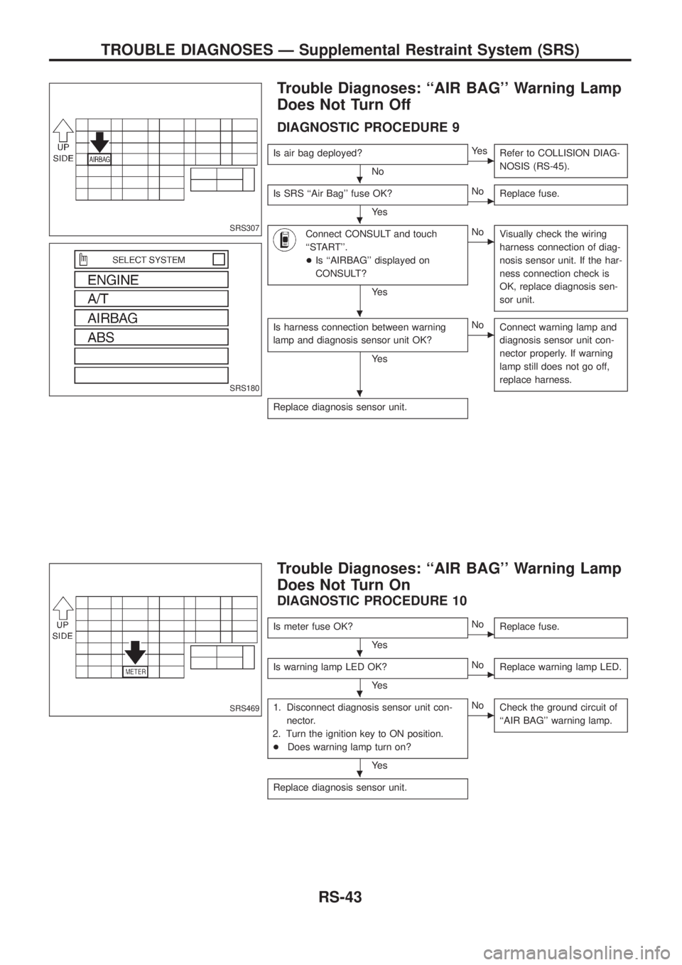
Connect CONSULT and touch
``START''.
+Is ``AIRBAG'' displayed on
CONSULT?
Ye s
cNo
Visually check the wiring
harness connection of diag-
nosis sensor unit. If the har-
ness connection check is
OK, replace diagnosis sen-
sor unit.
Is harness connection between warning
lamp and diagnosis sensor unit OK?
Ye s
cNo
Connect warning lamp and
diagnosis sensor unit con-
nector properly. If warning
lamp still does not go off,
replace harness.
Replace diagnosis sensor unit.
Trouble Diagnoses: ``AIR BAG'' Warning Lamp
Does Not Turn On
DIAGNOSTIC PROCEDURE 10
Is meter fuse OK?
Ye scNo
Replace fuse.
Is warning lamp LED OK?
Ye scNo
Replace warning lamp LED.
1. Disconnect diagnosis sensor unit con-
nector.
2. Turn the ignition key to ON position.
+Does warning lamp turn on?
Ye s
cNo
Check the ground circuit of
``AIR BAG'' warning lamp.
Replace diagnosis sensor unit.
SRS307
SRS180
SRS469
.
.
.
.
.
.
.
TROUBLE DIAGNOSES Ð Supplemental Restraint System (SRS)
RS-43
Page 1179 of 1226
Disassembly and Assembly
V1Combination switch
V2Lock nut
V3Jacket tube assembly
V4Tilt lever
V5Tilt spring
V6Steering column shaft assembly
V7Band
V8Column cover
V9Coupling
+When disassembling and assembling, unlock steering lock with
key.
+Install lock nut on steering column shaft and tighten the nut to
speci®cation.
: 25-34Nzm (2.5 - 3.5 kg-m, 18 - 25 ft-lb)
+Steering lock
a. Break self-shear type screws with a drill or other appropriate
tool.
b. Install new self-shear type screws and then cut off self-shear
type screw heads.
SST760C
SST490C
SST742A
STEERING WHEEL AND STEERING COLUMN
ST-10