2006 NISSAN PATROL key
[x] Cancel search: keyPage 610 of 1226
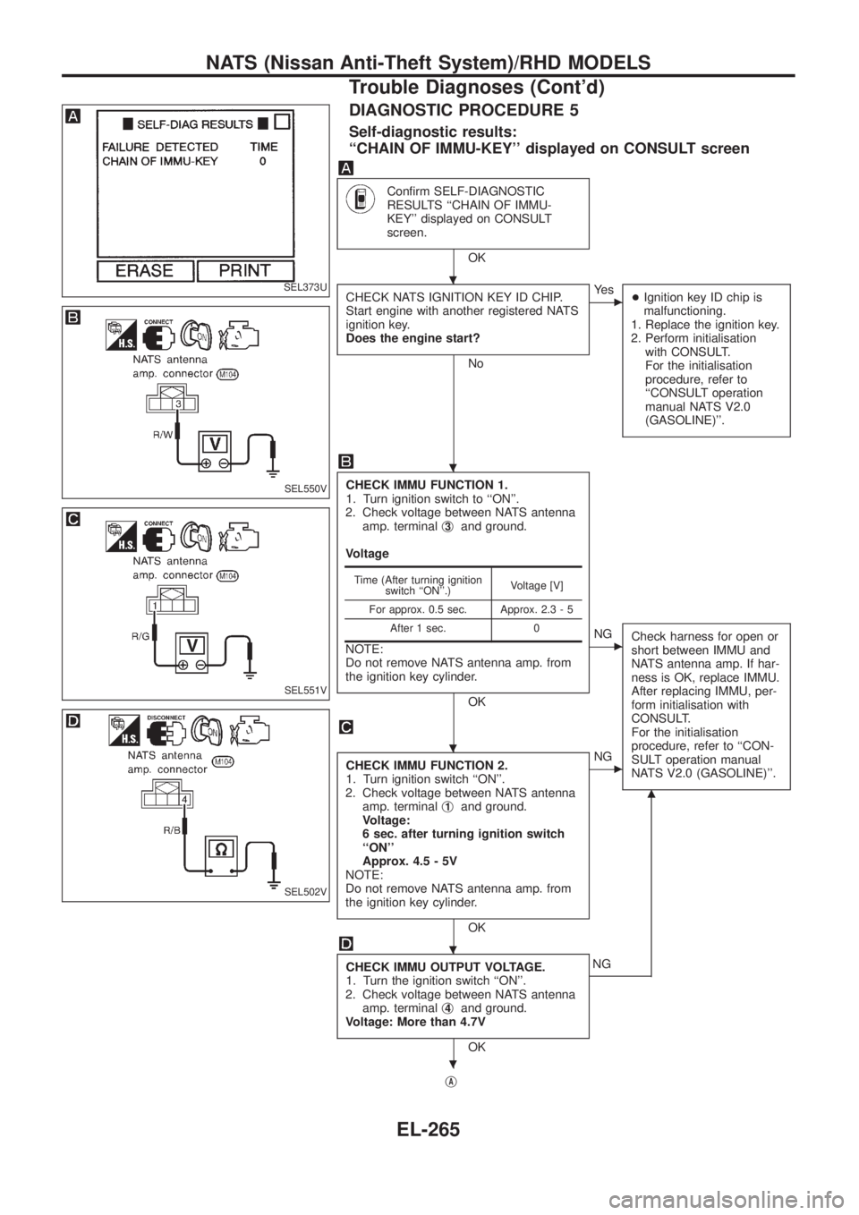
DIAGNOSTIC PROCEDURE 5
Self-diagnostic results:
``CHAIN OF IMMU-KEY'' displayed on CONSULT screen
Con®rm SELF-DIAGNOSTIC
RESULTS ``CHAIN OF IMMU-
KEY'' displayed on CONSULT
screen.
OK
CHECK NATS IGNITION KEY ID CHIP.
Start engine with another registered NATS
ignition key.
Does the engine start?
No
cYe s
+Ignition key ID chip is
malfunctioning.
1. Replace the ignition key.
2. Perform initialisation
with CONSULT.
For the initialisation
procedure, refer to
``CONSULT operation
manual NATS V2.0
(GASOLINE)''.
CHECK IMMU FUNCTION 1.
1. Turn ignition switch to ``ON''.
2. Check voltage between NATS antenna
amp. terminalj
3and ground.
Voltage
NOTE:
Do not remove NATS antenna amp. from
the ignition key cylinder.
OK
cNG
Check harness for open or
short between IMMU and
NATS antenna amp. If har-
ness is OK, replace IMMU.
After replacing IMMU, per-
form initialisation with
CONSULT.
For the initialisation
procedure, refer to ``CON-
SULT operation manual
NATS V2.0 (GASOLINE)''.
CHECK IMMU FUNCTION 2.
1. Turn ignition switch ``ON''.
2. Check voltage between NATS antenna
amp. terminalj
1and ground.
Voltage:
6 sec. after turning ignition switch
``ON''
Approx. 4.5 - 5V
NOTE:
Do not remove NATS antenna amp. from
the ignition key cylinder.
OK
cNG
CHECK IMMU OUTPUT VOLTAGE.
1. Turn the ignition switch ``ON''.
2. Check voltage between NATS antenna
amp. terminalj
4and ground.
Voltage: More than 4.7V
OK
m
NG
j
A
Time (After turning ignition
switch ``ON''.)Voltage [V]
For approx. 0.5 sec. Approx. 2.3 - 5
After 1 sec. 0
SEL373U
SEL550V
SEL551V
SEL502V
.
.
.
.
.
NATS (Nissan Anti-Theft System)/RHD MODELS
Trouble Diagnoses (Cont'd)
EL-265
Page 611 of 1226
jA
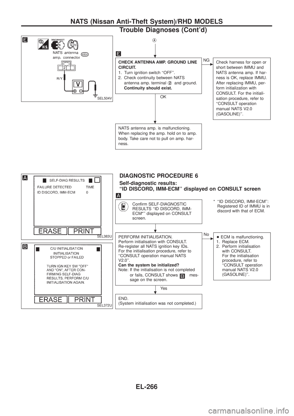
CHECK ANTENNA AMP. GROUND LINE
CIRCUIT.
1. Turn ignition switch ``OFF''.
2. Check continuity between NATS
antenna amp. terminalj
2and ground.
Continuity should exist.
OK
cNG
Check harness for open or
short between IMMU and
NATS antenna amp. If har-
ness is OK, replace IMMU.
After replacing IMMU, per-
form initialization with
CONSULT. For the initiali-
sation procedure, refer to
``CONSULT operation
manual NATS V2.0
(GASOLINE)''.
NATS antenna amp. is malfunctioning.
When replacing the amp. hold on to amp.
body. Take care not to pull on amp. har-
ness.
DIAGNOSTIC PROCEDURE 6
Self-diagnostic results:
``ID DISCORD, IMM-ECM'' displayed on CONSULT screen
Con®rm SELF-DIAGNOSTIC
RESULTS ``ID DISCORD, IMM-
ECM*'' displayed on CONSULT
screen.* ``ID DISCORD, IMM-ECM'':
Registered ID of IMMU is in
discord with that of ECM.
PERFORM INITIALISATION.
Perform initialisation with CONSULT.
Re-register all NATS ignition key IDs.
For the initialisation procedure, refer to
``CONSULT operation manual NATS
V2.0''.
Can the system be initialized?
Note: If the initialisation is not completed
or fails, CONSULT shows
mes-
sage on the screen.
Ye s
cNo
+ECM is malfunctioning.
1. Replace ECM.
2. Perform initialisation
with CONSULT.
For the initialisation
procedure, refer to
``CONSULT operation
manual NATS V2.0
(GASOLINE)''.
END.
(System initialisation was not completed.)
SEL504V
SEL383U
SEL372U
.
.
.
.
NATS (Nissan Anti-Theft System)/RHD MODELS
Trouble Diagnoses (Cont'd)
EL-266
Page 613 of 1226
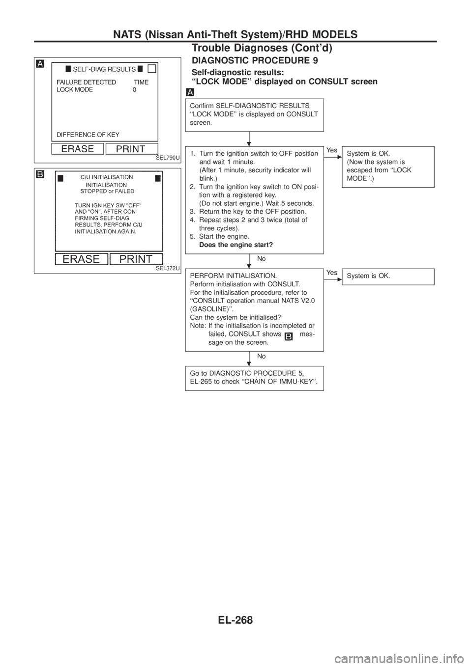
DIAGNOSTIC PROCEDURE 9
Self-diagnostic results:
``LOCK MODE'' displayed on CONSULT screen
Con®rm SELF-DIAGNOSTIC RESULTS
``LOCK MODE'' is displayed on CONSULT
screen.
1. Turn the ignition switch to OFF position
and wait 1 minute.
(After 1 minute, security indicator will
blink.)
2. Turn the ignition key switch to ON posi-
tion with a registered key.
(Do not start engine.) Wait 5 seconds.
3. Return the key to the OFF position.
4. Repeat steps 2 and 3 twice (total of
three cycles).
5. Start the engine.
Does the engine start?
No
cYe s
System is OK.
(Now the system is
escaped from ``LOCK
MODE''.)
PERFORM INITIALISATION.
Perform initialisation with CONSULT.
For the initialisation procedure, refer to
``CONSULT operation manual NATS V2.0
(GASOLINE)''.
Can the system be initialised?
Note: If the initialisation is incompleted or
failed, CONSULT shows
mes-
sage on the screen.
No
cYe s
System is OK.
Go to DIAGNOSTIC PROCEDURE 5,
EL-265 to check ``CHAIN OF IMMU-KEY''.
SEL790U
SEL372U
.
.
.
NATS (Nissan Anti-Theft System)/RHD MODELS
Trouble Diagnoses (Cont'd)
EL-268
Page 687 of 1226
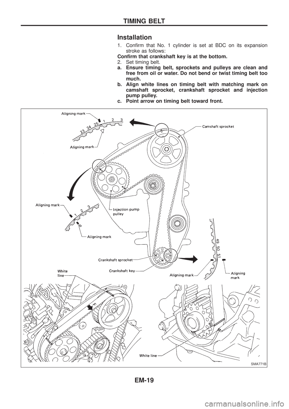
Installation
1. Con®rm that No. 1 cylinder is set at BDC on its expansion
stroke as follows:
Con®rm that crankshaft key is at the bottom.
2. Set timing belt.
a. Ensure timing belt, sprockets and pulleys are clean and
free from oil or water. Do not bend or twist timing belt too
much.
b. Align white lines on timing belt with matching mark on
camshaft sprocket, crankshaft sprocket and injection
pump pulley.
c. Point arrow on timing belt toward front.
SMA771B
TIMING BELT
EM-19
Page 775 of 1226

General Precautions
+Do not operate the engine for an extended period of time with-
out proper exhaust ventilation.
Keep the work area well ventilated and free of any in¯ammable
materials. Special care should be taken when handling any
in¯ammable or poisonous materials, such as gasoline, refriger-
ant gas, etc. When working in a pit or other enclosed area, be
sure to properly ventilate the area before working with hazard-
ous materials.
Do not smoke while working on the vehicle.
+Before jacking up the vehicle, apply wheel chocks or other tire
blocks to the wheels to prevent the vehicle from moving. After
jacking up the vehicle, support the vehicle weight with safety
stands at the points designated for proper lifting before work-
ing on the vehicle.
These operations should be done on a level surface.
+When removing a heavy component such as the engine or
transaxle/transmission, be careful not to lose your balance and
drop it. Also, do not allow it to strike adjacent parts, especially
the brake tubes and master cylinder.
+Before starting repairs which do not require battery power:
Turn off ignition switch.
Disconnect the negative battery terminal.
+To prevent serious burns:
Avoid contact with hot metal parts.
Do not remove the radiator cap when the engine is hot.
+Before servicing the vehicle:
Protect fenders, upholstery and carpeting with appropriate cov-
ers.
Take caution that keys, buckles or buttons do not scratch paint.
SGI285
SGI231
SEF289H
SGI233
SGI234
PRECAUTIONS
GI-2
Page 793 of 1226
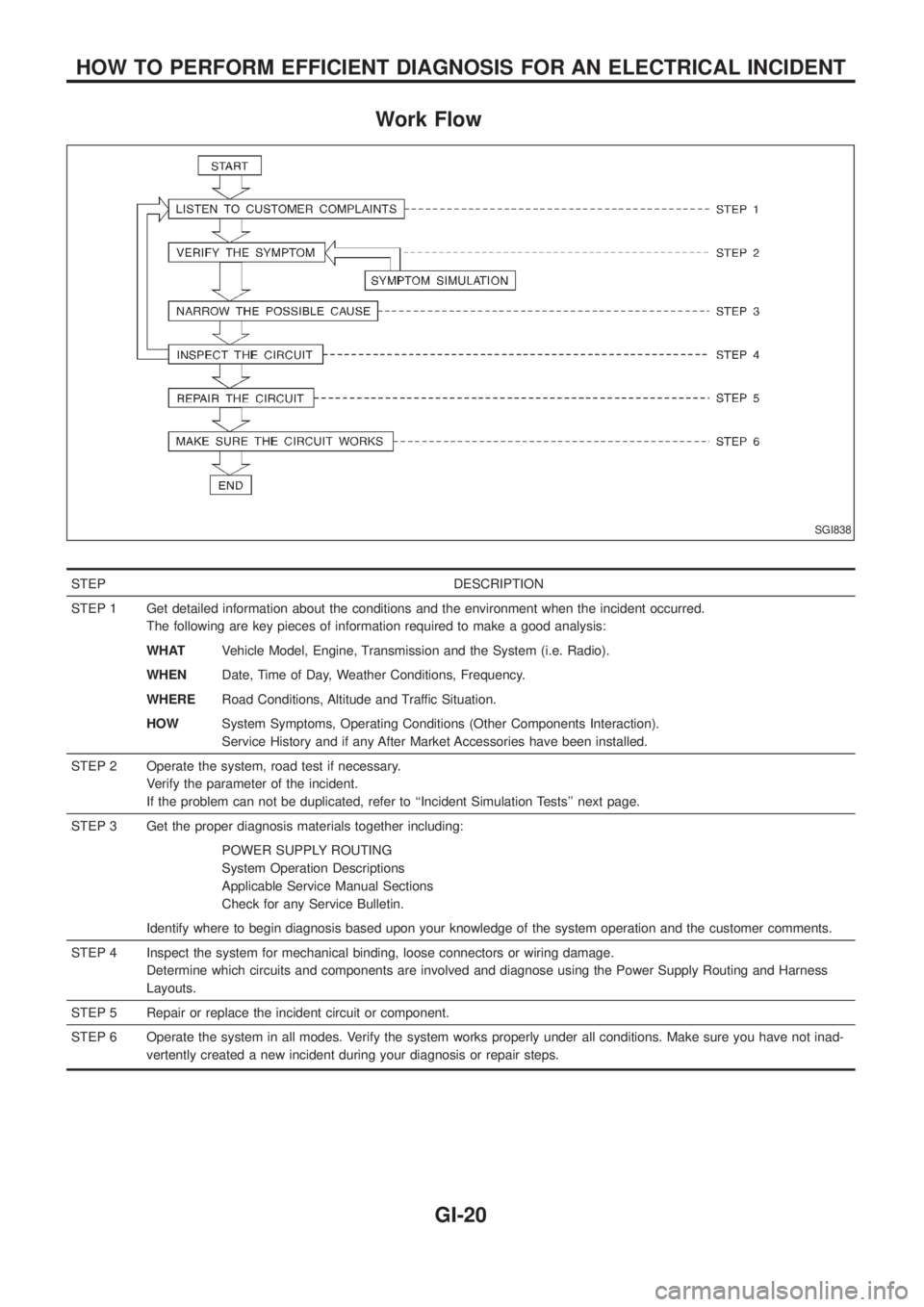
Work Flow
STEP DESCRIPTION
STEP 1 Get detailed information about the conditions and the environment when the incident occurred.
The following are key pieces of information required to make a good analysis:
WHATVehicle Model, Engine, Transmission and the System (i.e. Radio).
WHENDate, Time of Day, Weather Conditions, Frequency.
WHERERoad Conditions, Altitude and Traffic Situation.
HOWSystem Symptoms, Operating Conditions (Other Components Interaction).
Service History and if any After Market Accessories have been installed.
STEP 2 Operate the system, road test if necessary.
Verify the parameter of the incident.
If the problem can not be duplicated, refer to ``Incident Simulation Tests'' next page.
STEP 3 Get the proper diagnosis materials together including:
POWER SUPPLY ROUTING
System Operation Descriptions
Applicable Service Manual Sections
Check for any Service Bulletin.
Identify where to begin diagnosis based upon your knowledge of the system operation and the customer comments.
STEP 4 Inspect the system for mechanical binding, loose connectors or wiring damage.
Determine which circuits and components are involved and diagnose using the Power Supply Routing and Harness
Layouts.
STEP 5 Repair or replace the incident circuit or component.
STEP 6 Operate the system in all modes. Verify the system works properly under all conditions. Make sure you have not inad-
vertently created a new incident during your diagnosis or repair steps.
SGI838
HOW TO PERFORM EFFICIENT DIAGNOSIS FOR AN ELECTRICAL INCIDENT
GI-20
Page 799 of 1226
Voltage check method
1. Remove the blown fuse and disconnect all loads (i.e. SW1 open, relay disconnected and solenoid discon-
nected) powered through the fuse.
2. Turn the ignition key to the ON or START position. Verify battery voltage at the B
+side of the fuse ter-
minal (one lead on the B
+terminal side of the fuse block and one lead on a known good ground).
3. With SW1 open and the DMM leads across both fuse terminals, check for voltage.
voltage; short is between fuse block and SW1 (point A).
no voltage; short is further down the circuit than SW1.
4. With SW1 closed, relay and solenoid disconnected and the DMM leads across both fuse terminals, check
for voltage.
voltage; short is between SW1 and the relay (point B).
no voltage; short is further down the circuit than the relay.
5. With SW1 closed, relay contacts jumped with fused jumper wire check for voltage.
voltage; short is down the circuit of the relay or between the relay and the disconnected solenoid
(point C).
no voltage; retrace steps and check power to fuse block.
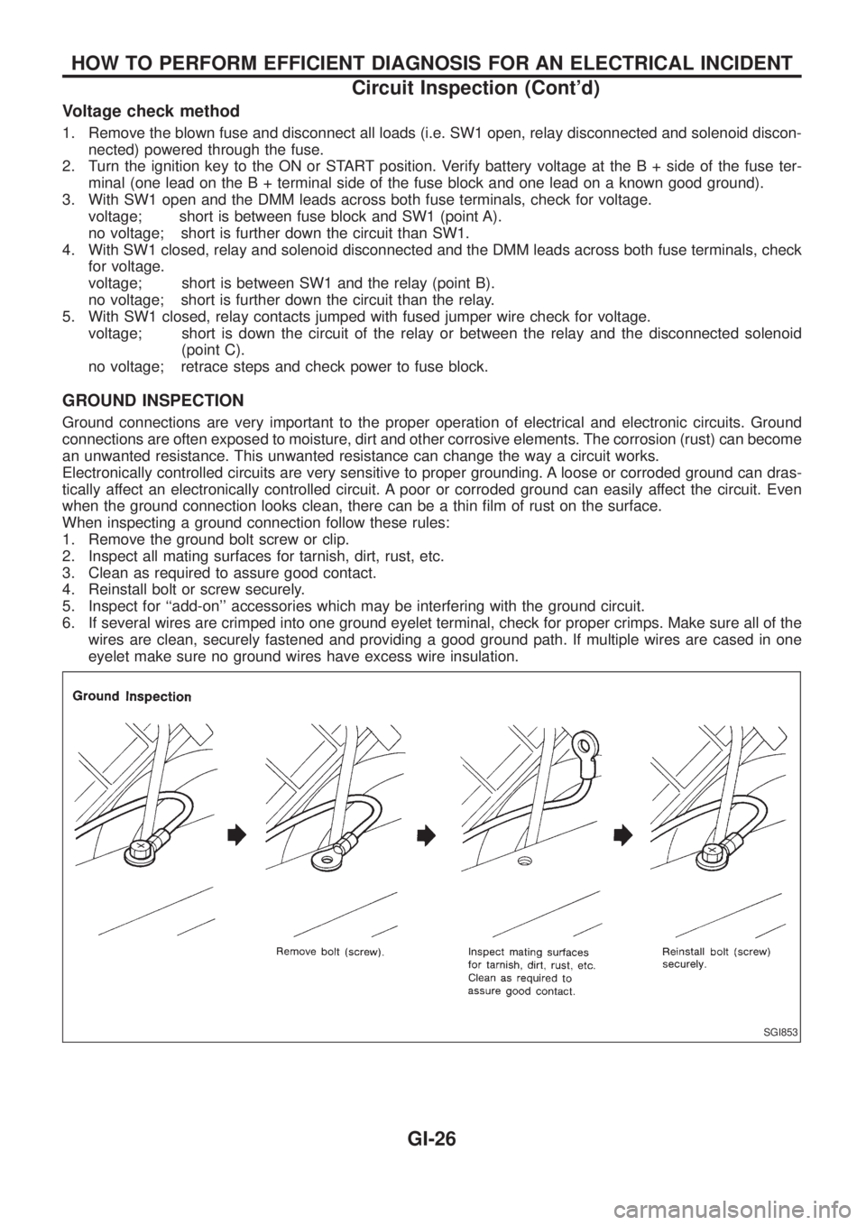
GROUND INSPECTION
Ground connections are very important to the proper operation of electrical and electronic circuits. Ground
connections are often exposed to moisture, dirt and other corrosive elements. The corrosion (rust) can become
an unwanted resistance. This unwanted resistance can change the way a circuit works.
Electronically controlled circuits are very sensitive to proper grounding. A loose or corroded ground can dras-
tically affect an electronically controlled circuit. A poor or corroded ground can easily affect the circuit. Even
when the ground connection looks clean, there can be a thin ®lm of rust on the surface.
When inspecting a ground connection follow these rules:
1. Remove the ground bolt screw or clip.
2. Inspect all mating surfaces for tarnish, dirt, rust, etc.
3. Clean as required to assure good contact.
4. Reinstall bolt or screw securely.
5. Inspect for ``add-on'' accessories which may be interfering with the ground circuit.
6. If several wires are crimped into one ground eyelet terminal, check for proper crimps. Make sure all of the
wires are clean, securely fastened and providing a good ground path. If multiple wires are cased in one
eyelet make sure no ground wires have excess wire insulation.
SGI853
HOW TO PERFORM EFFICIENT DIAGNOSIS FOR AN ELECTRICAL INCIDENT
Circuit Inspection (Cont'd)
GI-26
Page 805 of 1226
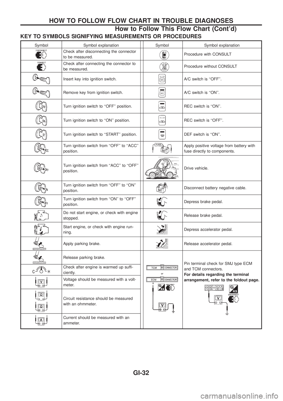
KEY TO SYMBOLS SIGNIFYING MEASUREMENTS OR PROCEDURES
Symbol Symbol explanation Symbol Symbol explanation
Check after disconnecting the connector
to be measured.Procedure with CONSULT
Check after connecting the connector to
be measured.Procedure without CONSULT
Insert key into ignition switch.A/C switch is ``OFF''.
Remove key from ignition switch.A/C switch is ``ON''.
Turn ignition switch to ``OFF'' position.REC switch is ``ON''.
Turn ignition switch to ``ON'' position.REC switch is ``OFF''.
Turn ignition switch to ``START'' position.DEF switch is ``ON''.
Turn ignition switch from ``OFF'' to ``ACC''
position.Apply positive voltage from battery with
fuse directly to components.
Turn ignition switch from ``ACC'' to ``OFF''
position.Drive vehicle.
Turn ignition switch from ``OFF'' to ``ON''
position.Disconnect battery negative cable.
Turn ignition switch from ``ON'' to ``OFF''
position.Depress brake pedal.
Do not start engine, or check with engine
stopped.Release brake pedal.
Start engine, or check with engine run-
ning.Depress accelerator pedal.
Apply parking brake.Release accelerator pedal.
Release parking brake.
Pin terminal check for SMJ type ECM
and TCM connectors.
For details regarding the terminal
arrangement, refer to the foldout page.Check after engine is warmed up suffi-
ciently.
Voltage should be measured with a volt-
meter.
Circuit resistance should be measured
with an ohmmeter.
Current should be measured with an
ammeter.
HOW TO FOLLOW FLOW CHART IN TROUBLE DIAGNOSES
How to Follow This Flow Chart (Cont'd)
GI-32