Page 464 of 1226
a) The temperature detected by the ambient air temperature sensor is lower than the indicated tem-
perature on the thermometer.
b) The difference in temperature detected during a period of 40 seconds is less than 1ÉC (1.8ÉF) when
vehicle speed has been greater than 24 km/h (15 MPH) for more than 100 seconds.
(This is to prevent the indicated temperature from being affected by engine heat or cooling fan
operation during low-speed driving.)
c) The ignition key has been turned to the ``OFF'' position for more than 4 hours. (The engine is cold.)
Calibration Procedure For Compass
The difference between magnetic North and geographical North
can sometimes be great enough to cause false compass readings.
In order for the compass to operate accurately in a particular zone,
it must be calibrated using the following procedure.
1. Determine your location on the worldwide magnetic variation
map on next page. Record your zone number.
2. Turn the ignition switch to ACC or ON position.
3. Push the ``Mode'' switch continuously for ®ve seconds until the
current zone entry number is displayed.
4. Press the ``Mode'' switch repeatedly until the desired zone num-
ber is displayed.
Once the desired zone number is displayed, stop pressing the
``Mode'' switch and the display will show compass direction after a
few seconds.
CORRECTION FUNCTIONS OF COMPASS
The direction display is equipped with automatic correction func-
tion. If the direction is not shown correctly, carry out initial correc-
tion.
INITIAL CORRECTION PROCEDURE FOR COMPASS
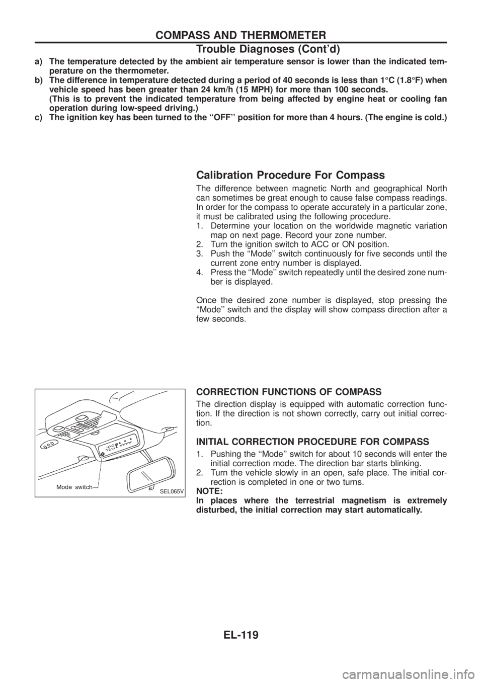
1. Pushing the ``Mode'' switch for about 10 seconds will enter the
initial correction mode. The direction bar starts blinking.
2. Turn the vehicle slowly in an open, safe place. The initial cor-
rection is completed in one or two turns.
NOTE:
In places where the terrestrial magnetism is extremely
disturbed, the initial correction may start automatically.
SEL065V
COMPASS AND THERMOMETER
Trouble Diagnoses (Cont'd)
EL-119
Page 480 of 1226
System Description
The warning chime is combined with the smart entrance control unit.
Both the ignition key and light warning chime will not sound, when ignition switch in the ON or START posi-
tion. (When power supply exists at smart entrance control unit terminalj
12.)
IGNITION KEY WARNING CHIME
With the key in the ignition key cylinder, the ignition switch in the OFF or ACC position, and the driver's door
open, the warning chime will sound. A battery positive voltage is supplied
+from key switch terminalj
1
+to smart entrance control unit terminalj1.
Ground is supplied
+through driver side door switch
+to smart entrance control unit terminalj
7.
LIGHT WARNING CHIME
With ignition switch in the OFF or ACC position, driver's door open, and lighting switch in 1ST or 2ND position,
warning chime will sound. A battery positive voltage is supplied
+from lighting switch terminalj
12or daytime light control unit
+to smart entrance control unit terminalj
14.
Ground is supplied
+through driver side door switch
+to smart entrance control unit terminalj
7.
WARNING CHIME
EL-135
Page 483 of 1226
Trouble Diagnoses
SYMPTOM CHART
REFERENCE PAGE EL-138 EL-139 EL-139
SYMPTOM
DIAGNOSTIC PROCEDURE 1
(Lighting switch input signal check)
DIAGNOSTIC PROCEDURE 2
(Key switch input signal check)
DIAGNOSTIC PROCEDURE 3
Light warning chime does not acti-
vate.XX
Ignition key warning chime does not
activate.XX
All warning chimes do not activate.X
DIAGNOSTIC PROCEDURE 1
(Lighting switch input signal check)
CHECK LIGHTING SWITCH INPUT SIG-
NAL.
Check voltage between control unit termi-
nalj
14and ground.
OK
cNG
Check the following.
+7.5A fuse (No.
42,
located in the fuse and
fusible link box) for LHD
models
+Harness for open or
short between control
unit and lighting switch/
daytime light control unit
Go to DIAGNOSTIC PROCEDURE 3.
Condition of lighting
switchVoltage [V]
1ST or 2ND Approx. 12
OFF 0
SEL851UB
.
WARNING CHIME
EL-138
Page 484 of 1226
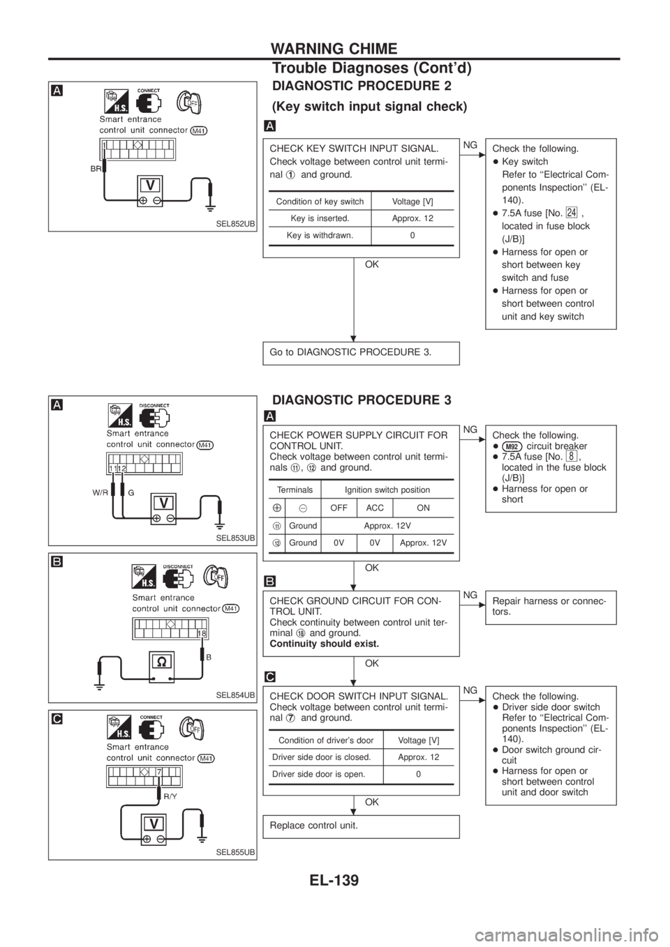
DIAGNOSTIC PROCEDURE 2
(Key switch input signal check)
CHECK KEY SWITCH INPUT SIGNAL.
Check voltage between control unit termi-
nalj
1and ground.
OK
cNG
Check the following.
+Key switch
Refer to ``Electrical Com-
ponents Inspection'' (EL-
140).
+7.5A fuse [No.
24,
located in fuse block
(J/B)]
+Harness for open or
short between key
switch and fuse
+Harness for open or
short between control
unit and key switch
Go to DIAGNOSTIC PROCEDURE 3.
Condition of key switch Voltage [V]
Key is inserted. Approx. 12
Key is withdrawn. 0
DIAGNOSTIC PROCEDURE 3
CHECK POWER SUPPLY CIRCUIT FOR
CONTROL UNIT.
Check voltage between control unit termi-
nalsj
11,j12and ground.
OK
cNG
Check the following.
+
M92circuit breaker
+7.5A fuse [No.8,
located in the fuse block
(J/B)]
+Harness for open or
short
CHECK GROUND CIRCUIT FOR CON-
TROL UNIT.
Check continuity between control unit ter-
minalj
18and ground.
Continuity should exist.
OK
cNG
Repair harness or connec-
tors.
CHECK DOOR SWITCH INPUT SIGNAL.
Check voltage between control unit termi-
nalj
7and ground.
OK
cNG
Check the following.
+Driver side door switch
Refer to ``Electrical Com-
ponents Inspection'' (EL-
140).
+Door switch ground cir-
cuit
+Harness for open or
short between control
unit and door switch
Replace control unit.
Terminals Ignition switch position
Å@OFF ACC ON
j
11Ground Approx. 12V
j
12Ground 0V 0V Approx. 12V
Condition of driver's door Voltage [V]
Driver side door is closed. Approx. 12
Driver side door is open. 0
SEL852UB
SEL853UB
SEL854UB
SEL855UB
.
.
.
.
WARNING CHIME
Trouble Diagnoses (Cont'd)
EL-139
Page 485 of 1226
Electrical Components Inspection
KEY SWITCH (insert)
Check continuity between terminals when key is inserted in ignition
key cylinder and key is removed from ignition key cylinder.
Terminal No. Condition Continuity
j
1-j2Key is inserted. Yes
Key is removed. No
DRIVER SIDE DOOR SWITCH
Check continuity between terminals when door switch is pushed
and released.
Terminal No. Condition Continuity
j
1-j3Door switch is pushed. No
Door switch is released. Yes
SEL462V
SEL463V
WARNING CHIME
EL-140
Page 549 of 1226
System Description
Power is supplied at all times
+through 40A fusible link (Letter
e, located in the fuse and fusible link box)
+to circuit breaker terminalj
1
+through circuit breaker terminalj2
+to smart entrance control unit terminalj11.
Ground is supplied to smart entrance control unit terminalj
18through body grounds.
INPUT
When the door lock & unlock switch (power window main switch) is in LOCKED position, ground signal is
supplied
+to smart entrance control unit terminalj
4
+through door lock & unlock switch terminalj14.
When the door lock & unlock switch (power window main switch) is in UNLOCKED position, ground signal is
supplied
+to smart entrance control unit terminalj
5
+through door lock & unlock switch terminalj7.
Driver side door key cylinder and driver side lock knob are connected to driver side door lock switch with a
rod. When driver side door lock switch is in UNLOCKED position, ground signal is supplied
+to smart entrance control unit terminalj
2
+through driver side door lock switch terminalj1(without multi-remote control system) or
+through driver side door lock actuator terminalj
2(with multi-remote control system).
When driver side door lock switch is in LOCKED position, ground signal is interrupted.
Door lock operates according to the conditions of the door lock & unlock switch (power window main switch)
and driver side door lock switch.
OUTPUT
Unlock
Ground is supplied
+to passenger side door lock actuator, rear door lock actuator LH and RH terminalj
3
+through smart entrance control unit terminalj15.
Power is supplied
+to passenger side door lock actuator, rear door lock actuator LH and RH terminalj
1
+through smart entrance control unit terminalj16.
Then, the doors are unlocked.
Lock
Ground is supplied
+to passenger side door lock actuator, rear door lock actuator LH and RH terminalj
1
+through smart entrance control unit terminalj16.
Power is supplied
+to passenger side door lock actuator, rear door lock actuator LH and RH terminalj
3
+through smart entrance control unit terminalj15.
Then, the doors are locked.
POWER DOOR LOCK
EL-204
Page 552 of 1226
Trouble Diagnosis
SYMPTOM CHART
REFERENCE PAGE EL-207 EL-208 EL-209 EL-210
SYMPTOM
MAIN POWER SUPPLY AND GROUND CIRCUIT CHECK
DIAGNOSTIC PROCEDURE 1
(Door lock/unlock switch check)
DIAGNOSTIC PROCEDURE 2
(Door lock actuator check)
DIAGNOSTIC PROCEDURE 3
(Driver side door lock switch check)
None of the doors lock/unlock when operat-
ing any switch.XX
One or more doors are not locked and/or
unlocked.X
Door lock/unlock switch does not operate. X
Door knob lock switch/key cylinder on driv-
er's door does not operate.X
Driver side door does not lock/unlock when
operating remote controller. (With multi-re-
mote control system)X
POWER SUPPLY AND GROUND CIRCUIT CHECK
Power supply circuit check
Terminal Ignition switch
Å@OFF ACC ON
j
11GroundBattery
voltageBattery
voltageBattery
voltage
Ground circuit check
Terminals Continuity
j
18- Ground Yes
SEL860UB
SEL854UD
POWER DOOR LOCK
EL-207
Page 557 of 1226
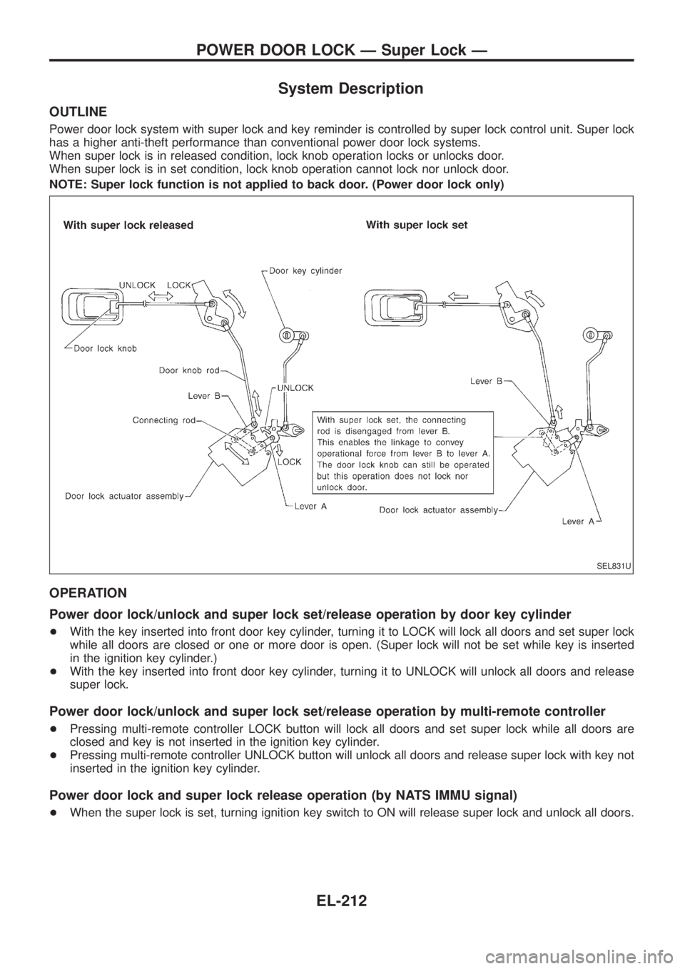
System Description
OUTLINE
Power door lock system with super lock and key reminder is controlled by super lock control unit. Super lock
has a higher anti-theft performance than conventional power door lock systems.
When super lock is in released condition, lock knob operation locks or unlocks door.
When super lock is in set condition, lock knob operation cannot lock nor unlock door.
NOTE: Super lock function is not applied to back door. (Power door lock only)
OPERATION
Power door lock/unlock and super lock set/release operation by door key cylinder
+With the key inserted into front door key cylinder, turning it to LOCK will lock all doors and set super lock
while all doors are closed or one or more door is open. (Super lock will not be set while key is inserted
in the ignition key cylinder.)
+With the key inserted into front door key cylinder, turning it to UNLOCK will unlock all doors and release
super lock.
Power door lock/unlock and super lock set/release operation by multi-remote controller
+Pressing multi-remote controller LOCK button will lock all doors and set super lock while all doors are
closed and key is not inserted in the ignition key cylinder.
+Pressing multi-remote controller UNLOCK button will unlock all doors and release super lock with key not
inserted in the ignition key cylinder.
Power door lock and super lock release operation (by NATS IMMU signal)
+When the super lock is set, turning ignition key switch to ON will release super lock and unlock all doors.
SEL831U
POWER DOOR LOCK Ð Super Lock Ð
EL-212