2006 NISSAN PATROL engine oil check
[x] Cancel search: engine oil checkPage 985 of 1226
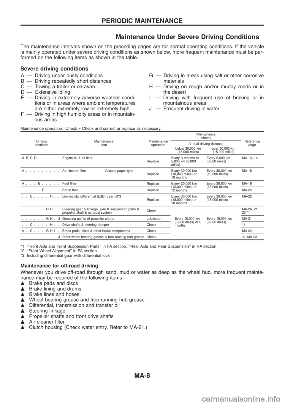
Maintenance Under Severe Driving Conditions
The maintenance intervals shown on the preceding pages are for normal operating conditions. If the vehicle
is mainly operated under severe driving conditions as shown below, more frequent maintenance must be per-
formed on the following items as shown in the table.
Severe driving conditions
A Ð Driving under dusty conditions
B Ð Driving repeatedly short distances
C Ð Towing a trailer or caravan
D Ð Extensive idling
E Ð Driving in extremely adverse weather condi-
tions or in areas where ambient temperatures
are either extremely low or extremely high
F Ð Driving in high humidity areas or in mountain-
ous areasG Ð Driving in areas using salt or other corrosive
materials
H Ð Driving on rough and/or muddy roads or in
the desert
I Ð Driving with frequent use of braking or in
mountainous areas
J Ð Frequent driving in water
Maintenance operation: Check = Check and correct or replace as necessary.
Driving
conditionMaintenance
itemMaintenance
operationMaintenance
interval
Reference
page Annual driving distance
below 30,000 km
(18,000 miles)over 30,000 km
(18,000 miles)
ABCD......Engine oil & oil ®lter
ReplaceEvery 3 months or
5,000 km (3,000
miles)Every 5,000 km
(3,000 miles)MA-13, 14
A.........Aircleaner ®lter Viscous paper type
ReplaceEvery 30,000 km
(18,000 miles) or
18 monthsEvery 30,000 km
(18,000 miles)MA-18
A...E.....Fuel ®lter
ReplaceEvery 20,000 km
(12,000 miles) or
12 monthsEvery 30,000 km
(18,000 miles)MA-16
.....F....Brake ¯uid
ReplaceMA-24
..C....H..Limited slip differential (LSD) gear oil*3
ReplaceEvery 30,000 km
(18,000 miles) or
18 monthsEvery 30,000 km
(18,000 miles)MA-22
......GH..Steering gear & linkage, axle & suspension parts &
propeller shaft & exhaust systemCheck
Every 10,000 km
(6,000 miles) or 6
monthsEvery 15,000 km
(9,000 miles)MA-26, 21,
23 *1
......GH.JGreasing points of propeller shafts Lubricate MA-21
..C....H..Drive shafts & steering damper Check *1
A.C...GHI.Brake pads, discs & other brake components Check MA-24
.........JFront wheel bearing grease & free-running hub grease Check *2, MA-23
*1: ``Front Axle and Front Suspension Parts'' in FA section, ``Rear Axle and Rear Suspension'' in RA section
*2: ``Front Wheel Alignment'' in FA section
*3: Including differential gear with differential lock
Maintenance for off-road driving
Whenever you drive off-road through sand, mud or water as deep as the wheel hub, more frequent mainte-
nance may be required of the following items:
mBrake pads and discs
mBrake lining and drums
mBrake lines and hoses
mWheel bearing grease and free-running hub grease
mDifferential, transmission and transfer oil
mSteering linkage
mPropeller shafts and front drive shafts
mAir cleaner ®lter
mClutch housing (Check water entry. Refer to MA-21.)
PERIODIC MAINTENANCE
MA-8
Page 990 of 1226

1. Inspect for cracks, fraying, wear or oil adhesion. Replace if
necessary.
The belts should not touch the bottom of the pulley groove.
2. Check drive belt de¯ection by pushing on the belt midway
between pulleys.
Adjust if belt de¯ections exceed the limit.
Unit: mm (in)
Used belt de¯ection
De¯ection of new belt
LimitDe¯ection after
adjustment
Alternator 17 (0.67) 12 - 14 (0.47 - 0.55) 9 - 11 (0.35 - 0.43)
Air conditioner
compressor11 (0.43)7 - 9 (0.28 - 0.35)6 - 8 (0.24 - 0.31)
Power steering oil
pump14 (0.55) 10 - 12 (0.39 - 0.47) 9 - 11 (0.35 - 0.43)
Applied pushing
force98 N (10 kg, 22 lb)
Check drive belt de¯ections when engine is cold.
Changing Engine Oil
WARNING:
+Be careful not to burn yourself, as engine oil is hot.
+Prolonged and repeated contact with used engine oil may
cause skin cancer; try to avoid direct skin contact with
used oil. If skin contact is made, wash thoroughly with
soap or hand cleaner as soon as possible.
1. Warm up engine, and check for oil leakage from engine com-
ponents.
2. Remove oil ®ller cap and drain plug.
3. Drain oil and ®ll with new engine oil.
Oil grade: CCMC PD1 or PD2
Viscosity:
See ``RECOMMENDED FLUIDS AND
LUBRICANTS'', MA-9.
Re®ll oil capacity (approximate):
Without oil ®lter change
6.4!(5-5/8 Imp qt)
With oil ®lter change
5.8!(5-1/8 Imp qt)
CAUTION:
+Be sure to clean and install oil pan drain plug with washer.
Drain plug:
:29-39Nzm (3.0 - 4.0 kg-m, 22 - 29 ft-lb)
+The re®ll capacity changes depending on the oil tempera-
ture and drain time; use these valves as a reference and be
certain to check with the dipstick when changing the oil.
SMA998C
ENGINE MAINTENANCE
Checking Drive Belt (Cont'd)
MA-13
Page 991 of 1226
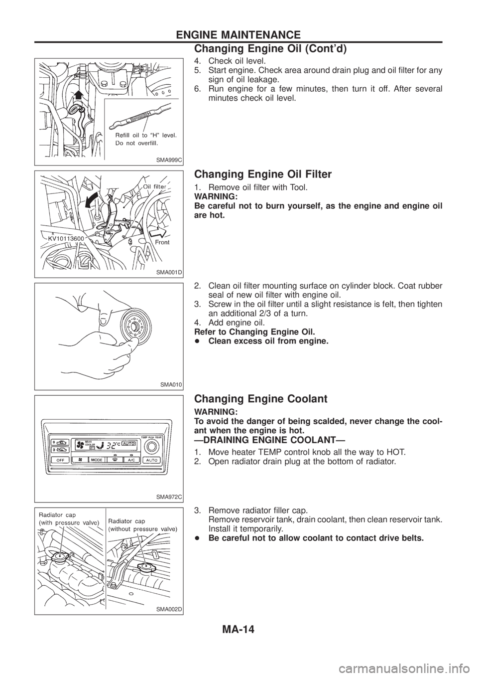
4. Check oil level.
5. Start engine. Check area around drain plug and oil ®lter for any
sign of oil leakage.
6. Run engine for a few minutes, then turn it off. After several
minutes check oil level.
Changing Engine Oil Filter
1. Remove oil ®lter with Tool.
WARNING:
Be careful not to burn yourself, as the engine and engine oil
are hot.
2. Clean oil ®lter mounting surface on cylinder block. Coat rubber
seal of new oil ®lter with engine oil.
3. Screw in the oil ®lter until a slight resistance is felt, then tighten
an additional 2/3 of a turn.
4. Add engine oil.
Refer to Changing Engine Oil.
+Clean excess oil from engine.
Changing Engine Coolant
WARNING:
To avoid the danger of being scalded, never change the cool-
ant when the engine is hot.
ÐDRAINING ENGINE COOLANTÐ
1. Move heater TEMP control knob all the way to HOT.
2. Open radiator drain plug at the bottom of radiator.
3. Remove radiator ®ller cap.
Remove reservoir tank, drain coolant, then clean reservoir tank.
Install it temporarily.
+Be careful not to allow coolant to contact drive belts.
SMA999C
SMA001D
SMA010
SMA972C
SMA002D
ENGINE MAINTENANCE
Changing Engine Oil (Cont'd)
MA-14
Page 997 of 1226
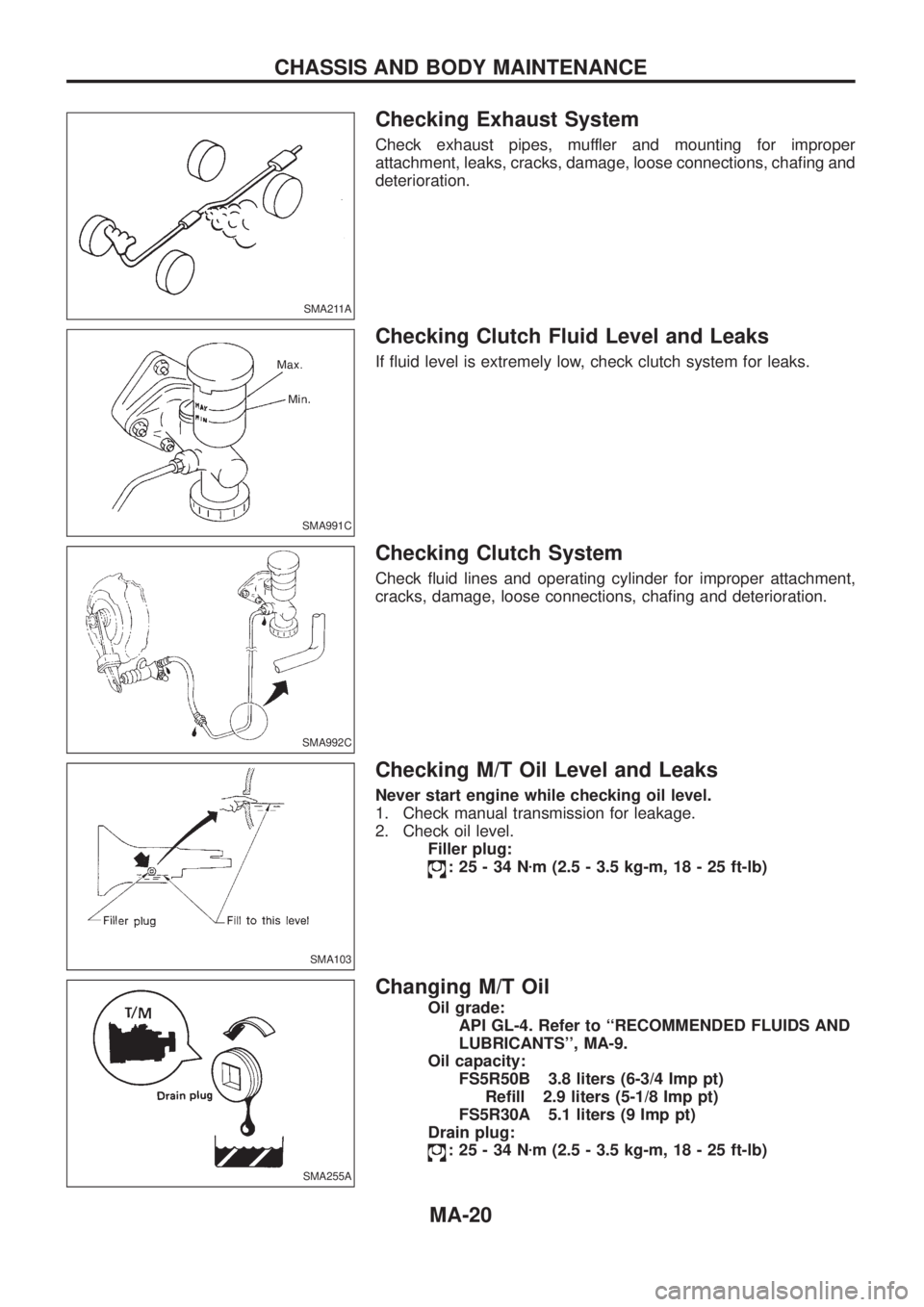
Checking Exhaust System
Check exhaust pipes, muffler and mounting for improper
attachment, leaks, cracks, damage, loose connections, cha®ng and
deterioration.
Checking Clutch Fluid Level and Leaks
If ¯uid level is extremely low, check clutch system for leaks.
Checking Clutch System
Check ¯uid lines and operating cylinder for improper attachment,
cracks, damage, loose connections, cha®ng and deterioration.
Checking M/T Oil Level and Leaks
Never start engine while checking oil level.
1. Check manual transmission for leakage.
2. Check oil level.
Filler plug:
:25-34Nzm (2.5 - 3.5 kg-m, 18 - 25 ft-lb)
Changing M/T Oil
Oil grade:
API GL-4. Refer to ``RECOMMENDED FLUIDS AND
LUBRICANTS'', MA-9.
Oil capacity:
FS5R50B 3.8 liters (6-3/4 Imp pt)
Re®ll 2.9 liters (5-1/8 Imp pt)
FS5R30A 5.1 liters (9 Imp pt)
Drain plug:
:25-34Nzm (2.5 - 3.5 kg-m, 18 - 25 ft-lb)
SMA211A
SMA991C
SMA992C
SMA103
SMA255A
CHASSIS AND BODY MAINTENANCE
MA-20
Page 1003 of 1226
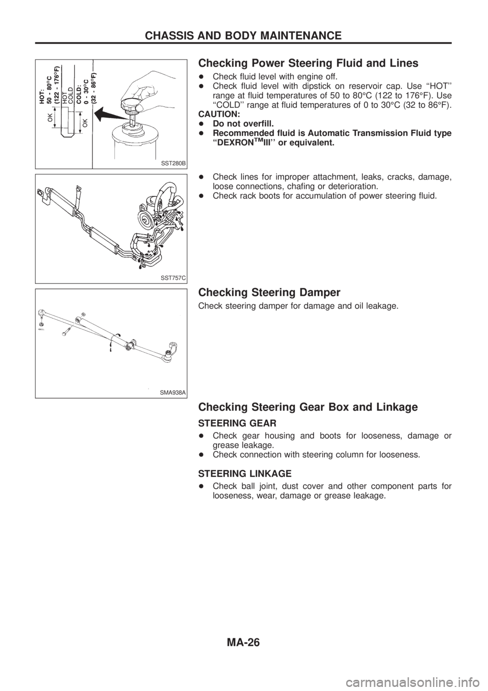
Checking Power Steering Fluid and Lines
+Check ¯uid level with engine off.
+Check ¯uid level with dipstick on reservoir cap. Use ``HOT''
range at ¯uid temperatures of 50 to 80ÉC (122 to 176ÉF). Use
``COLD'' range at ¯uid temperatures of 0 to 30ÉC (32 to 86ÉF).
CAUTION:
+Do not over®ll.
+Recommended ¯uid is Automatic Transmission Fluid type
``DEXRON
TMIII'' or equivalent.
+Check lines for improper attachment, leaks, cracks, damage,
loose connections, cha®ng or deterioration.
+Check rack boots for accumulation of power steering ¯uid.
Checking Steering Damper
Check steering damper for damage and oil leakage.
Checking Steering Gear Box and Linkage
STEERING GEAR
+Check gear housing and boots for looseness, damage or
grease leakage.
+Check connection with steering column for looseness.
STEERING LINKAGE
+Check ball joint, dust cover and other component parts for
looseness, wear, damage or grease leakage.
SST280B
SST757C
SMA938A
CHASSIS AND BODY MAINTENANCE
MA-26
Page 1097 of 1226
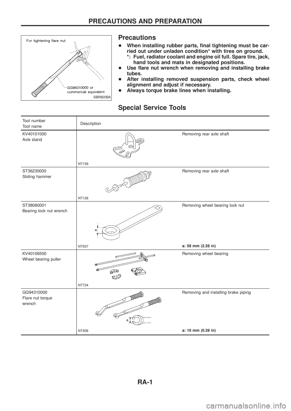
Precautions
+When installing rubber parts, ®nal tightening must be car-
ried out under unladen condition* with tires on ground.
*: Fuel, radiator coolant and engine oil full. Spare tire, jack,
hand tools and mats in designated positions.
+Use ¯are nut wrench when removing and installing brake
tubes.
+After installing removed suspension parts, check wheel
alignment and adjust if necessary.
+Always torque brake lines when installing.
Special Service Tools
Tool number
Tool nameDescription
KV40101000
Axle stand
NT159
Removing rear axle shaft
ST36230000
Sliding hammer
NT126
Removing rear axle shaft
ST38080001
Bearing lock nut wrench
NT507
Removing wheel bearing lock nut
a: 58 mm (2.28 in)
KV40106500
Wheel bearing puller
NT724
Removing wheel bearing
GG94310000
Flare nut torque
wrench
NT406
Removing and installing brake piping
a: 10 mm (0.39 in)
SBR820BA
PRECAUTIONS AND PREPARATION
RA-1
Page 1174 of 1226
Checking and Adjusting Drive Belts
Refer to MA section (``Checking Drive Belts'', ``ENGINE MAINTE-
NANCE'').
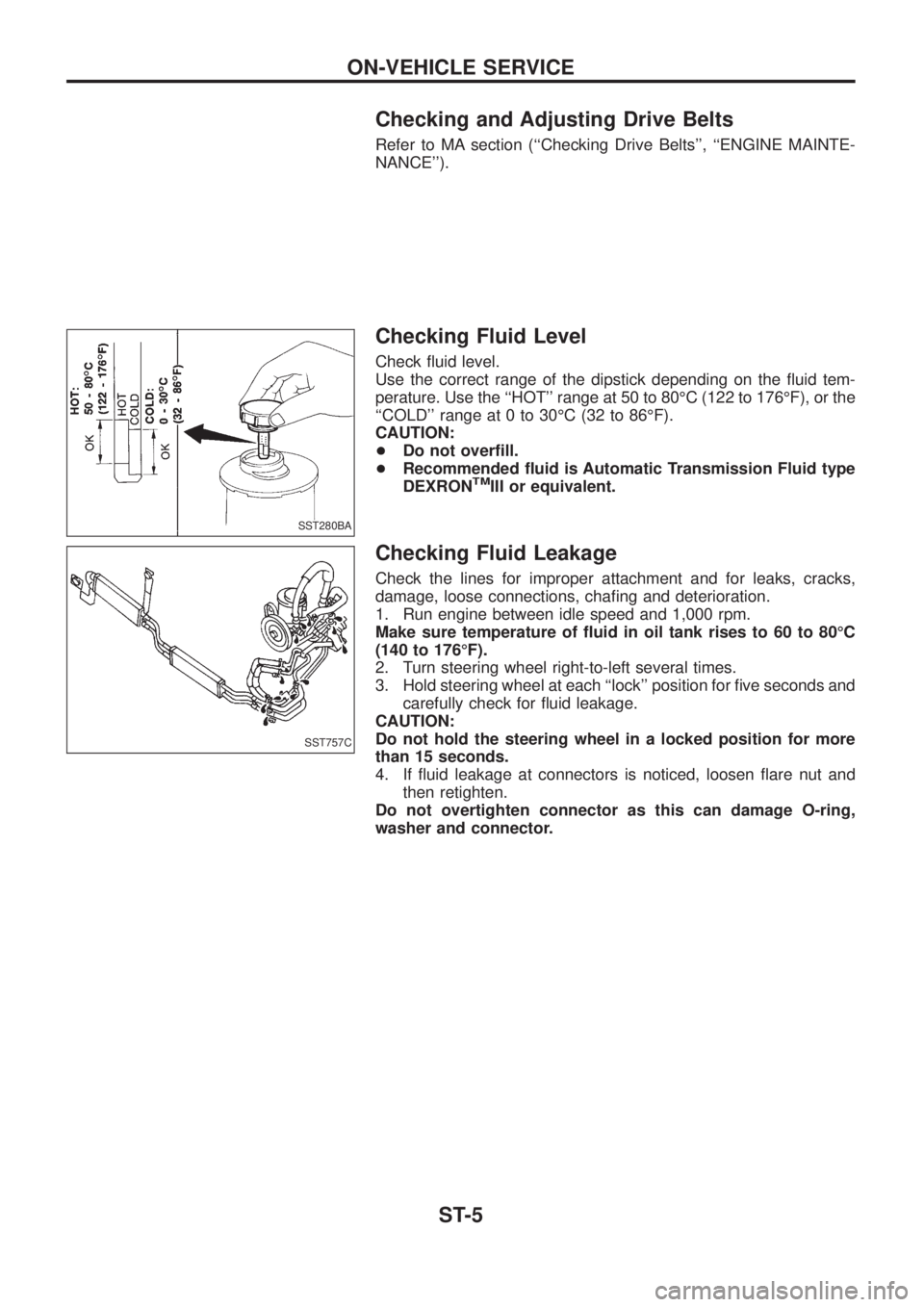
Checking Fluid Level
Check ¯uid level.
Use the correct range of the dipstick depending on the ¯uid tem-
perature. Use the ``HOT'' range at 50 to 80ÉC (122 to 176ÉF), or the
``COLD'' range at 0 to 30ÉC (32 to 86ÉF).
CAUTION:
+Do not over®ll.
+Recommended ¯uid is Automatic Transmission Fluid type
DEXRON
TMIII or equivalent.
Checking Fluid Leakage
Check the lines for improper attachment and for leaks, cracks,
damage, loose connections, cha®ng and deterioration.
1. Run engine between idle speed and 1,000 rpm.
Make sure temperature of ¯uid in oil tank rises to 60 to 80ÉC
(140 to 176ÉF).
2. Turn steering wheel right-to-left several times.
3. Hold steering wheel at each ``lock'' position for ®ve seconds and
carefully check for ¯uid leakage.
CAUTION:
Do not hold the steering wheel in a locked position for more
than 15 seconds.
4. If ¯uid leakage at connectors is noticed, loosen ¯are nut and
then retighten.
Do not overtighten connector as this can damage O-ring,
washer and connector.
SST280BA
SST757C
ON-VEHICLE SERVICE
ST-5
Page 1175 of 1226
Bleeding Hydraulic System
1. Raise front end of vehicle until wheels are clear of the ground.
2. Add ¯uid into oil tank to speci®ed level. Then, quickly turn steer-
ing wheel fully to right and left and lightly touch steering stop-
pers.
Repeat steering wheel operation until ¯uid level no longer
decreases.
3. Start engine.
Repeat step 2 above.
+Incomplete air bleeding will cause the following to occur. When
this happens, bleed air again.
a. Air bubbles in reservoir tank
b. Clicking noise in oil pump
c. Excessive buzzing in oil pump
Fluid noise may occur in the valve or oil pump. This is common
when the vehicle is stationary or while turning steering wheel
slowly. This does not affect performance or durability of the system.
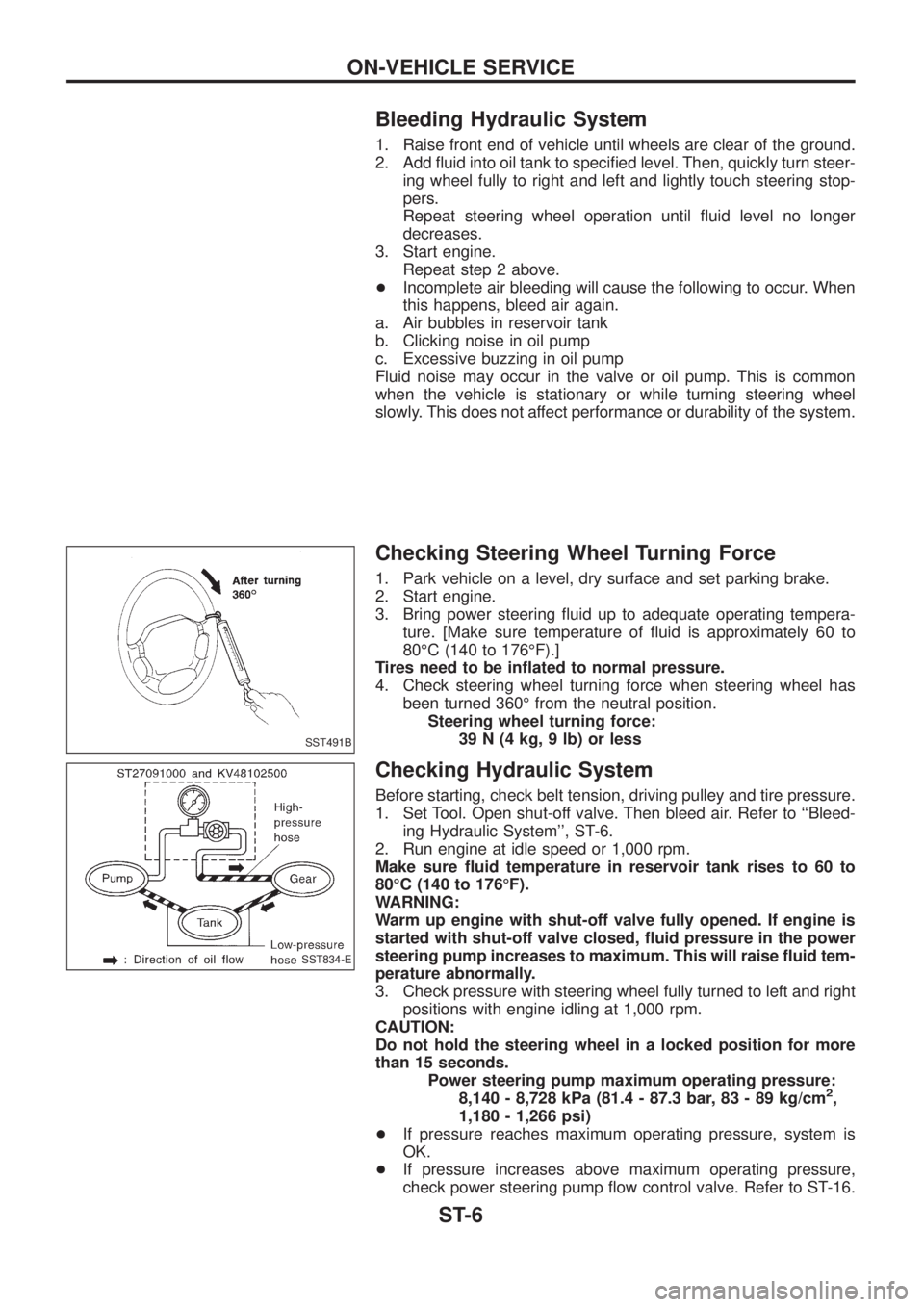
Checking Steering Wheel Turning Force
1. Park vehicle on a level, dry surface and set parking brake.
2. Start engine.
3. Bring power steering ¯uid up to adequate operating tempera-
ture. [Make sure temperature of ¯uid is approximately 60 to
80ÉC (140 to 176ÉF).]
Tires need to be in¯ated to normal pressure.
4. Check steering wheel turning force when steering wheel has
been turned 360É from the neutral position.
Steering wheel turning force:
39 N (4 kg, 9 lb) or less
Checking Hydraulic System
Before starting, check belt tension, driving pulley and tire pressure.
1. Set Tool. Open shut-off valve. Then bleed air. Refer to ``Bleed-
ing Hydraulic System'', ST-6.
2. Run engine at idle speed or 1,000 rpm.
Make sure ¯uid temperature in reservoir tank rises to 60 to
80ÉC (140 to 176ÉF).
WARNING:
Warm up engine with shut-off valve fully opened. If engine is
started with shut-off valve closed, ¯uid pressure in the power
steering pump increases to maximum. This will raise ¯uid tem-
perature abnormally.
3. Check pressure with steering wheel fully turned to left and right
positions with engine idling at 1,000 rpm.
CAUTION:
Do not hold the steering wheel in a locked position for more
than 15 seconds.
Power steering pump maximum operating pressure:
8,140 - 8,728 kPa (81.4 - 87.3 bar, 83 - 89 kg/cm
2,
1,180 - 1,266 psi)
+If pressure reaches maximum operating pressure, system is
OK.
+If pressure increases above maximum operating pressure,
check power steering pump ¯ow control valve. Refer to ST-16.
SST491B
SST834-E
ON-VEHICLE SERVICE
ST-6