2006 NISSAN PATROL cooling
[x] Cancel search: coolingPage 950 of 1226

Combination meter........................................EL-102
Combination switch .........................................EL-57
Combustion chamber replacement ................EM-32
Compass .......................................................EL-116
Compression pressure ...................................EM-10
Compressor special service tool ......................HA-6
Connecting rod...............................................EM-47
Connecting rod...............................................EM-51
Connector inspection .......................................GI-17
Console box - See Instrument panel ..............BT-11
Control lever (Transfer) .....................................TF-9
Control sleeve position sensor .......................EC-86
Coolant mixture ratio ......................................MA-11
Coolant replacement ......................................MA-14
Cooling circuit (engine) .....................................LC-9
Cooling fan control .......................................EC-112
Cooling fan motor .........................................EC-120
Cooling fan relay ..........................................EC-120
Cooling fan......................................................LC-15
Counter gear (M/T).........................................MT-10
Counter gear (Transfer) ..................................TF-11
Coupling sleeve (M/T) ....................................MT-10
Crankcase emission control system -
See Positive crankcase ventilation.............EC-21
Crankcase ventilation system - See
Positive crankcase ventilation ....................EC-21
Crankshaft position sensor (TDC)................EC-143
Crankshaft ......................................................EM-50
Cylinder block ..........................................EM-45, 48
Cylinder head .................................................EM-28
D
D/LOCK - Wiring diagram .............................EL-205
DEF - Wiring diagram ...................................EL-159
DEICER - Wiring diagram.............................EL-167
DTRL - Wiring diagram ...................................EL-67
Data link connector for Consult......................EC-36
Daytime light system.......................................EL-65
Diagnosis sensor unit .....................................RS-12
Diagnostic trouble code (DTC) for
ECCS OBD system ....................................EC-30
Differential carrier assembly...........................PD-31
Differential carrier disassembly ......................PD-14
Differential gear oil replacement ....................MA-22
Dimensions ......................................................GI-38
Dome light - See Interior lamp .......................EL-93
Door glass .........................................................BT-9
Door lock ...........................................................BT-9
Door mirror ......................................................BT-46
Door trim .........................................................BT-18
Door, front .........................................................BT-9
Door, rear ........................................................BT-10
Drive belt inspection ......................................MA-12
Drive chain (Transfer) .....................................TF-11
Drive pinion diff. inspection ............................PD-19
Drive pinion height .........................................PD-27
Drive shaft (front) ............................................FA-23
Dual pressure switch ......................................HA-11Dual pressure switch ......................................HA-97
E
ECCS basic inspection...................................EC-46
ECCS circuit diagram .....................................EC-11
ECCS component parts location ......................EC-8
ECCS on board diagnostic system ................EC-30
ECCS symptom matrix chart..........................EC-48
ECCS system diagram and chart ..................EC-12
ECCS-D control module .........................EC-54, 110
ECM input/output signal .................................EC-54
ECTS - Wiring diagram ..................................EC-78
EGR control (EGRC) - solenoid valve .........EC-155
EGR control valve ........................................EC-161
EGRC/V - Wiring diagram ............................EC-155
Electric governor ....................................EC-95, 148
Electric sunroof .............................................EL-186
Electrical diagnoses.........................................GI-20
Electrical unit.................................................EL-321
Electrical units location .................................EL-269
Electronic fuel injection pump ........................EC-27
Engine compartment .......................................BT-49
Engine coolant temperature sensor
(ECTS) ........................................................EC-78
Engine oil ®lter replacement ..........................MA-14
Engine oil precautions .......................................GI-4
Engine oil replacement ..................................MA-13
Engine outer component parts ........................EM-8
Engine removal ..............................................EM-43
Engine room - See Engine
compartment ...............................................BT-49
Engine serial number ......................................GI-37
Exhaust system inspection ............................MA-20
Exhaust system ................................................FE-3
Exterior ............................................................BT-26
F
FCUT - Wiring diagram ................................EC-129
FTS - Wiring diagram ...................................EC-134
Fan control amp. ............................................HA-88
Final drive disassembly ..................................PD-14
Final drive removal and installation................PD-11
Finisher, interior - See Trim ............................BT-14
Floor trim .........................................................BT-14
Flow charts ......................................................GI-30
Fluids................................................................MA-9
Flywheel (clutch).......................................CL-13, 14
Flywheel runout..............................................EM-52
Fog lamp, rear ................................................EL-80
Fork rod (M/T) ................................................MT-12
Front axle ........................................................FA-10
Front bumper ....................................................BT-4
Front case (Transfer) ......................................TF-10
Front disc brake .............................................BR-20
Front door .........................................................BT-9
ALPHABETICAL INDEX
IDX-3
Page 955 of 1226
ENGINE LUBRICATION &
COOLING SYSTEMS
SECTION
LC
CONTENTS
PRECAUTIONS AND PREPARATION............................1
Liquid Gasket Application Procedure ..........................1
Special Service Tools ..................................................2
ENGINE LUBRICATION SYSTEM..................................3
Lubrication Circuit ........................................................3
Oil Pressure Check......................................................3
Oil Pump ......................................................................4
Oil Cooler .....................................................................7
Oil Jet...........................................................................7
Turbocharger ...............................................................8
ENGINE COOLING SYSTEM..........................................9
Cooling Circuit .............................................................9System Check..............................................................9
Water Pump ...............................................................10
Thermostat .................................................................12
Radiator .....................................................................14
Re®lling Engine Coolant ............................................14
Cooling Fan (Crankshaft driven) ...............................15
Cooling Fan (Motor driven)........................................15
Radiator (Aluminum type) ..........................................16
Overheating Cause Analysis .....................................20
SERVICE DATA AND SPECIFICATIONS (SDS)..........21
Engine Lubrication System ........................................21
Engine Cooling System .............................................21
LC
Page 964 of 1226
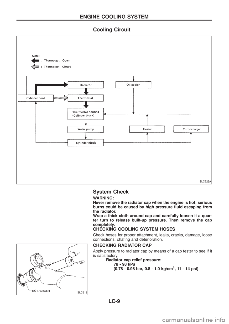
Cooling Circuit
System Check
WARNING:
Never remove the radiator cap when the engine is hot; serious
burns could be caused by high pressure ¯uid escaping from
the radiator.
Wrap a thick cloth around cap and carefully loosen it a quar-
ter turn to release built-up pressure. Then remove the cap
completely.
CHECKING COOLING SYSTEM HOSES
Check hoses for proper attachment, leaks, cracks, damage, loose
connections, cha®ng and deterioration.
CHECKING RADIATOR CAP
Apply pressure to radiator cap by means of a cap tester to see if it
is satisfactory.
Radiator cap relief pressure:
78-98kPa
(0.78 - 0.98 bar, 0.8 - 1.0 kg/cm
2, 11 - 14 psi)
SLC226A
SLC613
ENGINE COOLING SYSTEM
LC-9
Page 965 of 1226
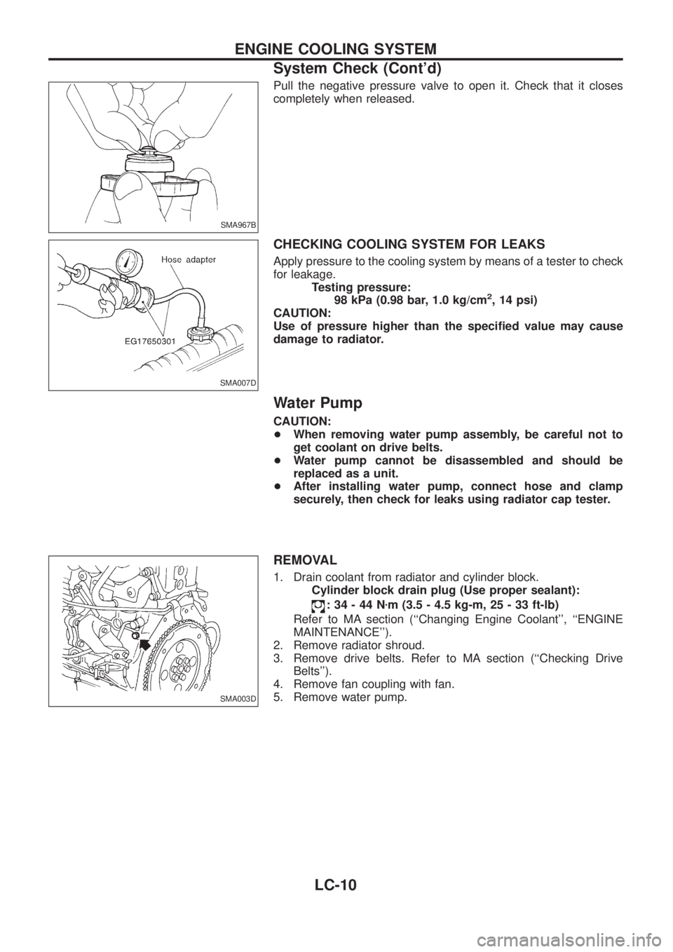
Pull the negative pressure valve to open it. Check that it closes
completely when released.
CHECKING COOLING SYSTEM FOR LEAKS
Apply pressure to the cooling system by means of a tester to check
for leakage.
Testing pressure:
98 kPa (0.98 bar, 1.0 kg/cm
2, 14 psi)
CAUTION:
Use of pressure higher than the speci®ed value may cause
damage to radiator.
Water Pump
CAUTION:
+When removing water pump assembly, be careful not to
get coolant on drive belts.
+Water pump cannot be disassembled and should be
replaced as a unit.
+After installing water pump, connect hose and clamp
securely, then check for leaks using radiator cap tester.
REMOVAL
1. Drain coolant from radiator and cylinder block.
Cylinder block drain plug (Use proper sealant):
:34-44Nzm (3.5 - 4.5 kg-m, 25 - 33 ft-lb)
Refer to MA section (``Changing Engine Coolant'', ``ENGINE
MAINTENANCE'').
2. Remove radiator shroud.
3. Remove drive belts. Refer to MA section (``Checking Drive
Belts'').
4. Remove fan coupling with fan.
5. Remove water pump.
SMA967B
SMA007D
SMA003D
ENGINE COOLING SYSTEM
System Check (Cont'd)
LC-10
Page 966 of 1226
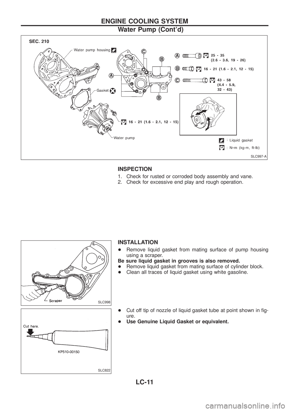
INSPECTION
1. Check for rusted or corroded body assembly and vane.
2. Check for excessive end play and rough operation.
INSTALLATION
+Remove liquid gasket from mating surface of pump housing
using a scraper.
Be sure liquid gasket in grooves is also removed.
+Remove liquid gasket from mating surface of cylinder block.
+Clean all traces of liquid gasket using white gasoline.
+Cut off tip of nozzle of liquid gasket tube at point shown in ®g-
ure.
+Use Genuine Liquid Gasket or equivalent.
SLC997-A
SLC998
SLC822
ENGINE COOLING SYSTEM
Water Pump (Cont'd)
LC-11
Page 967 of 1226
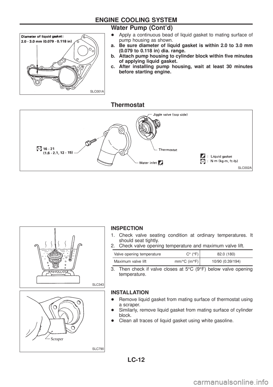
+Apply a continuous bead of liquid gasket to mating surface of
pump housing as shown.
a. Be sure diameter of liquid gasket is within 2.0 to 3.0 mm
(0.079 to 0.118 in) dia. range.
b. Attach pump housing to cylinder block within ®ve minutes
of applying liquid gasket.
c. After installing pump housing, wait at least 30 minutes
before starting engine.
Thermostat
INSPECTION
1. Check valve seating condition at ordinary temperatures. It
should seat tightly.
2. Check valve opening temperature and maximum valve lift.
Valve opening temperature CÉ (ÉF) 82.0 (180)
Maximum valve lift mm/ÉC (in/ÉF) 10/90 (0.39/194)
3. Then check if valve closes at 5ÉC (9ÉF) below valve opening
temperature.
INSTALLATION
+Remove liquid gasket from mating surface of thermostat using
a scraper.
+Similarly, remove liquid gasket from mating surface of cylinder
block.
+Clean all traces of liquid gasket using white gasoline.
SLC001A
SLC002A
SLC343
SLC790
Scraper
ENGINE COOLING SYSTEM
Water Pump (Cont'd)
LC-12
Page 968 of 1226
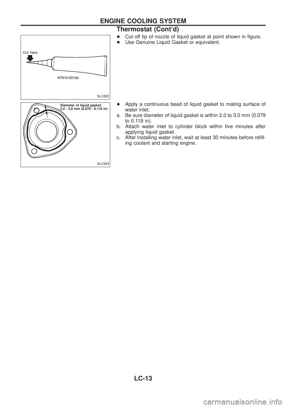
+Cut off tip of nozzle of liquid gasket at point shown in ®gure.
+Use Genuine Liquid Gasket or equivalent.
+Apply a continuous bead of liquid gasket to mating surface of
water inlet.
a. Be sure diameter of liquid gasket is within 2.0 to 3.0 mm (0.079
to 0.118 in).
b. Attach water inlet to cylinder block within ®ve minutes after
applying liquid gasket.
c. After installing water inlet, wait at least 30 minutes before re®ll-
ing coolant and starting engine.
SLC822
SLC824 Diameter of liquid gasket:
2.0 - 3.0 mm (0.079 - 0.118 in)
ENGINE COOLING SYSTEM
Thermostat (Cont'd)
LC-13
Page 969 of 1226
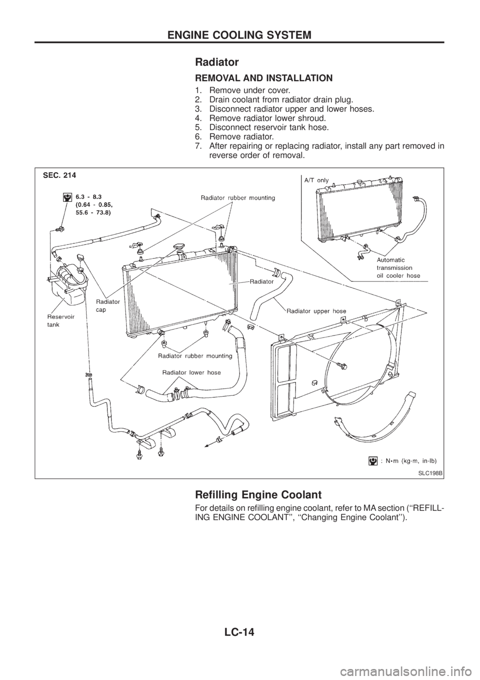
Radiator
REMOVAL AND INSTALLATION
1. Remove under cover.
2. Drain coolant from radiator drain plug.
3. Disconnect radiator upper and lower hoses.
4. Remove radiator lower shroud.
5. Disconnect reservoir tank hose.
6. Remove radiator.
7. After repairing or replacing radiator, install any part removed in
reverse order of removal.
Re®lling Engine Coolant
For details on re®lling engine coolant, refer to MA section (``REFILL-
ING ENGINE COOLANT'', ``Changing Engine Coolant'').
SLC198B
ENGINE COOLING SYSTEM
LC-14