Page 1100 of 1226
SRA813A
REAR AXLE AND REAR SUSPENSION
RA-4
Page 1101 of 1226
Rear Axle and Rear Suspension Parts
Check rear axle and rear suspension parts for excessive play, wear
or damage.
+Shake each rear wheel to check for excessive play.
+Retighten all nuts and bolts to the speci®ed torque.
Tightening torque:
Refer to REAR SUSPENSION, RA-12.
+Check shock absorber for oil leakage or other damage.
+Check shock absorber bushing for excessive wear or other
damage.
Rear Wheel Bearing
+Check that wheel bearings operate smoothly.
+Check axial end play.
Axial end play:
0mm(0in)
SMA525A
SRA814A
SRA755A
ON-VEHICLE SERVICE
RA-5
Page 1108 of 1226
SRA819A
REAR SUSPENSION
RA-12
Page 1109 of 1226
Removal and Installation
+Support axle and suspension components with a suitable jack
and block.
+Disconnect brake hydraulic line and parking brake cables at
back plates.
CAUTION:
+Use ¯are nut wrench when removing or installing brake
tubes.
+Before removing the rear suspension assembly, discon-
nect the ABS wheel sensor from the assembly. Then move
it away from the rear suspension assembly. Failure to do
so may result in damage to the sensor wires and the sen-
sor becoming inoperative.
+Remove stabilizer bar from body.
+Remove upper links and lower links from body.
+Remove panhard rod from body.
+Disconnect rear end of propeller shaft. Refer to PD section.
+Remove upper end nuts of shock absorber.
SRA825A
SBR820BA
REAR SUSPENSION
RA-13
Page 1110 of 1226

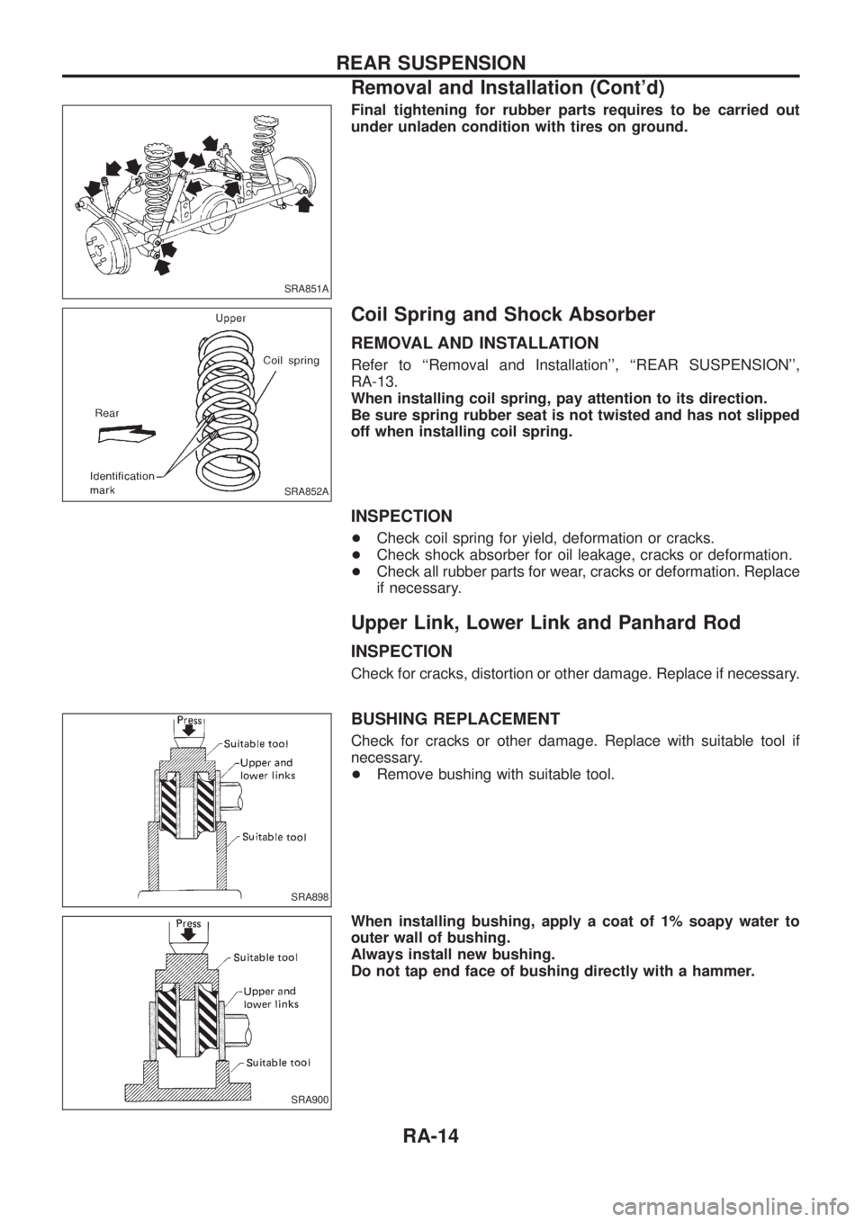
Final tightening for rubber parts requires to be carried out
under unladen condition with tires on ground.
Coil Spring and Shock Absorber
REMOVAL AND INSTALLATION
Refer to ``Removal and Installation'', ``REAR SUSPENSION'',
RA-13.
When installing coil spring, pay attention to its direction.
Be sure spring rubber seat is not twisted and has not slipped
off when installing coil spring.
INSPECTION
+Check coil spring for yield, deformation or cracks.
+Check shock absorber for oil leakage, cracks or deformation.
+Check all rubber parts for wear, cracks or deformation. Replace
if necessary.
Upper Link, Lower Link and Panhard Rod
INSPECTION
Check for cracks, distortion or other damage. Replace if necessary.
BUSHING REPLACEMENT
Check for cracks or other damage. Replace with suitable tool if
necessary.
+Remove bushing with suitable tool.
When installing bushing, apply a coat of 1% soapy water to
outer wall of bushing.
Always install new bushing.
Do not tap end face of bushing directly with a hammer.
SRA851A
SRA852A
SRA898
SRA900
REAR SUSPENSION
Removal and Installation (Cont'd)
RA-14
Page 1111 of 1226
INSTALLATION
When installing each link, pay attention to direction of nuts
and bolts.
When installing each rubber part, ®nal tightening must be car-
ried out under unladen condition with tires on ground.
Stabilizer Bar
REMOVAL AND INSTALLATION
+When removing and installing stabilizer bar, ®x portion A.
+Install stabilizer bar with ball joint socket properly placed.
SRA766A
SFA449BA
REAR SUSPENSION
Upper Link, Lower Link and Panhard Rod
(Cont'd)
RA-15
Page 1121 of 1226
General Speci®cations
Suspension type 5-link type rigid with coil spring
Shock absorber type Double-acting hydraulic
Stabilizer Standard equipment
Inspection and Adjustment
WHEEL BEARING
Total end play mm (in) 0 (0)
Wheel bearing preload at bearing
cage bolt N (kg, lb)8.8 - 42.2 (0.9 - 4.3, 2.0 - 9.5)
SERVICE DATA AND SPECIFICATIONS (SDS)
RA-25
Page 1172 of 1226

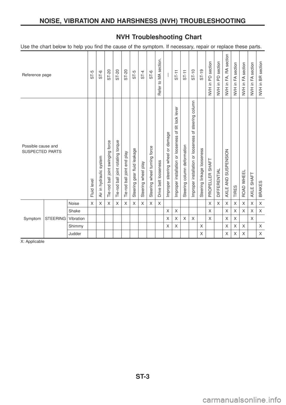
NVH Troubleshooting Chart
Use the chart below to help you ®nd the cause of the symptom. If necessary, repair or replace these parts.
Reference pageST-5
ST-6
ST-20
ST-20
ST-20
ST-5
ST-4
ST-6
Refer to MA section.
Ð
ST-11
ST-11
ST-10
ST-19
NVH in PD section
NVH in PD section
NVH in FA, RA section
NVH in FA section
NVH in FA section
NVH in FA section
NVH in BR section
Possible cause and
SUSPECTED PARTS
Fluid level
Air in hydraulic system
Tie-rod ball joint swinging force
Tie-rod ball joint rotating torque
Tie-rod ball joint end play
Steering gear ¯uid leakage
Steering wheel play
Steering wheel turning force
Drive belt looseness
Improper steering wheel or damage
Improper installation or looseness of tilt lock lever
Steering column deformation
Improper installation or looseness of steering column
Steering linkage looseness
PROPELLER SHAFT
DIFFERENTIAL
AXLE AND SUSPENSION
TIRES
ROAD WHEEL
AXLE SHAFT
BRAKES
Symptom STEERINGNoiseXXXXXXXXX XXXXXXX
Shake X X XXXXXX
VibrationXXXXXXXX
Shimmy X X X X X X X
Judder X X X X X
X: Applicable
NOISE, VIBRATION AND HARSHNESS (NVH) TROUBLESHOOTING
ST-3