Page 1006 of 1226
Engine Maintenance
INSPECTION AND ADJUSTMENT
Drive belt de¯ection
Unit: mm (in)
Drive beltsUsed belt de¯ection
De¯ection of
new belt
LimitDe¯ection
after adjust-
ment
Alternator
With air condi-
tioner compressor17 (0.67)12-14
(0.47 - 0.55)9-11
(0.35 - 0.43)
Without air condi-
tioner compressor11 (0.43)7-9
(0.28 - 0.35)6-8
(0.24 - 0.31)
Power steering oil
pump14 (0.55)10-12
(0.39 - 0.47)9-11
(0.35 - 0.43)
Applied pushing force 98 N (10 kg, 22 lb)
Engine oil capacity (Re®ll capacity)
Unit:!(Imp qt)
With oil ®lter change 6.4 (5-5/8)
Without oil ®lter change 5.8 (5-1/8)
Coolant capacity (Re®ll capacity)
With reservoir tank
Unit:!(Imp qt)
With rear heater Without rear heater
RHD 12.9 (11-3/8) 11.8 (10-3/8)
LHD 12.7 (11-1/8) 11.6 (10-1/4)
Reservoir tank 2.4 (2-1/8)
Chassis and Body Maintenance
INSPECTION AND ADJUSTMENT
Wheel balance
Maximum allowable
unbalanceDynamic
(At rim ¯ange)
g (oz)10 (0.35) (one side)
Static g (oz) 20 (0.71)
SERVICE DATA AND SPECIFICATIONS (SDS)
MA-29
Page 1169 of 1226

STEERING SYSTEM
SECTION
ST
CONTENTS
PRECAUTIONS AND PREPARATION............................1
Supplemental Restraint System (SRS) ``AIR
BAG'' and ``SEAT BELT PRE-TENSIONER''...............1
Precautions for Steering System .................................1
Special Service Tools ..................................................1
NOISE, VIBRATION AND HARSHNESS (NVH)
TROUBLESHOOTING.....................................................3
NVH Troubleshooting Chart.........................................3
ON-VEHICLE SERVICE..................................................4
Checking Steering Wheel Play ....................................4
Checking Neutral Position on Steering Wheel ............4
Front Wheel Turning Angle ..........................................4
Checking and Adjusting Drive Belts ............................5
Checking Fluid Level ...................................................5
Checking Fluid Leakage ..............................................5
Bleeding Hydraulic System..........................................6
Checking Steering Wheel Turning Force ....................6
Checking Hydraulic System.........................................6
STEERING WHEEL AND STEERING COLUMN............8
Removal and Installation .............................................8
Disassembly and Assembly .......................................10Inspection................................................................... 11
POWER STEERING SYSTEM (Model: PB69K)..........12
Description .................................................................12
POWER STEERING GEAR (Model: PB69K)...............13
Removal and Installation ...........................................13
Inspection...................................................................13
POWER STEERING OIL PUMP....................................15
Removal and Installation ...........................................15
Disassembly and Assembly .......................................16
Pre-disassembly Inspection .......................................16
Inspection...................................................................17
Disassembly...............................................................17
Assembly ...................................................................18
STEERING LINKAGE....................................................19
Removal and Installation ...........................................19
Disassembly...............................................................20
Inspection...................................................................20
SERVICE DATA AND SPECIFICATIONS (SDS)..........22
General Speci®cations ...............................................22
Inspection and Adjustment ........................................22
ST
Page 1175 of 1226

Bleeding Hydraulic System
1. Raise front end of vehicle until wheels are clear of the ground.
2. Add ¯uid into oil tank to speci®ed level. Then, quickly turn steer-
ing wheel fully to right and left and lightly touch steering stop-
pers.
Repeat steering wheel operation until ¯uid level no longer
decreases.
3. Start engine.
Repeat step 2 above.
+Incomplete air bleeding will cause the following to occur. When
this happens, bleed air again.
a. Air bubbles in reservoir tank
b. Clicking noise in oil pump
c. Excessive buzzing in oil pump
Fluid noise may occur in the valve or oil pump. This is common
when the vehicle is stationary or while turning steering wheel
slowly. This does not affect performance or durability of the system.
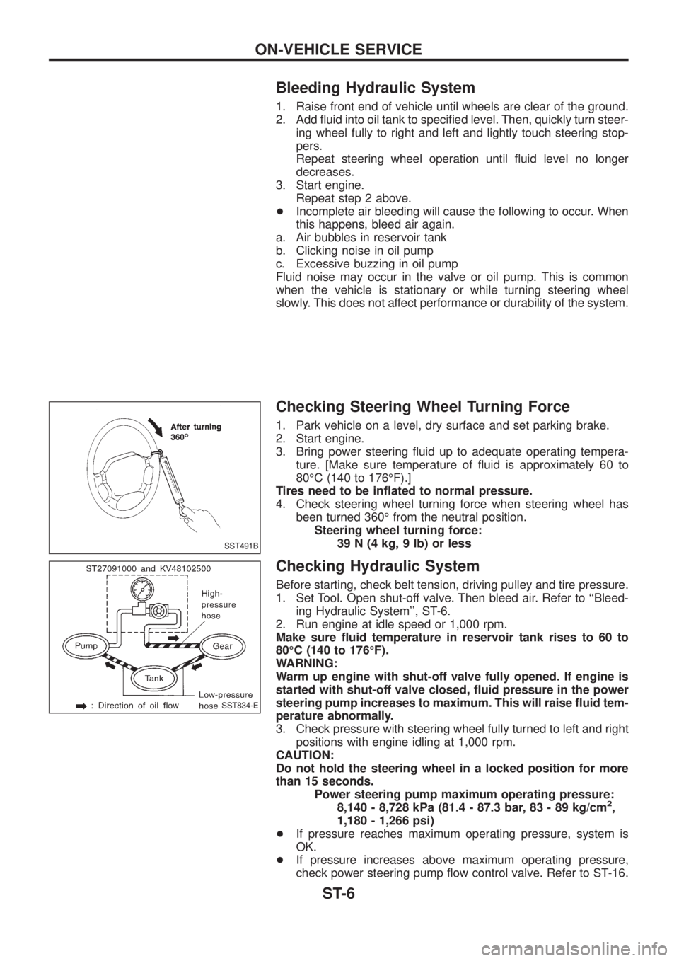
Checking Steering Wheel Turning Force
1. Park vehicle on a level, dry surface and set parking brake.
2. Start engine.
3. Bring power steering ¯uid up to adequate operating tempera-
ture. [Make sure temperature of ¯uid is approximately 60 to
80ÉC (140 to 176ÉF).]
Tires need to be in¯ated to normal pressure.
4. Check steering wheel turning force when steering wheel has
been turned 360É from the neutral position.
Steering wheel turning force:
39 N (4 kg, 9 lb) or less
Checking Hydraulic System
Before starting, check belt tension, driving pulley and tire pressure.
1. Set Tool. Open shut-off valve. Then bleed air. Refer to ``Bleed-
ing Hydraulic System'', ST-6.
2. Run engine at idle speed or 1,000 rpm.
Make sure ¯uid temperature in reservoir tank rises to 60 to
80ÉC (140 to 176ÉF).
WARNING:
Warm up engine with shut-off valve fully opened. If engine is
started with shut-off valve closed, ¯uid pressure in the power
steering pump increases to maximum. This will raise ¯uid tem-
perature abnormally.
3. Check pressure with steering wheel fully turned to left and right
positions with engine idling at 1,000 rpm.
CAUTION:
Do not hold the steering wheel in a locked position for more
than 15 seconds.
Power steering pump maximum operating pressure:
8,140 - 8,728 kPa (81.4 - 87.3 bar, 83 - 89 kg/cm
2,
1,180 - 1,266 psi)
+If pressure reaches maximum operating pressure, system is
OK.
+If pressure increases above maximum operating pressure,
check power steering pump ¯ow control valve. Refer to ST-16.
SST491B
SST834-E
ON-VEHICLE SERVICE
ST-6
Page 1176 of 1226
4. If power steering pressure is below the maximum operating
pressure, slowly close shut-off valve and check pressure again.
CAUTION:
Do not close shut-off valve for more than 15 seconds.
+If pressure increases to maximum operating pressure, gear is
damaged. Refer to ``Removal and Installation'', ST-13.
+If pressure remains below maximum operating pressure, pump
is damaged. Refer to ``Disassembly'', ST-17.
5. After checking hydraulic system, remove Tool and add ¯uid as
necessary. Then completely bleed air out of system. Refer to
ST-6.
ON-VEHICLE SERVICE
Checking Hydraulic System (Cont'd)
ST-7
Page 1181 of 1226
Description
CAUTION:
+Parts which can be disassembled are strictly limited. Never
disassemble parts other than those speci®ed.
+Disassemble in as clean a place as possible.
+Clean your hands before disassembly.
+Do not use rags; use nylon cloths or paper towels.
+Follow the procedures and cautions indicated in the Ser-
vice Manual.
SST762C
POWER STEERING SYSTEM (Model: PB69K)
ST-12
Page 1182 of 1226
Removal and Installation
Before removal, clean gear housing and oil pump exteriors
using a steam cleaner. Then dry with compressed air.
+Plug openings of gear housing, and securely locate hose con-
nectors at a position higher than oil pump and cover with paper
towels.
+Be extremely careful to prevent entry of foreign matter into
hoses through connectors.
+When installing pitman arm, align four grooves of pitman arm
serrations with four projections of sector shaft serrations, and
install and tighten lock washer and nut.
Inspection
Do not disassemble for power steering gear assembly.
TURNING TORQUE MEASUREMENT
1. Measure turning torque at 360É position.
a. Install steering gear on Tool.
SST774C
SST040-A
POWER STEERING GEAR (Model: PB69K)
ST-13
Page 1183 of 1226
b. Turn stub shaft all the way to right and left several times.
c. Measure turning torque at 360É position from straight-ahead
position with Tools.
Turning torque at 360É
0.15 - 0.78 Nzm (1.5 - 8.0 kg-cm, 1.3 - 6.9 in-lb)
2. Measure turning torque at straight-ahead position.
Straight-ahead position is a position where stub shaft is
turned 2.14 turns (two full turns and 50É) from lock position.
Turning torque at straight-ahead position:
0.2 - 0.5 Nzm (2 - 5 kg-cm, 1.7 - 4.3 in-lb)
higher than turning torque at 360É
Maximum turning torque:
0.44 - 1.18 Nzm (4.5 - 12 kg-cm, 3.9 - 10.4 in-lb)
3. Check sector shaft end play in neutral position.
End play:
Less than 0.1 mm (0.004 in)
If turning torque and end play are not within speci®cations,
replace power steering gear assembly.
SST652AA
POWER STEERING GEAR (Model: PB69K)
Inspection (Cont'd)
ST-14
Page 1184 of 1226
Removal and Installation
YST001
POWER STEERING OIL PUMP
ST-15