Page 1052 of 1226
Front Oil Seal Replacement
1. Remove propeller shaft.
2. Loosen drive pinion nut.
Tool number:
KV40104000
3. Remove companion ¯ange.
4. Remove front oil seal.
5. Apply multi-purpose grease to cavity at sealing lips of oil seal.
Press front oil seal into carrier.
6. Install companion ¯ange and drive pinion nut.
7. Install propeller shaft.
Tool number: KV381025S0
PD237
SPD737
SPD738
SPD739
ON-VEHICLE SERVICE (Final Drive)
PD-10
Page 1053 of 1226
Removal
+Remove propeller shaft.
+Remove drive shaft. Refer to FA section (``FRONT AXLE Ð
Knuckle Flange'').
+Remove axle shaft.
Refer to RA section (``REAR AXLE'').
+Remove front and rear ®nal drive mounting bolts.
CAUTION:
+Be careful not to damage spline, sleeve yoke and front oil
seal when removing propeller shaft.
+Before removing the ®nal drive assembly or rear axle
assembly, disconnect the ABS sensor harness connector
from the assembly and move it away from the ®nal drive/
rear axle assembly area. Failure to do so may result in the
sensor wires being damaged and the sensor becoming
inoperative.
Installation
+Fill ®nal drive with recommended gear oil.
+Pay attention to the direction of gasket.
SPD103
SPD123
SPD767
REMOVAL AND INSTALLATION
PD-11
Page 1093 of 1226

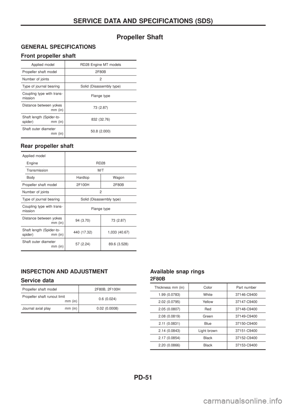
Propeller Shaft
GENERAL SPECIFICATIONS
Front propeller shaft
Applied model RD28 Engine MT models
Propeller shaft model 2F80B
Number of joints 2
Type of journal bearing Solid (Disassembly type)
Coupling type with trans-
missionFlange type
Distance between yokes
mm (in)73 (2.87)
Shaft length (Spider-to-
spider) mm (in)832 (32.76)
Shaft outer diameter
mm (in)50.8 (2.000)
Rear propeller shaft
Applied model
Engine RD28
Transmission M/T
Body Hardtop Wagon
Propeller shaft model 2F100H 2F80B
Number of joints 2
Type of journal bearing Solid (Disassembly type)
Coupling type with trans-
missionFlange type
Distance between yokes
mm (in)94 (3.70) 73 (2.87)
Shaft length (Spider-to-
spider) mm (in)440 (17.32) 1,033 (40.67)
Shaft outer diameter
mm (in)57 (2.24) 89.6 (3.528)
INSPECTION AND ADJUSTMENT
Service data
Propeller shaft model 2F80B, 2F100H
Propeller shaft runout limit
mm (in)0.6 (0.024)
Journal axial play mm (in) 0.02 (0.0008)
Available snap rings
2F80B
Thickness mm (in) Color Part number
1.99 (0.0783) White 37146-C9400
2.02 (0.0795) Yellow 37147-C9400
2.05 (0.0807) Red 37148-C9400
2.08 (0.0819) Green 37149-C9400
2.11 (0.0831) Blue 37150-C9400
2.14 (0.0843) Light brown 37151-C9400
2.17 (0.0854) Black 37152-C9400
2.20 (0.0866) Black 37153-C9400
SERVICE DATA AND SPECIFICATIONS (SDS)
PD-51
Page 1094 of 1226

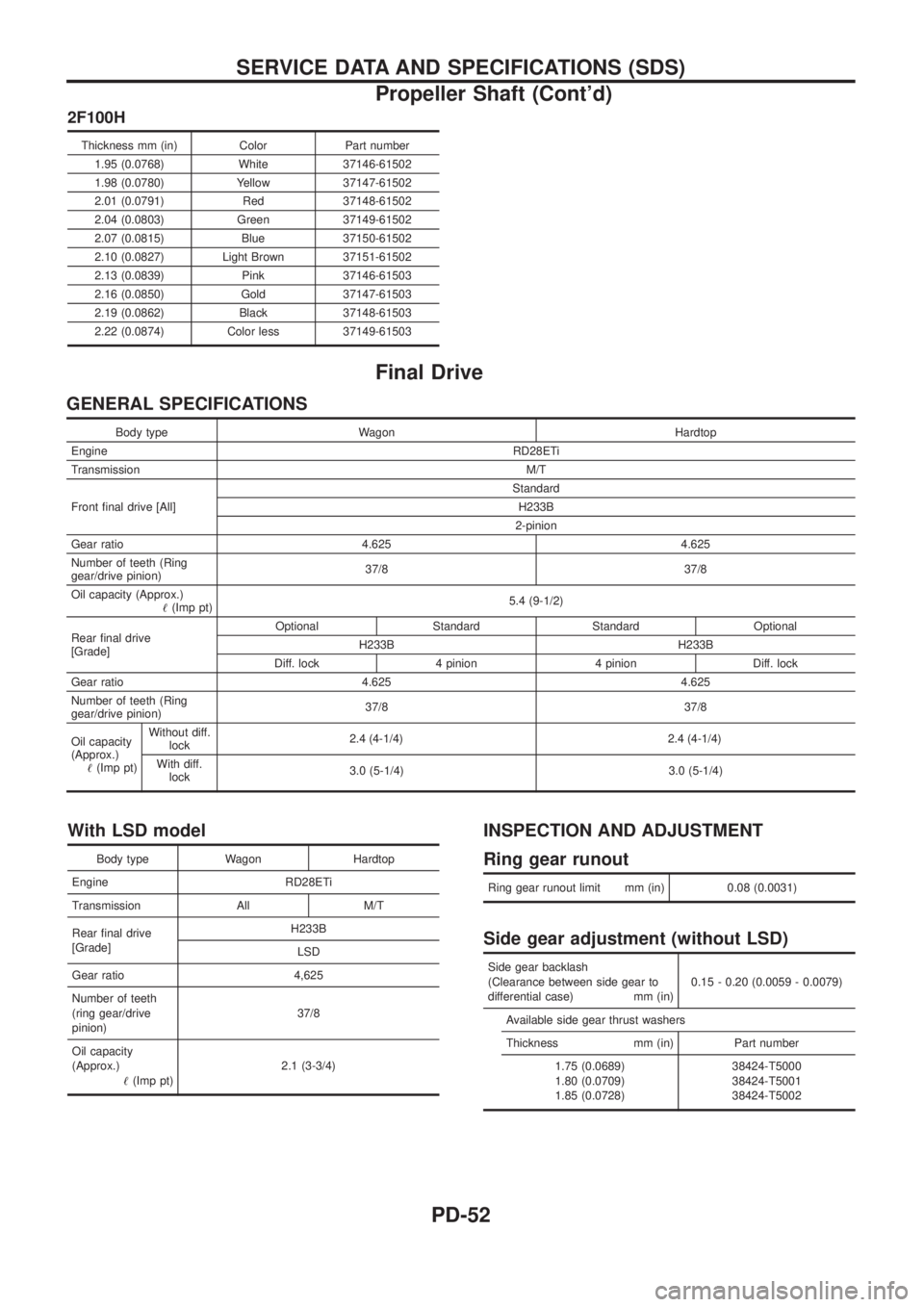
2F100H
Thickness mm (in) Color Part number1.95 (0.0768) White 37146-61502
1.98 (0.0780) Yellow 37147-61502
2.01 (0.0791) Red 37148-61502
2.04 (0.0803) Green 37149-61502
2.07 (0.0815) Blue 37150-61502
2.10 (0.0827) Light Brown 37151-61502
2.13 (0.0839) Pink 37146-61503
2.16 (0.0850) Gold 37147-61503
2.19 (0.0862) Black 37148-61503
2.22 (0.0874) Color less 37149-61503
Final Drive
GENERAL SPECIFICATIONS
Body type Wagon Hardtop
Engine RD28ETi
Transmission M/T
Front ®nal drive [All] Standard
H233B
2-pinion
Gear ratio 4.625 4.625
Number of teeth (Ring
gear/drive pinion) 37/8 37/8
Oil capacity (Approx.) !(Imp pt) 5.4 (9-1/2)
Rear ®nal drive
[Grade] Optional Standard Standard Optional
H233B H233B
Diff. lock 4 pinion 4 pinion Diff. lock
Gear ratio 4.625 4.625
Number of teeth (Ring
gear/drive pinion) 37/8 37/8
Oil capacity
(Approx.) !(Imp pt) Without diff.
lock 2.4 (4
-1/4)2.4 (4-1/4)
With diff.lock 3.0 (5-1/4) 3.0 (5-1/4)
With LSD model
Body type Wagon Hardtop
Engine RD28ETi
Transmission All M/T
Rear ®nal drive
[Grade] H233B
LSD
Gear ratio 4,625
Number of teeth
(ring gear/drive
pinion) 37/8
Oil capacity
(Approx.) !(Imp pt) 2.1 (3-3/4)
INSPECTION AND ADJUSTMENT
Ring gear runout
Ring gear runout limit mm (in) 0.08 (0.0031)
Side gear adjustment (without LSD)
Side gear backlash
(Clearance between side gear to
differential case) mm (in) 0.15 - 0.20 (0.0059 - 0.0079)
Available side gear thrust washers
Thickness mm (in) Part number 1.75 (0.0689)
1.80 (0.0709)
1.85 (0.0728) 38424-T5000
38424-T5001
38424-T5002
SERVICE DATA AND SPECIFICATIONS (SDS)
Propeller Shaft (Cont'd)
PD-52
Page 1099 of 1226

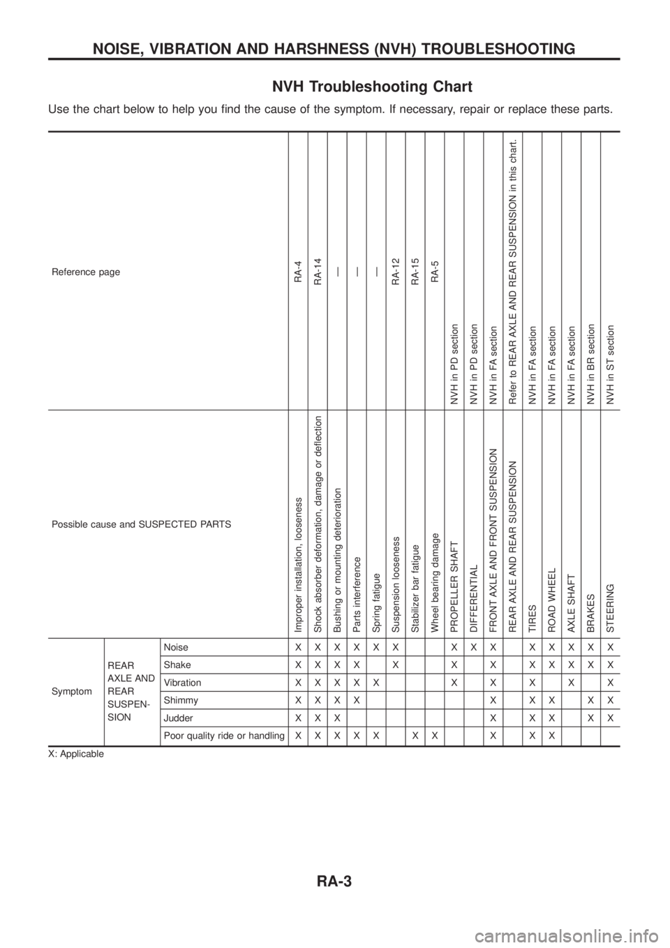
NVH Troubleshooting Chart
Use the chart below to help you ®nd the cause of the symptom. If necessary, repair or replace these parts.
Reference pageRA-4
RA-14
Ð
Ð
Ð
RA-12
RA-15
RA-5
NVH in PD section
NVH in PD section
NVH in FA section
Refer to REAR AXLE AND REAR SUSPENSION in this chart.
NVH in FA section
NVH in FA section
NVH in FA section
NVH in BR section
NVH in ST section
Possible cause and SUSPECTED PARTS
Improper installation, looseness
Shock absorber deformation, damage or de¯ection
Bushing or mounting deterioration
Parts interference
Spring fatigue
Suspension looseness
Stabilizer bar fatigue
Wheel bearing damage
PROPELLER SHAFT
DIFFERENTIAL
FRONT AXLE AND FRONT SUSPENSION
REAR AXLE AND REAR SUSPENSION
TIRES
ROAD WHEEL
AXLE SHAFT
BRAKES
STEERING
SymptomREAR
AXLE AND
REAR
SUSPEN-
SIONNoiseXXXXXX XXX XXXXX
ShakeXXXX X X X XXXXX
VibrationXXXXXXXXXX
ShimmyXXXX X XX XX
Judder X X X X X X X X
Poor quality ride or handlingXXXXX XX X XX
X: Applicable
NOISE, VIBRATION AND HARSHNESS (NVH) TROUBLESHOOTING
RA-3
Page 1198 of 1226
Replacing Oil Seal
CENTER CASE OIL SEAL
1. Remove front propeller shaft. Refer to PD section (``Removal
and Installation'', ``PROPELLER SHAFT'').
2. Remove companion ¯ange nut.
3. Remove front companion ¯ange.
4. Remove center case oil seal.
5. Install center case oil seal.
+Before installing, apply multi-purpose grease to seal lip.
6. Reinstall any part removed.
SHIFT SHAFT OIL SEAL
1. Remove transfer control lever from transfer cross shaft.
SMT091B
SMT092B
SMT093B
SMT094B
SMT251D
ON-VEHICLE SERVICE
TF-5
Page 1201 of 1226
Removal
1. Drain ¯uid and oil from transfer and transmission (M/T model
only).
2. Remove exhaust front and rear tubes. Refer to FE section
(``EXHAUST SYSTEM'').
3. Remove front and rear propeller shaft. Refer to PD section
(``Removal and Installation'', ``PROPELLER SHAFT'').
4. Disconnect neutral position switch and 4WD switch harness
connectors.
5. Remove transfer control lever from transfer cross shaft.
6. Remove transfer from transmission.
WARNING:
Support transfer while removing it.
Installation
+Apply recommended sealant to mating surface to transmission.
(M/T models only)
Recommended sealant:
Genuine anaerobic liquid gasket, Three Bond
TB1215, Loctite Part No. 51813 or equivalent
+Tighten transfer bolts.
Transfer ®xing bolts:
:32-42Nzm (3.3 - 4.3 kg-m, 24 - 31 ft-lb)
SMT251D
SMT268D
SMT176BA
REMOVAL AND INSTALLATION
TF-8
Page:
< prev 1-8 9-16 17-24