2006 NISSAN PATROL cooling system
[x] Cancel search: cooling systemPage 837 of 1226
System Description
SWITCH AND THEIR CONTROL FUNCTIONS
Knob/SwitchKnob/Switch position
Air outlet Intake air Compressor
A/C
A/CjÐ Ð ON*
Mode
jVENT Ð Ð
jB/L Ð Ð
jFOOT Ð Ð
jD/F FRE Ð
jDEF FRE ON*
jÐÐÐ
*: Compressor is operated by dual-pressure switch.
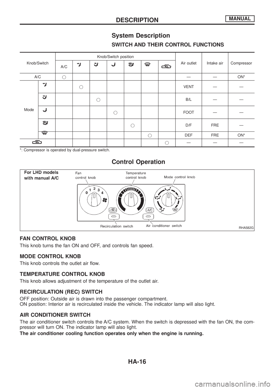
Control Operation
FAN CONTROL KNOB
This knob turns the fan ON and OFF, and controls fan speed.
MODE CONTROL KNOB
This knob controls the outlet air ¯ow.
TEMPERATURE CONTROL KNOB
This knob allows adjustment of the temperature of the outlet air.
RECIRCULATION (REC) SWITCH
OFF position: Outside air is drawn into the passenger compartment.
ON position: Interior air is recirculated inside the vehicle. The indicator lamp will also light.
AIR CONDITIONER SWITCH
The air conditioner switch controls the A/C system. When the switch is depressed with the fan ON, the com-
pressor will turn ON. The indicator lamp will also light.
The air conditioner cooling function operates only when the engine is running.
RHA582G
DESCRIPTIONMANUAL
HA-16
Page 856 of 1226
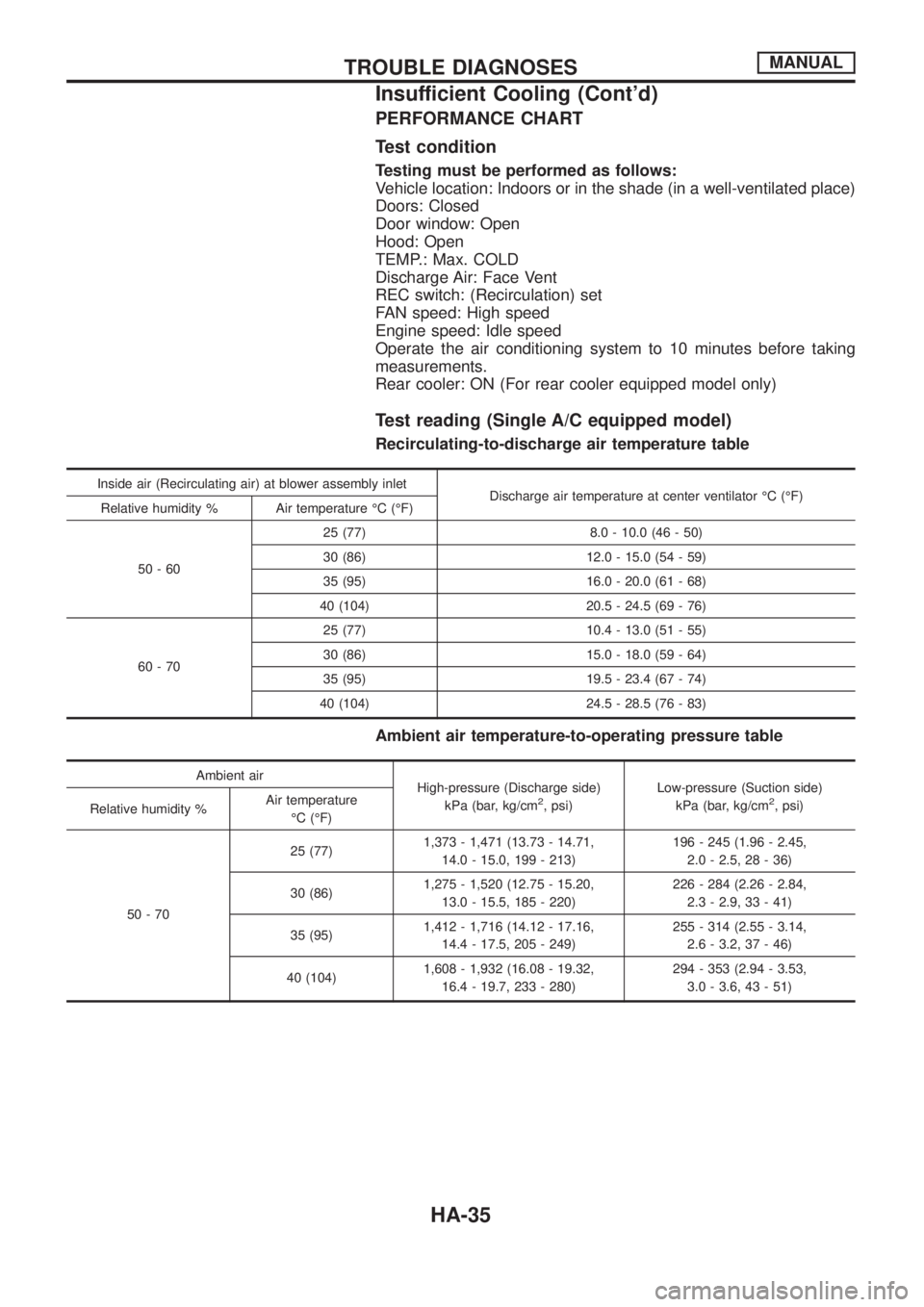
PERFORMANCE CHART
Test condition
Testing must be performed as follows:
Vehicle location: Indoors or in the shade (in a well-ventilated place)
Doors: Closed
Door window: Open
Hood: Open
TEMP.: Max. COLD
Discharge Air: Face Vent
REC switch: (Recirculation) set
FAN speed: High speed
Engine speed: Idle speed
Operate the air conditioning system to 10 minutes before taking
measurements.
Rear cooler: ON (For rear cooler equipped model only)
Test reading (Single A/C equipped model)
Recirculating-to-discharge air temperature table
Inside air (Recirculating air) at blower assembly inlet
Discharge air temperature at center ventilator ÉC (ÉF)
Relative humidity % Air temperature ÉC (ÉF)
50-6025 (77) 8.0 - 10.0 (46 - 50)
30 (86) 12.0 - 15.0 (54 - 59)
35 (95) 16.0 - 20.0 (61 - 68)
40 (104) 20.5 - 24.5 (69 - 76)
60-7025 (77) 10.4 - 13.0 (51 - 55)
30 (86) 15.0 - 18.0 (59 - 64)
35 (95) 19.5 - 23.4 (67 - 74)
40 (104) 24.5 - 28.5 (76 - 83)
Ambient air temperature-to-operating pressure table
Ambient air
High-pressure (Discharge side)
kPa (bar, kg/cm
2, psi)Low-pressure (Suction side)
kPa (bar, kg/cm2, psi)
Relative humidity %Air temperature
ÉC (ÉF)
50-7025 (77)1,373 - 1,471 (13.73 - 14.71,
14.0 - 15.0, 199 - 213)196 - 245 (1.96 - 2.45,
2.0 - 2.5, 28 - 36)
30 (86)1,275 - 1,520 (12.75 - 15.20,
13.0 - 15.5, 185 - 220)226 - 284 (2.26 - 2.84,
2.3 - 2.9, 33 - 41)
35 (95)1,412 - 1,716 (14.12 - 17.16,
14.4 - 17.5, 205 - 249)255 - 314 (2.55 - 3.14,
2.6 - 3.2, 37 - 46)
40 (104)1,608 - 1,932 (16.08 - 19.32,
16.4 - 19.7, 233 - 280)294 - 353 (2.94 - 3.53,
3.0 - 3.6, 43 - 51)
TROUBLE DIAGNOSESMANUAL
Insufficient Cooling (Cont'd)
HA-35
Page 857 of 1226
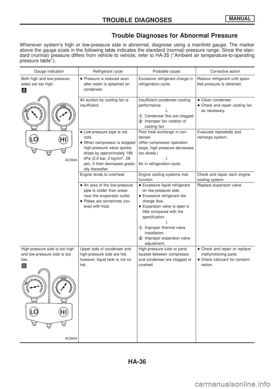
Trouble Diagnoses for Abnormal Pressure
Whenever system's high or low-pressure side is abnormal, diagnose using a manifold gauge. The marker
above the gauge scale in the following table indicates the standard (normal) pressure range. Since the stan-
dard (normal) pressure differs from vehicle to vehicle, refer to HA-35 (``Ambient air temperature-to-operating
pressure table'').
Gauge indication Refrigerant cycle Probable cause Corrective action
Both high and low-pressure
sides are too high.
AC359A
+Pressure is reduced soon
after water is splashed on
condenser.Excessive refrigerant charge in
refrigeration cycle.Reduce refrigerant until speci-
®ed pressure is obtained.
Air suction by cooling fan is
insufficient.Insufficient condenser cooling
performance.
¯
j
1Condenser ®ns are clogged.
j
2Improper fan rotation of
cooling fan.+Clean condenser.
+Check and repair cooling fan
as necessary.
+Low-pressure pipe is not
cold.
+When compressor is stopped
high-pressure value quickly
drops by approximately 196
kPa (2.0 bar, 2 kg/cm
2,28
psi). It then decreases gradu-
ally thereafter.Poor heat exchange in con-
denser.
(After compressor operation
stops, high pressure decreases
too slowly.)
¯
Air in refrigeration cycle.Evacuate repeatedly and
recharge system.
Engine tends to overheat. Engine cooling systems mal-
function.Check and repair each engine
cooling system.
+An area of the low-pressure
pipe is colder than areas
near the evaporator outlet.
+Plates are sometimes cov-
ered with frost.+Excessive liquid refrigerant
on low-pressure side.
+Excessive refrigerant dis-
charge ¯ow.
+Expansion valve is open a
little compared with the
speci®cation.
¯
j
1Improper thermal valve
installation.
j
2Improper expansion valve
adjustment.Replace expansion valve.
High-pressure side is too high
and low-pressure side is too
low.
AC360A
Upper side of condenser and
high-pressure side are hot,
however, liquid tank is not so
hot.High-pressure tube or parts
located between compressor
and condenser are clogged or
crushed.+Check and repair or replace
malfunctioning parts.
+Check lubricant for contami-
nation.
TROUBLE DIAGNOSESMANUAL
HA-36
Page 859 of 1226
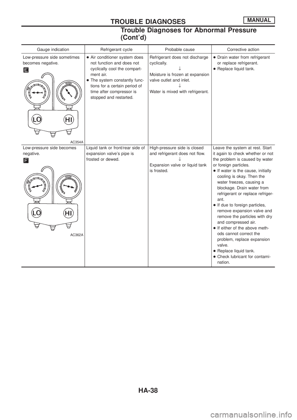
Gauge indication Refrigerant cycle Probable cause Corrective action
Low-pressure side sometimes
becomes negative.
AC354A
+Air conditioner system does
not function and does not
cyclically cool the compart-
ment air.
+The system constantly func-
tions for a certain period of
time after compressor is
stopped and restarted.Refrigerant does not discharge
cyclically.
¯
Moisture is frozen at expansion
valve outlet and inlet.
¯
Water is mixed with refrigerant.+Drain water from refrigerant
or replace refrigerant.
+Replace liquid tank.
Low-pressure side becomes
negative.
AC362A
Liquid tank or front/rear side of
expansion valve's pipe is
frosted or dewed.High-pressure side is closed
and refrigerant does not ¯ow.
¯
Expansion valve or liquid tank
is frosted.Leave the system at rest. Start
it again to check whether or not
the problem is caused by water
or foreign particles.
+If water is the cause, initially
cooling is okay. Then the
water freezes, causing a
blockage. Drain water from
refrigerant or replace refriger-
ant.
+If due to foreign particles,
remove expansion valve and
remove the particles with dry
and compressed air.
+If either of the above meth-
ods cannot correct the
problem, replace expansion
valve.
+Replace liquid tank.
+Check lubricant for contami-
nation.
TROUBLE DIAGNOSESMANUAL
Trouble Diagnoses for Abnormal Pressure
(Cont'd)
HA-38
Page 890 of 1226
How to Perform Trouble Diagnoses for Quick
and Accurate Repair
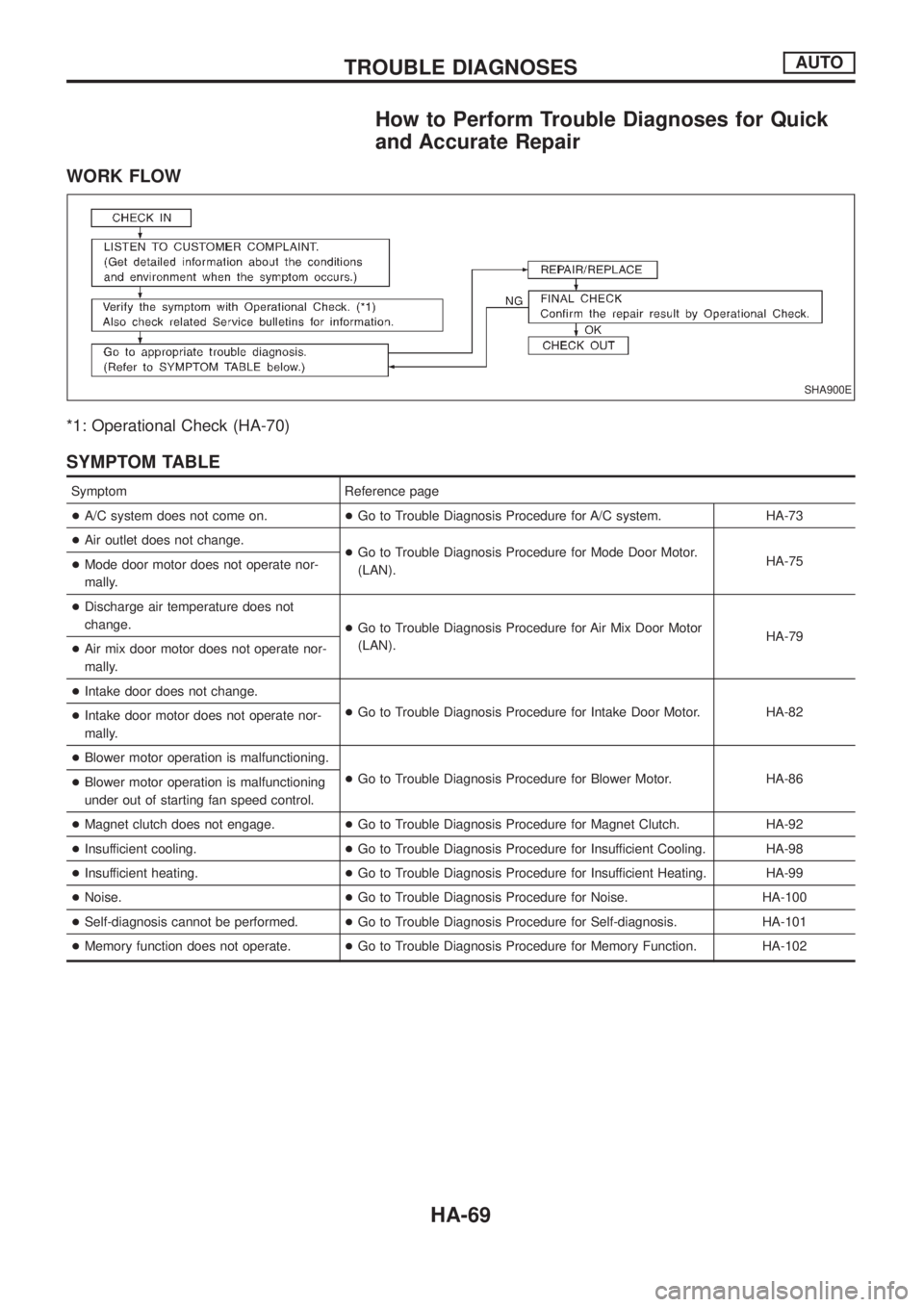
WORK FLOW
*1: Operational Check (HA-70)
SYMPTOM TABLE
Symptom Reference page
+A/C system does not come on.+Go to Trouble Diagnosis Procedure for A/C system. HA-73
+Air outlet does not change.
+Go to Trouble Diagnosis Procedure for Mode Door Motor.
(LAN).HA-75
+Mode door motor does not operate nor-
mally.
+Discharge air temperature does not
change.
+Go to Trouble Diagnosis Procedure for Air Mix Door Motor
(LAN).HA-79
+Air mix door motor does not operate nor-
mally.
+Intake door does not change.
+Go to Trouble Diagnosis Procedure for Intake Door Motor. HA-82
+Intake door motor does not operate nor-
mally.
+Blower motor operation is malfunctioning.
+Go to Trouble Diagnosis Procedure for Blower Motor. HA-86
+Blower motor operation is malfunctioning
under out of starting fan speed control.
+Magnet clutch does not engage.+Go to Trouble Diagnosis Procedure for Magnet Clutch. HA-92
+Insufficient cooling.+Go to Trouble Diagnosis Procedure for Insufficient Cooling. HA-98
+Insufficient heating.+Go to Trouble Diagnosis Procedure for Insufficient Heating. HA-99
+Noise.+Go to Trouble Diagnosis Procedure for Noise. HA-100
+Self-diagnosis cannot be performed.+Go to Trouble Diagnosis Procedure for Self-diagnosis. HA-101
+Memory function does not operate.+Go to Trouble Diagnosis Procedure for Memory Function. HA-102
SHA900E
TROUBLE DIAGNOSESAUTO
HA-69
Page 935 of 1226
Maintenance of Lubricant Quantity in
Compressor
The lubricant used to lubricate the compressor circulates through
the system with the refrigerant. Add lubricant to compressor when
replacing any component or after a large gas leakage occurred. It
is important to maintain the speci®ed amount.
If lubricant quantity is not maintained properly, the following mal-
functions may result:
+Lack of lubricant: May lead to a seized compressor
+Excessive lubricant: Inadequate cooling (thermal exchange
interference)
LUBRICANT
Name: Nissan A/C System Oil Type S
Part number: KLH00-PAGS0
CHECKING AND ADJUSTING
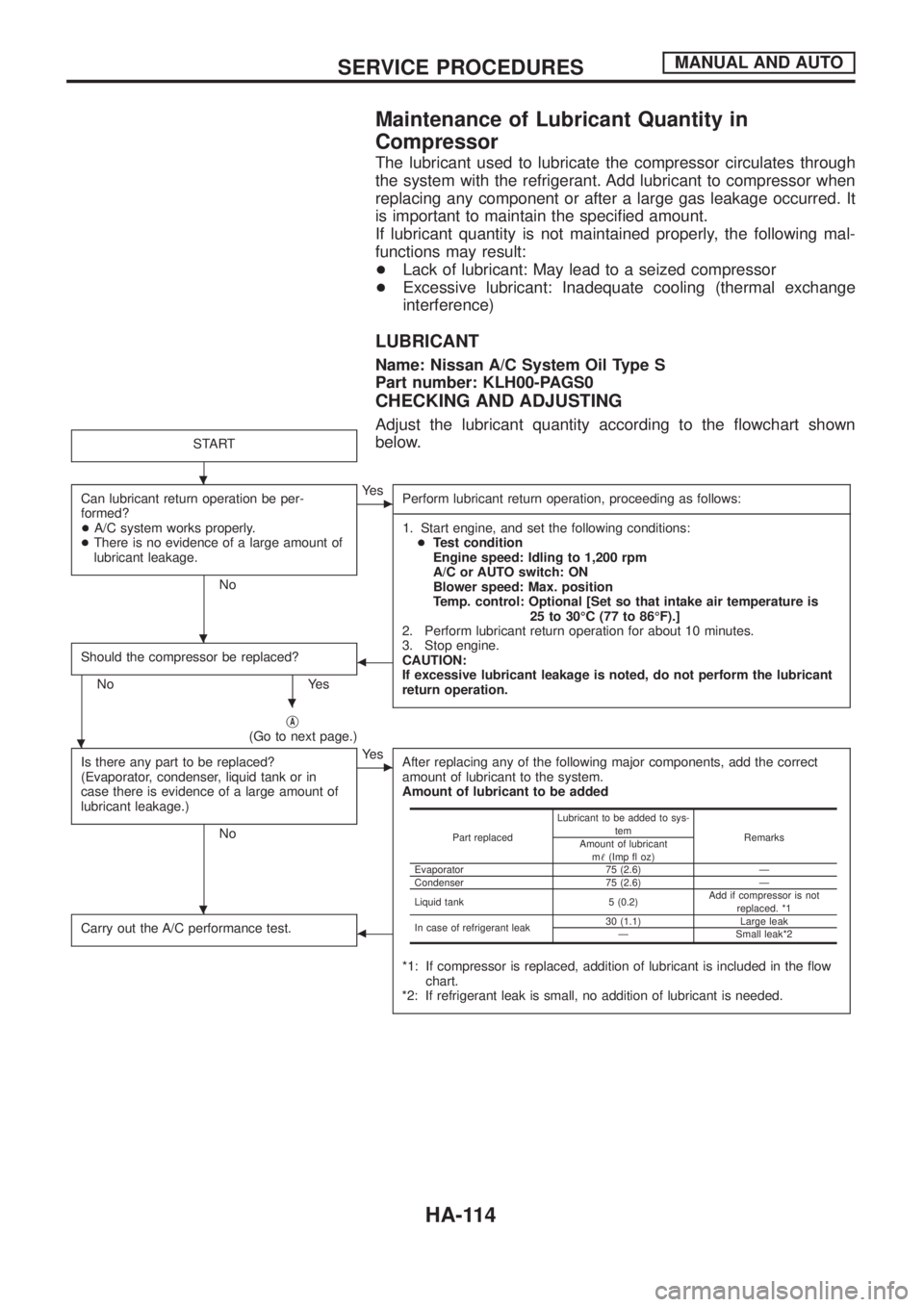
Adjust the lubricant quantity according to the ¯owchart shown
below.
START
Can lubricant return operation be per-
formed?
+A/C system works properly.
+There is no evidence of a large amount of
lubricant leakage.
No
cYe s
Perform lubricant return operation, proceeding as follows:
------------------------------------------------------------------------------------------------------------------------------------------------------------------------------------------------------------------------------------------------------------------------------------------------------------------------------------------------------------------------------------------------------------------------------------------------------------------------------------------------------------------------------------
1. Start engine, and set the following conditions:
+Test condition
Engine speed: Idling to 1,200 rpm
A/C or AUTO switch: ON
Blower speed: Max. position
Temp. control: Optional [Set so that intake air temperature is
25 to 30ÉC (77 to 86ÉF).]
2. Perform lubricant return operation for about 10 minutes.
3. Stop engine.
CAUTION:
If excessive lubricant leakage is noted, do not perform the lubricant
return operation.
Should the compressor be replaced?
No Yes
b
jA(Go to next page.)
Is there any part to be replaced?
(Evaporator, condenser, liquid tank or in
case there is evidence of a large amount of
lubricant leakage.)
No
cYe s
After replacing any of the following major components, add the correct
amount of lubricant to the system.
Amount of lubricant to be added
*1: If compressor is replaced, addition of lubricant is included in the ¯ow
chart.
*2: If refrigerant leak is small, no addition of lubricant is needed.
Carry out the A/C performance test.b
Part replacedLubricant to be added to sys-
tem
Remarks
Amount of lubricant
m!(Imp ¯ oz)
Evaporator 75 (2.6) Ð
Condenser 75 (2.6) Ð
Liquid tank 5 (0.2)Add if compressor is not
replaced. *1
In case of refrigerant leak30 (1.1) Large leak
Ð Small leak*2
.
.
.
.
.
SERVICE PROCEDURESMANUAL AND AUTO
HA-114
Page 941 of 1226
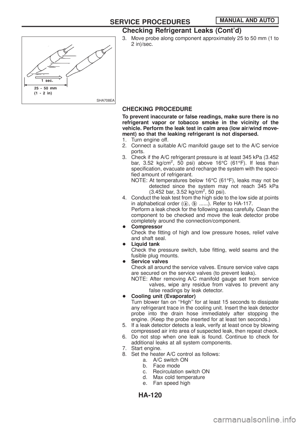
3. Move probe along component approximately 25 to 50 mm (1 to
2 in)/sec.
CHECKING PROCEDURE
To prevent inaccurate or false readings, make sure there is no
refrigerant vapor or tobacco smoke in the vicinity of the
vehicle. Perform the leak test in calm area (low air/wind move-
ment) so that the leaking refrigerant is not dispersed.
1. Turn engine off.
2. Connect a suitable A/C manifold gauge set to the A/C service
ports.
3. Check if the A/C refrigerant pressure is at least 345 kPa (3.452
bar, 3.52 kg/cm
2, 50 psi) above 16ÉC (61ÉF). If less than
speci®cation, evacuate and recharge the system with the speci-
®ed amount of refrigerant.
NOTE: At temperatures below 16ÉC (61ÉF), leaks may not be
detected since the system may not reach 345 kPa
(3.452 bar, 3.52 kg/cm
2, 50 psi).
4. Conduct the leak test from the high side to the low side at points
in alphabetical order (j
a,jb......). Refer to HA-117.
Perform a leak check for the following areas carefully. Clean the
component to be checked and move the leak detector probe
completely around the connection/component.
+Compressor
Check the ®tting of high and low pressure hoses, relief valve
and shaft seal.
+Liquid tank
Check the pressure switch, tube ®tting, weld seams and the
fusible plug mounts.
+Service valves
Check all around the service valves. Ensure service valve caps
are secured on the service valves (to prevent leaks).
NOTE: After removing A/C manifold gauge set from service
valves, wipe any residue from valves to prevent any
false readings by leak detector.
+Cooling unit (Evaporator)
Turn blower fan on ``High'' for at least 15 seconds to dissipate
any refrigerant trace in the cooling unit. Insert the leak detector
probe into the drain hose immediately after stopping the
engine. (Keep the probe inserted for at least ten seconds.)
5. If a leak detector detects a leak, verify at least once by blowing
compressed air into area of suspected leak, then repeat check.
6. Do not stop when one leak is found. Continue to check for
additional leaks at all system components.
7. Start engine.
8. Set the heater A/C control as follows:
a. A/C switch ON
b. Face mode
c. Recirculation switch ON
d. Max cold temperature
e. Fan speed high
SHA708EA
SERVICE PROCEDURESMANUAL AND AUTO
Checking Refrigerant Leaks (Cont'd)
HA-120
Page 950 of 1226

Combination meter........................................EL-102
Combination switch .........................................EL-57
Combustion chamber replacement ................EM-32
Compass .......................................................EL-116
Compression pressure ...................................EM-10
Compressor special service tool ......................HA-6
Connecting rod...............................................EM-47
Connecting rod...............................................EM-51
Connector inspection .......................................GI-17
Console box - See Instrument panel ..............BT-11
Control lever (Transfer) .....................................TF-9
Control sleeve position sensor .......................EC-86
Coolant mixture ratio ......................................MA-11
Coolant replacement ......................................MA-14
Cooling circuit (engine) .....................................LC-9
Cooling fan control .......................................EC-112
Cooling fan motor .........................................EC-120
Cooling fan relay ..........................................EC-120
Cooling fan......................................................LC-15
Counter gear (M/T).........................................MT-10
Counter gear (Transfer) ..................................TF-11
Coupling sleeve (M/T) ....................................MT-10
Crankcase emission control system -
See Positive crankcase ventilation.............EC-21
Crankcase ventilation system - See
Positive crankcase ventilation ....................EC-21
Crankshaft position sensor (TDC)................EC-143
Crankshaft ......................................................EM-50
Cylinder block ..........................................EM-45, 48
Cylinder head .................................................EM-28
D
D/LOCK - Wiring diagram .............................EL-205
DEF - Wiring diagram ...................................EL-159
DEICER - Wiring diagram.............................EL-167
DTRL - Wiring diagram ...................................EL-67
Data link connector for Consult......................EC-36
Daytime light system.......................................EL-65
Diagnosis sensor unit .....................................RS-12
Diagnostic trouble code (DTC) for
ECCS OBD system ....................................EC-30
Differential carrier assembly...........................PD-31
Differential carrier disassembly ......................PD-14
Differential gear oil replacement ....................MA-22
Dimensions ......................................................GI-38
Dome light - See Interior lamp .......................EL-93
Door glass .........................................................BT-9
Door lock ...........................................................BT-9
Door mirror ......................................................BT-46
Door trim .........................................................BT-18
Door, front .........................................................BT-9
Door, rear ........................................................BT-10
Drive belt inspection ......................................MA-12
Drive chain (Transfer) .....................................TF-11
Drive pinion diff. inspection ............................PD-19
Drive pinion height .........................................PD-27
Drive shaft (front) ............................................FA-23
Dual pressure switch ......................................HA-11Dual pressure switch ......................................HA-97
E
ECCS basic inspection...................................EC-46
ECCS circuit diagram .....................................EC-11
ECCS component parts location ......................EC-8
ECCS on board diagnostic system ................EC-30
ECCS symptom matrix chart..........................EC-48
ECCS system diagram and chart ..................EC-12
ECCS-D control module .........................EC-54, 110
ECM input/output signal .................................EC-54
ECTS - Wiring diagram ..................................EC-78
EGR control (EGRC) - solenoid valve .........EC-155
EGR control valve ........................................EC-161
EGRC/V - Wiring diagram ............................EC-155
Electric governor ....................................EC-95, 148
Electric sunroof .............................................EL-186
Electrical diagnoses.........................................GI-20
Electrical unit.................................................EL-321
Electrical units location .................................EL-269
Electronic fuel injection pump ........................EC-27
Engine compartment .......................................BT-49
Engine coolant temperature sensor
(ECTS) ........................................................EC-78
Engine oil ®lter replacement ..........................MA-14
Engine oil precautions .......................................GI-4
Engine oil replacement ..................................MA-13
Engine outer component parts ........................EM-8
Engine removal ..............................................EM-43
Engine room - See Engine
compartment ...............................................BT-49
Engine serial number ......................................GI-37
Exhaust system inspection ............................MA-20
Exhaust system ................................................FE-3
Exterior ............................................................BT-26
F
FCUT - Wiring diagram ................................EC-129
FTS - Wiring diagram ...................................EC-134
Fan control amp. ............................................HA-88
Final drive disassembly ..................................PD-14
Final drive removal and installation................PD-11
Finisher, interior - See Trim ............................BT-14
Floor trim .........................................................BT-14
Flow charts ......................................................GI-30
Fluids................................................................MA-9
Flywheel (clutch).......................................CL-13, 14
Flywheel runout..............................................EM-52
Fog lamp, rear ................................................EL-80
Fork rod (M/T) ................................................MT-12
Front axle ........................................................FA-10
Front bumper ....................................................BT-4
Front case (Transfer) ......................................TF-10
Front disc brake .............................................BR-20
Front door .........................................................BT-9
ALPHABETICAL INDEX
IDX-3