2006 NISSAN PATROL relay
[x] Cancel search: relayPage 63 of 1226
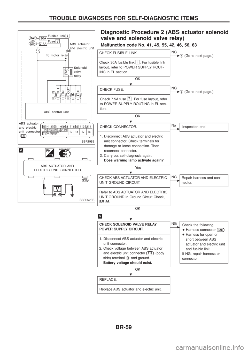
Diagnostic Procedure 2 (ABS actuator solenoid
valve and solenoid valve relay)
Malfunction code No. 41, 45, 55, 42, 46, 56, 63
CHECK FUSIBLE LINK.
- ---------------------------------------------------------------------------------------------------------------------------------------------------------------------------------------------------------------------------------------------------------------------------------------------------------------
Check 30A fusible link
i. For fusible link
layout, refer to POWER SUPPLY ROUT-
ING in EL section.
OK
cNG jA(Go to next page.)
CHECK FUSE.
- ---------------------------------------------------------------------------------------------------------------------------------------------------------------------------------------------------------------------------------------------------------------------------------------------------------------
Check 7.5A fuse
7. For fuse layout, refer
to POWER SUPPLY ROUTING in EL sec-
tion.
OK
cNG jB(Go to next page.)
CHECK CONNECTOR.
- ---------------------------------------------------------------------------------------------------------------------------------------------------------------------------------------------------------------------------------------------------------------------------------------------------------------
1. Disconnect ABS actuator and electric unit connector. Check terminals for
damage or loose connection. Then
reconnect connector.
2. Carry out self-diagnosis again. Does warning lamp activate again?
Ye s
cNo Inspection end
CHECK ABS ACTUATOR AND ELECTRIC
UNIT GROUND CIRCUIT.
- ---------------------------------------------------------------------------------------------------------------------------------------------------------------------------------------------------------------------------------------------------------------------------------------------------------------
Refer to ABS ACTUATOR AND ELECTRIC
UNIT GROUND in Ground Circuit Check,
BR-56.
OK
cNG Repair harness and con-
nector.
CHECK SOLENOID VALVE RELAY
POWER SUPPLY CIRCUIT.
- ---------------------------------------------------------------------------------------------------------------------------------------------------------------------------------------------------------------------------------------------------------------------------------------------------------------
1. Disconnect ABS actuator and electric unit connector.
2. Check voltage between ABS actuator and electric unit connector
E18(body
side) terminal j
18and ground.
Battery voltage should exist.
OK
cNG Check the following.
+Harness connector
E18
+Harness for open or
short between ABS
actuator and electric unit
and fusible link
If NG, repair harness or
connector.
REPLACE.
- ---------------------------------------------------------------------------------------------------------------------------------------------------------------------------------------------------------------------------------------------------------------------------------------------------------------
Replace ABS actuator and electric unit.
SBR198E
SBR052EB
.
.
.
.
.
TROUBLE DIAGNOSES FOR SELF-DIAGNOSTIC ITEMS
BR-59
Page 64 of 1226
jA
REPLACE.
- ---------------------------------------------------------------------------------------------------------------------------------------------------------------------------------------------------------------------------------------------------------------------------------------------------------------
Replace fusible link.
Does the fusible link blow out when
ignition switch is turned ``ON''?
Ye s
cNo Inspection end
CHECK SOLENOID VALVE RELAY
POWER SUPPLY CIRCUIT.
- ---------------------------------------------------------------------------------------------------------------------------------------------------------------------------------------------------------------------------------------------------------------------------------------------------------------
1. Disconnect ABS actuator and electric
unit connector.
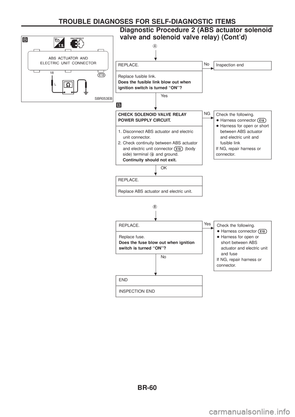
2. Check continuity between ABS actuator and electric unit connector
E18(body
side) terminal j
18and ground.
Continuity should not exit.
OK
cNG Check the following.
+Harness connector
E18
+Harness for open or short
between ABS actuator
and electric unit and
fusible link
If NG, repair harness or
connector.
REPLACE.
- ---------------------------------------------------------------------------------------------------------------------------------------------------------------------------------------------------------------------------------------------------------------------------------------------------------------
Replace ABS actuator and electric unit.
jB
REPLACE.
- ---------------------------------------------------------------------------------------------------------------------------------------------------------------------------------------------------------------------------------------------------------------------------------------------------------------
Replace fuse.
Does the fuse blow out when ignition
switch is turned ``ON''?
No
cYe s Check the following.
+Harness connector
E18
+Harness for open or
short between ABS
actuator and electric unit
and fuse
If NG, repair harness or
connector.
END
- ---------------------------------------------------------------------------------------------------------------------------------------------------------------------------------------------------------------------------------------------------------------------------------------------------------------
INSPECTION END
SBR053EB
.
.
.
.
.
TROUBLE DIAGNOSES FOR SELF-DIAGNOSTIC ITEMS
Diagnostic Procedure 2 (ABS actuator solenoid
valve and solenoid valve relay) (Cont'd)
BR-60
Page 65 of 1226
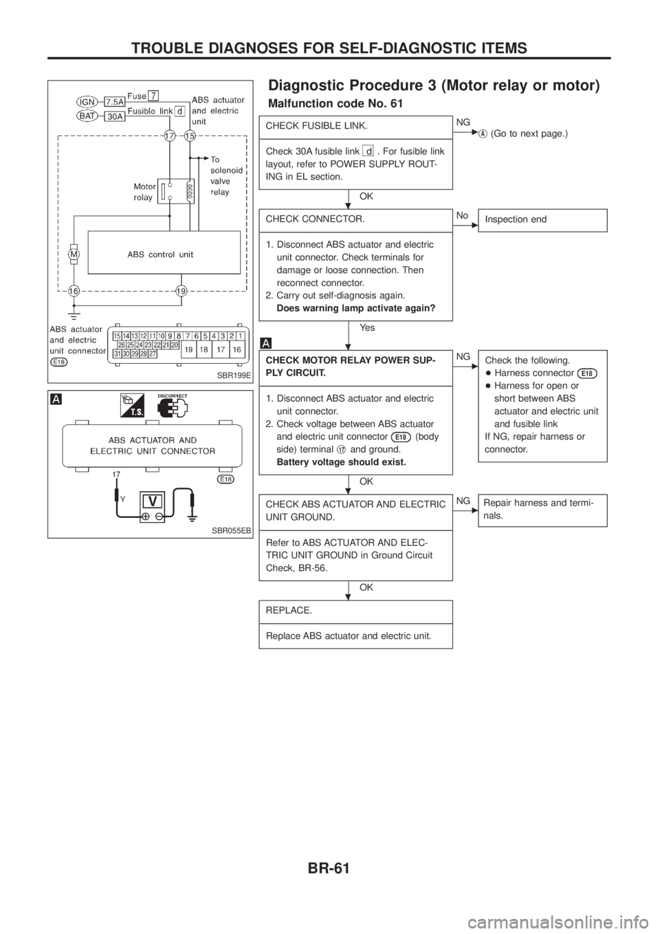
Diagnostic Procedure 3 (Motor relay or motor)
Malfunction code No. 61
CHECK FUSIBLE LINK.
- ---------------------------------------------------------------------------------------------------------------------------------------------------------------------------------------------------------------------------------------------------------------------------------------------------------------
Check 30A fusible link
d . For fusible link
layout, refer to POWER SUPPLY ROUT-
ING in EL section.
OK
cNG jA(Go to next page.)
CHECK CONNECTOR.
- ---------------------------------------------------------------------------------------------------------------------------------------------------------------------------------------------------------------------------------------------------------------------------------------------------------------
1. Disconnect ABS actuator and electric unit connector. Check terminals for
damage or loose connection. Then
reconnect connector.
2. Carry out self-diagnosis again. Does warning lamp activate again?
Ye s
cNo Inspection end
CHECK MOTOR RELAY POWER SUP-
PLY CIRCUIT.
- ---------------------------------------------------------------------------------------------------------------------------------------------------------------------------------------------------------------------------------------------------------------------------------------------------------------
1. Disconnect ABS actuator and electric unit connector.
2. Check voltage between ABS actuator and electric unit connector
E18(body
side) terminal j
17and ground.
Battery voltage should exist.
OK
cNG Check the following.
+Harness connector
E18
+Harness for open or
short between ABS
actuator and electric unit
and fusible link
If NG, repair harness or
connector.
CHECK ABS ACTUATOR AND ELECTRIC
UNIT GROUND.
- ---------------------------------------------------------------------------------------------------------------------------------------------------------------------------------------------------------------------------------------------------------------------------------------------------------------
Refer to ABS ACTUATOR AND ELEC-
TRIC UNIT GROUND in Ground Circuit
Check, BR-56.
OK
cNG Repair harness and termi-
nals.
REPLACE.
- ---------------------------------------------------------------------------------------------------------------------------------------------------------------------------------------------------------------------------------------------------------------------------------------------------------------
Replace ABS actuator and electric unit.
SBR199E
SBR055EB
.
.
.
.
TROUBLE DIAGNOSES FOR SELF-DIAGNOSTIC ITEMS
BR-61
Page 66 of 1226
jA
REPLACE.
- ---------------------------------------------------------------------------------------------------------------------------------------------------------------------------------------------------------------------------------------------------------------------------------------------------------------
Replace fusible link.
Does the fusible link blow out when
ignition switch is turned ``ON''?
Ye s
cNo Inspection end
CHECK ABS ACTUATOR MOTOR
POWER SUPPLY CIRCUIT.
- ---------------------------------------------------------------------------------------------------------------------------------------------------------------------------------------------------------------------------------------------------------------------------------------------------------------
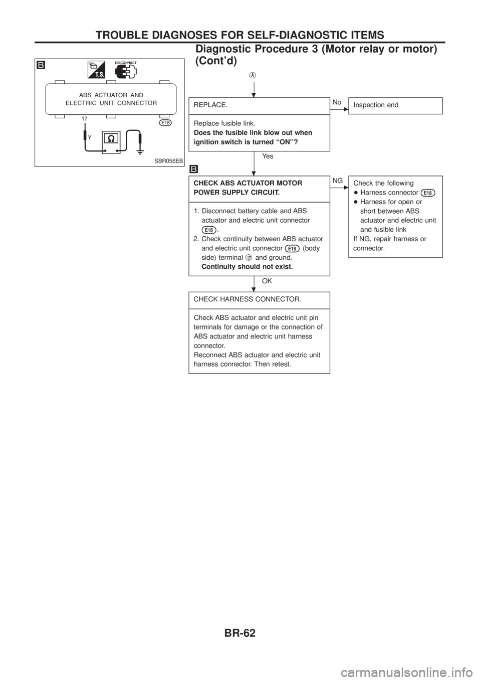
1. Disconnect battery cable and ABS actuator and electric unit connector
E18.
2. Check continuity between ABS actuator and electric unit connector
E18(body
side) terminal j
17and ground.
Continuity should not exist.
OK
cNG Check the following
+Harness connector
E18
+Harness for open or
short between ABS
actuator and electric unit
and fusible link
If NG, repair harness or
connector.
CHECK HARNESS CONNECTOR.
- ---------------------------------------------------------------------------------------------------------------------------------------------------------------------------------------------------------------------------------------------------------------------------------------------------------------
Check ABS actuator and electric unit pin
terminals for damage or the connection of
ABS actuator and electric unit harness
connector.
Reconnect ABS actuator and electric unit
harness connector. Then retest.
SBR056EB
.
.
.
TROUBLE DIAGNOSES FOR SELF-DIAGNOSTIC ITEMS
Diagnostic Procedure 3 (Motor relay or motor)
(Cont'd)
BR-62
Page 165 of 1226
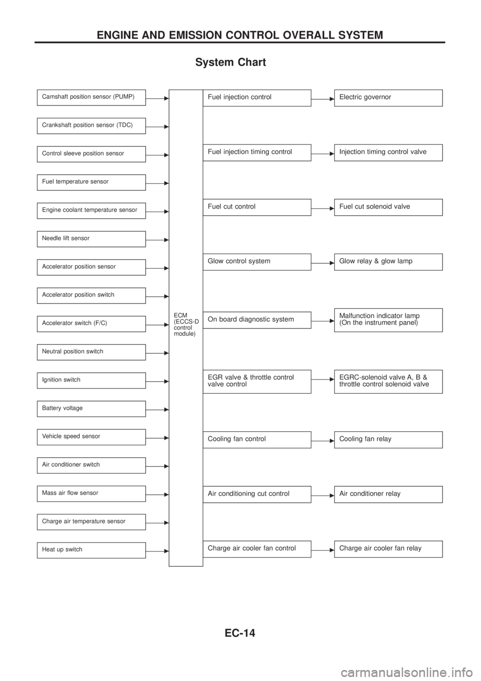
System Chart
Camshaft position sensor (PUMP)c
ECM
(ECCS-D
control
module)
Crankshaft position sensor (TDC)c
Control sleeve position sensorc
Fuel temperature sensorc
Engine coolant temperature sensorc
Needle lift sensorc
Accelerator position sensorc
Accelerator position switchc
Accelerator switch (F/C)c
Neutral position switchc
Ignition switchc
Battery voltagec
Vehicle speed sensorc
Air conditioner switchc
Mass air ¯ow sensorc
Charge air temperature sensorc
Heat up switchc
Fuel injection controlcElectric governor
Fuel injection timing controlcInjection timing control valve
Fuel cut controlcFuel cut solenoid valve
Glow control systemcGlow relay & glow lamp
On board diagnostic systemcMalfunction indicator lamp
(On the instrument panel)
EGR valve & throttle control
valve controlcEGRC-solenoid valve A, B &
throttle control solenoid valve
Cooling fan controlcCooling fan relay
Air conditioning cut controlcAir conditioner relay
Charge air cooler fan controlcCharge air cooler fan relay
ENGINE AND EMISSION CONTROL OVERALL SYSTEM
EC-14
Page 170 of 1226
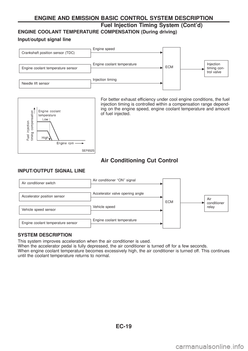
ENGINE COOLANT TEMPERATURE COMPENSATION (During driving)
Input/output signal line
Crankshaft position sensor (TDC)cEngine speed
ECM
c
Injection
timing con-
trol valveEngine coolant temperature sensorcEngine coolant temperature
Needle lift sensor
cInjection timing
For better exhaust efficiency under cool engine conditions, the fuel
injection timing is controlled within a compensation range depend-
ing on the engine speed, engine coolant temperature and amount
of fuel injected.
Air Conditioning Cut Control
INPUT/OUTPUT SIGNAL LINE
Air conditioner switchcAir conditioner ``ON'' signal
ECM
cAir
conditioner
relayAccelerator position sensorcAccelerator valve opening angle
Vehicle speed sensor
cVehicle speed
Engine coolant temperature sensor
cEngine coolant temperature
SYSTEM DESCRIPTION
This system improves acceleration when the air conditioner is used.
When the accelerator pedal is fully depressed, the air conditioner is turned off for a few seconds.
When engine coolant temperature becomes excessively high, the air conditioner is turned off. This continues
until the coolant temperature returns to normal.
SEF652S
ENGINE AND EMISSION BASIC CONTROL SYSTEM DESCRIPTION
Fuel Injection Timing System (Cont'd)
EC-19
Page 188 of 1226
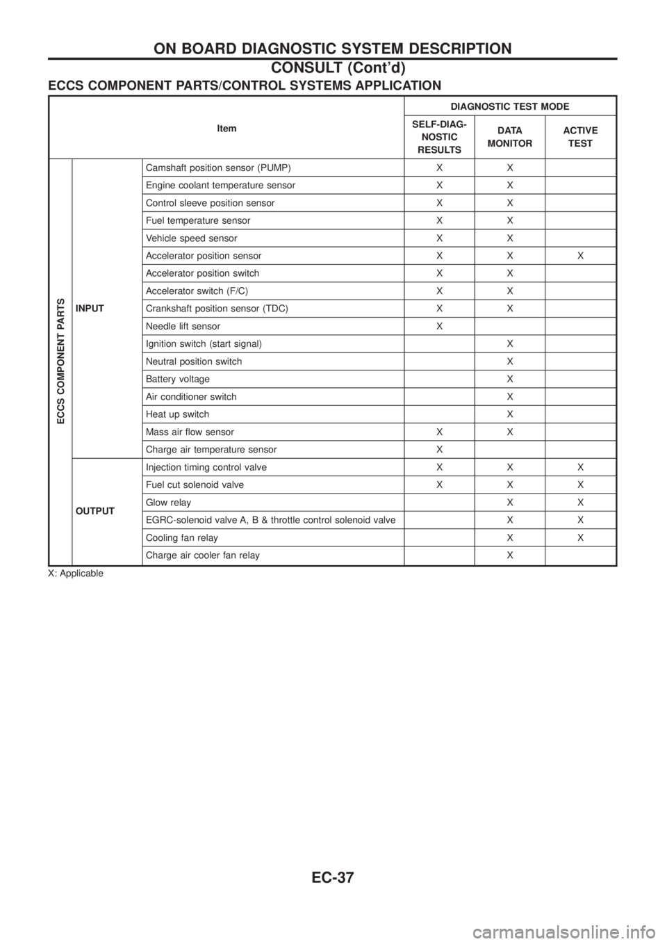
ECCS COMPONENT PARTS/CONTROL SYSTEMS APPLICATION
ItemDIAGNOSTIC TEST MODE
SELF-DIAG-
NOSTIC
RESULTSDATA
MONITORACTIVE
TEST
ECCS COMPONENT PARTS
INPUTCamshaft position sensor (PUMP) X X
Engine coolant temperature sensor X X
Control sleeve position sensor X X
Fuel temperature sensor X X
Vehicle speed sensor X X
Accelerator position sensor X X X
Accelerator position switch X X
Accelerator switch (F/C) X X
Crankshaft position sensor (TDC) X X
Needle lift sensor X
Ignition switch (start signal) X
Neutral position switch X
Battery voltage X
Air conditioner switch X
Heat up switch X
Mass air ¯ow sensor X X
Charge air temperature sensor X
OUTPUTInjection timing control valve X X X
Fuel cut solenoid valve X X X
Glow relayXX
EGRC-solenoid valve A, B & throttle control solenoid valve X X
Cooling fan relay X X
Charge air cooler fan relay X
X: Applicable
ON BOARD DIAGNOSTIC SYSTEM DESCRIPTION
CONSULT (Cont'd)
EC-37
Page 190 of 1226
![NISSAN PATROL 2006 Service Manual Monitored item
[Unit]ECM
input
signalsMain
signalsDescription Remarks
AIR COND SIG
[ON/OFF]
jj
+Indicates [ON/OFF] condition of the air
conditioner switch as determined by the
air conditioner signal.
NISSAN PATROL 2006 Service Manual Monitored item
[Unit]ECM
input
signalsMain
signalsDescription Remarks
AIR COND SIG
[ON/OFF]
jj
+Indicates [ON/OFF] condition of the air
conditioner switch as determined by the
air conditioner signal.](/manual-img/5/57368/w960_57368-189.png)
Monitored item
[Unit]ECM
input
signalsMain
signalsDescription Remarks
AIR COND SIG
[ON/OFF]
jj
+Indicates [ON/OFF] condition of the air
conditioner switch as determined by the
air conditioner signal.
IGN SW
[ON/OFF]
jj+Indicates [ON/OFF] condition from igni-
tion switch signal.
MAS AIR/FL SE [V]
jj+The signal voltage of the mass air ¯ow
sensor is displayed.+When the engine is stopped, a certain
value is indicated.
ACT INJ TIMG [É]
jj
+The actual injection timing angle deter-
mined by the ECM (an approximate
average angle between injection start
and end from TDC) is displayed.
INJ TIMG C/V [%]+Indicates the duty ratio of fuel injection
timing control valve.
DECELER F/CUT
[ON/OFF]
j
+Indicates [ON/OFF] condition from decel-
eration fuel cut signal.+When the accelerator pedal is released
quickly with engine speed at 3,000 rpm
or more, ``ON'' is displayed.
FUEL CUT S/V
[ON/OFF]
j
+The control condition of the fuel cut sole-
noid valve (determined by ECM accord-
ing to the input signal) is indicted.
+OFF ... Fuel cut solenoid valve is not
operating.
ON ... Fuel cut solenoid valve is operat-
ing.+When the fuel cut solenoid valve is not
operating, fuel is not supplied to injection
nozzles.
GLOW RLY [ON/OFF]
j
+The glow relay control condition (deter-
mined by ECM according to the input
signal) is displayed.
COOLING FAN
[LOW/HI/OFF]
j
+Indicates the control condition of the
cooling fans (determined by ECM
according to the input signal).
+LOW ... Operates at low speed.
HI ... Operates at high speed.
OFF ... Stopped.
I/C FAN RLY
[ON/OFF]
j
+Indicates the control condition of the
charge air cooler fan (determined by
ECM according to the input signals).
EGRC SOL/V A
[ON/OFF]+The control condition of the EGRC-sole-
noid valve A (determined by ECM
according to the input signal) is indi-
cated.
+OFF ... EGRC-solenoid valve A is not
operating.
ON ... EGRC-solenoid valve A is operat-
ing.
EGRC SOL/V B
[ON/OFF]+The control condition of the EGRC-sole-
noid valve B (determined by ECM
according to the input signal) is indi-
cated.
+OFF ... EGRC-solenoid valve B is not
operating.
ON ... EGRC-solenoid valve B is operat-
ing.
THROT RLY
[ON/OFF]+The control condition of the throttle con-
trol solenoid valve (determined by ECM
according to the input signal) is indi-
cated.
+OFF ... Throttle control solenoid valve is
not operating.
ON ... Throttle control solenoid valve is
operating.
ON BOARD DIAGNOSTIC SYSTEM DESCRIPTION
CONSULT (Cont'd)
EC-39