2006 NISSAN PATROL radiator
[x] Cancel search: radiatorPage 734 of 1226
Precautions
+When installing rubber parts, ®nal tightening must be car-
ried out under unladen condition* with tires on ground.
* Fuel, radiator coolant and engine oil full. Spare tire, jack,
hand tools and mats in designated positions.
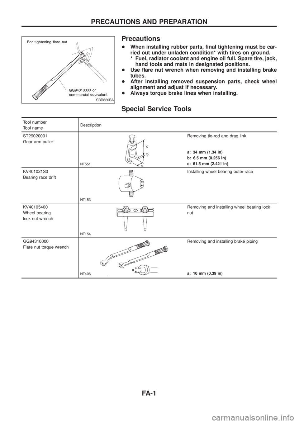
+Use ¯are nut wrench when removing and installing brake
tubes.
+After installing removed suspension parts, check wheel
alignment and adjust if necessary.
+Always torque brake lines when installing.
Special Service Tools
Tool number
Tool nameDescription
ST29020001
Gear arm puller
NT551
Removing tie-rod and drag link
a: 34 mm (1.34 in)
b: 6.5 mm (0.256 in)
c: 61.5 mm (2.421 in)
KV401021S0
Bearing race drift
NT153
Installing wheel bearing outer race
KV40105400
Wheel bearing
lock nut wrench
NT154
Removing and installing wheel bearing lock
nut
GG94310000
Flare nut torque wrench
NT406
Removing and installing brake piping
a: 10 mm (0.39 in)
SBR820BA
PRECAUTIONS AND PREPARATION
FA-1
Page 741 of 1226
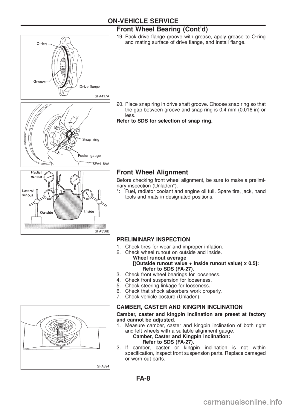
19. Pack drive ¯ange groove with grease, apply grease to O-ring
and mating surface of drive ¯ange, and install ¯ange.
20. Place snap ring in drive shaft groove. Choose snap ring so that
the gap between groove and snap ring is 0.4 mm (0.016 in) or
less.
Refer to SDS for selection of snap ring.
Front Wheel Alignment
Before checking front wheel alignment, be sure to make a prelimi-
nary inspection (Unladen*).
*: Fuel, radiator coolant and engine oil full. Spare tire, jack, hand
tools and mats in designated positions.
PRELIMINARY INSPECTION
1. Check tires for wear and improper in¯ation.
2. Check wheel runout on outside and inside.
Wheel runout average
[(Outside runout value + Inside runout value) x 0.5]:
Refer to SDS (FA-27).
3. Check front wheel bearings for looseness.
4. Check front suspension for looseness.
5. Check steering linkage for looseness.
6. Check that shock absorbers work properly.
7. Check vehicle posture (Unladen).
CAMBER, CASTER AND KINGPIN INCLINATION
Camber, caster and kingpin inclination are preset at factory
and cannot be adjusted.
1. Measure camber, caster and kingpin inclination of both right
and left wheels with a suitable alignment gauge.
Camber, Caster and Kingpin inclination:
Refer to SDS (FA-27).
2. If camber, caster or kingpin inclination is not within
speci®cation, inspect front suspension parts. Replace damaged
or worn out parts.
SFA417A
SFA418AA
SFA356B
SFA894
ON-VEHICLE SERVICE
Front Wheel Bearing (Cont'd)
FA-8
Page 760 of 1226
General Speci®cations
Suspension typeRigid axle, leading arm and panhard rod with
coil spring
Strut type Double-acting hydraulic
Stabilizer bar Standard equipment
Inspection and Adjustment
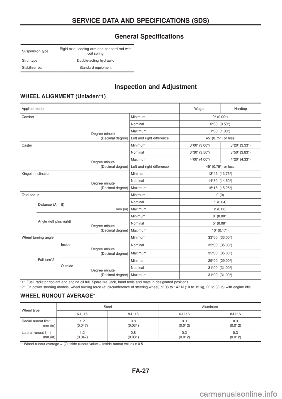
WHEEL ALIGNMENT (Unladen*1)
Applied modelWagon Hardtop
Camber Minimum 0É (0.00É)
Degree minute
(Decimal degree)Nominal 0É30¢(0.50É)
Maximum 1É00¢(1.00É)
Left and right difference 45¢(0.75É) or less
Caster Minimum 3É00¢(3.00É) 3É20¢(3.33É)
Degree minute
(Decimal degree)Nominal 3É30¢(3.50É) 3É50¢(3.83É)
Maximum 4É00¢(4.00É) 4É20¢(4.33É)
Left and right difference 45¢(0.75É) or less
Kingpin inclination Minimum 13É45¢(13.75É)
Degree minute
(Decimal degree)Nominal 14É30¢(14.50É)
Maximum 15É15¢(15.25É)
Total toe-in Minimum 0 (0)
Distance (A þ B)
mm (in)Nominal 1 (0.04)
Maximum 2 (0.08)
Angle (left plus right)
Degree minute
(Decimal degree)Minimum 0¢(0.00É)
Nominal 5¢(0.08É)
Maximum 10¢(0.17É)
Wheel turning angle Minimum 33É00¢(33.00É)
Full turn*2Inside
Degree minute
(Decimal degree)Nominal 35É00¢(35.00É)
Maximum 35É00¢(35.00É)
Outside
Degree minute
(Decimal degree)Minimum 29É00¢(29.00É)
Nominal 31É00¢(31.00É)
Maximum 31É00¢(31.00É)
*1: Fuel, radiator coolant and engine oil full. Spare tire, jack, hand tools and mats in designated positions.
*2: On power steering models, wheel turning force (at circumference of steering wheel) of 98 to 147 N (10 to 15 kg, 22 to 33 lb) with engine idle.
WHEEL RUNOUT AVERAGE*
Wheel typeSteel Aluminum
6JJ-16 8JJ-16 6JJ-16 8JJ-16
Radial runout limit
mm (in)1.2
(0.047)0.8
(0.031)0.3
(0.012)0.3
(0.012)
Lateral runout limit
mm (in)1.2
(0.047)0.8
(0.031)0.3
(0.012)0.3
(0.012)
*: Wheel runout average = (Outside runout value + Inside runout value) x 0.5
SERVICE DATA AND SPECIFICATIONS (SDS)
FA-27
Page 775 of 1226

General Precautions
+Do not operate the engine for an extended period of time with-
out proper exhaust ventilation.
Keep the work area well ventilated and free of any in¯ammable
materials. Special care should be taken when handling any
in¯ammable or poisonous materials, such as gasoline, refriger-
ant gas, etc. When working in a pit or other enclosed area, be
sure to properly ventilate the area before working with hazard-
ous materials.
Do not smoke while working on the vehicle.
+Before jacking up the vehicle, apply wheel chocks or other tire
blocks to the wheels to prevent the vehicle from moving. After
jacking up the vehicle, support the vehicle weight with safety
stands at the points designated for proper lifting before work-
ing on the vehicle.
These operations should be done on a level surface.
+When removing a heavy component such as the engine or
transaxle/transmission, be careful not to lose your balance and
drop it. Also, do not allow it to strike adjacent parts, especially
the brake tubes and master cylinder.
+Before starting repairs which do not require battery power:
Turn off ignition switch.
Disconnect the negative battery terminal.
+To prevent serious burns:
Avoid contact with hot metal parts.
Do not remove the radiator cap when the engine is hot.
+Before servicing the vehicle:
Protect fenders, upholstery and carpeting with appropriate cov-
ers.
Take caution that keys, buckles or buttons do not scratch paint.
SGI285
SGI231
SEF289H
SGI233
SGI234
PRECAUTIONS
GI-2
Page 953 of 1226
ROOM/L - Wiring diagram ..............................EL-95
Radiator ..........................................................LC-14
Radio - See Audio.........................................EL-168
Rear axle (disc brake type) ..............................RA-6
Rear bumper .....................................................BT-6
Rear case (Transfer) .......................................TF-10
Rear combination lamp removal and
installation ...................................................BT-26
Rear cover packing replacement diff..............PD-11
Rear disc brake ..............................................BR-24
Rear door ........................................................BT-10
Rear fog lamp .................................................EL-80
Rear heater - Wiring diagram ........................HA-14
Rear seat belt ...................................................RS-5
Rear seat ........................................................BT-35
Rear side window ...........................................BT-44
Rear suspension ............................................RA-12
Rear washer..................................................EL-145
Rear window defogger ..................................EL-158
Rear window ...................................................BT-42
Rear wiper.....................................................EL-145
Refrigerant connection precaution ...................HA-2
Refrigerant discharging evacuating
charging ....................................................HA-113
Refrigerant general precaution.........................HA-2
Refrigerant lines ...........................................HA-117
Refrigeration cycle ..........................................HA-11
Release bearing (clutch) .................................CL-11
Removal and installation (Transfer) ..................TF-8
Reverse idler shaft (M/T) ...............................MT-10
Reverse lamp switch (M/T) - See
Back-up lamp switch (M/T)...........................MT-4
Reverse main gear (M/T) ...............................MT-10
Ring gear diff. inspection ...............................PD-19
Road wheel size ..............................................GI-38
Roof trim .........................................................BT-20
Room lamp - See Interior lamp ......................EL-93
Rotor disc (front) .............................................FA-14
S
S/LOCK - Wiring diagram .............................EL-215
S/SIG - Wiring diagram ................................EC-162
SAE J1930 terminology list .............................GI-43
SEAT - Wiring diagram .................................EL-190
SMJ (super multiple junction) .......................EL-317
SROOF - Wiring diagram .............................EL-186
SRS - See Supplemental Restraint
System ..........................................................RS-8
SRS Trouble diagnoses .................................RS-22
STAB - Wiring diagram ..................................RA-18
START - Wiring diagram .................................EL-45
Screw jack .......................................................GI-39
Seal - See Exterior .........................................BT-26
Seat belt inspection .......................................MA-27
Seat belt pre-tensioner disposal ....................RS-17
Seat belt pre-tensioner ...................................RS-12
Seat belt, front ..................................................RS-2
Seat belt, rear...................................................RS-5Seat, front .......................................................BT-32
Seat, rear ........................................................BT-35
Seat, second (2nd) .........................................BT-35
Seat, third (3rd) ...............................................BT-37
Second (2nd) seat ..........................................BT-35
Self-diagnostic results ....................................EC-31
Shift control (Transfer) ....................................TF-12
Shift control components (M/T) ......................MT-12
Shift fork (M/T) ...............................................MT-12
Shift lever .......................................................MT-12
Shock absorber (front) ....................................FA-25
Shock absorber (rear) ....................................RA-14
Side bearing preload (front ®nal drive
4WD)...........................................................PD-27
Side bearing preload diff. ...............................PD-27
Side trim ..........................................................BT-14
Side window - See Rear side window ............BT-44
Speedometer.................................................EL-102
Spiral cable.....................................................RS-13
Stabilizer bar (front) ........................................FA-25
Stabilizer bar (rear) ........................................RA-15
Stabilizer release device - Wiring
diagram .......................................................RA-18
Stabilizer release device ................................RA-16
Standardized relay ............................................EL-3
Start signal ...................................................EC-162
Starter .............................................................EL-51
Starting system ...............................................EL-45
Steering gear and linkage inspection ............MA-26
Steering linkage ..............................................ST-19
Steering switch................................................EL-59
Steering wheel and column ..............................ST-8
Steering wheel play ..........................................ST-4
Steering wheel turning force .............................ST-6
Striking rod (M/T) ...........................................MT-12
Sub-gear (M/T) ...............................................MT-10
Sunload sensor ............................................HA-107
Sunroof, electric ............................................EL-186
Sunroof............................................................BT-39
Super lock .....................................................EL-211
Supplemental Restraint System .......................RS-8
Supplemental restraint system - Wiring
diagram .......................................................RS-27
Symbols and abbreviations ...............................GI-7
Synchronizer (M/T) .........................................MT-10
T
TCV - Wiring diagram ..................................EC-100
Tachometer ...................................................EL-102
Thermometer .................................................EL-116
Thermostat ......................................................LC-12
Third (3rd) seat ...............................................BT-37
Three way catalyst precautions.........................GI-4
Throttle control solenoid valve .....................EC-155
Throttle control solenoid valve .....................EC-161
Throwout bearing - See Clutch release
bearing ........................................................CL-11
Thrust washer selection diff. ..........................PD-27
ALPHABETICAL INDEX
IDX-6
Page 955 of 1226
ENGINE LUBRICATION &
COOLING SYSTEMS
SECTION
LC
CONTENTS
PRECAUTIONS AND PREPARATION............................1
Liquid Gasket Application Procedure ..........................1
Special Service Tools ..................................................2
ENGINE LUBRICATION SYSTEM..................................3
Lubrication Circuit ........................................................3
Oil Pressure Check......................................................3
Oil Pump ......................................................................4
Oil Cooler .....................................................................7
Oil Jet...........................................................................7
Turbocharger ...............................................................8
ENGINE COOLING SYSTEM..........................................9
Cooling Circuit .............................................................9System Check..............................................................9
Water Pump ...............................................................10
Thermostat .................................................................12
Radiator .....................................................................14
Re®lling Engine Coolant ............................................14
Cooling Fan (Crankshaft driven) ...............................15
Cooling Fan (Motor driven)........................................15
Radiator (Aluminum type) ..........................................16
Overheating Cause Analysis .....................................20
SERVICE DATA AND SPECIFICATIONS (SDS)..........21
Engine Lubrication System ........................................21
Engine Cooling System .............................................21
LC
Page 957 of 1226
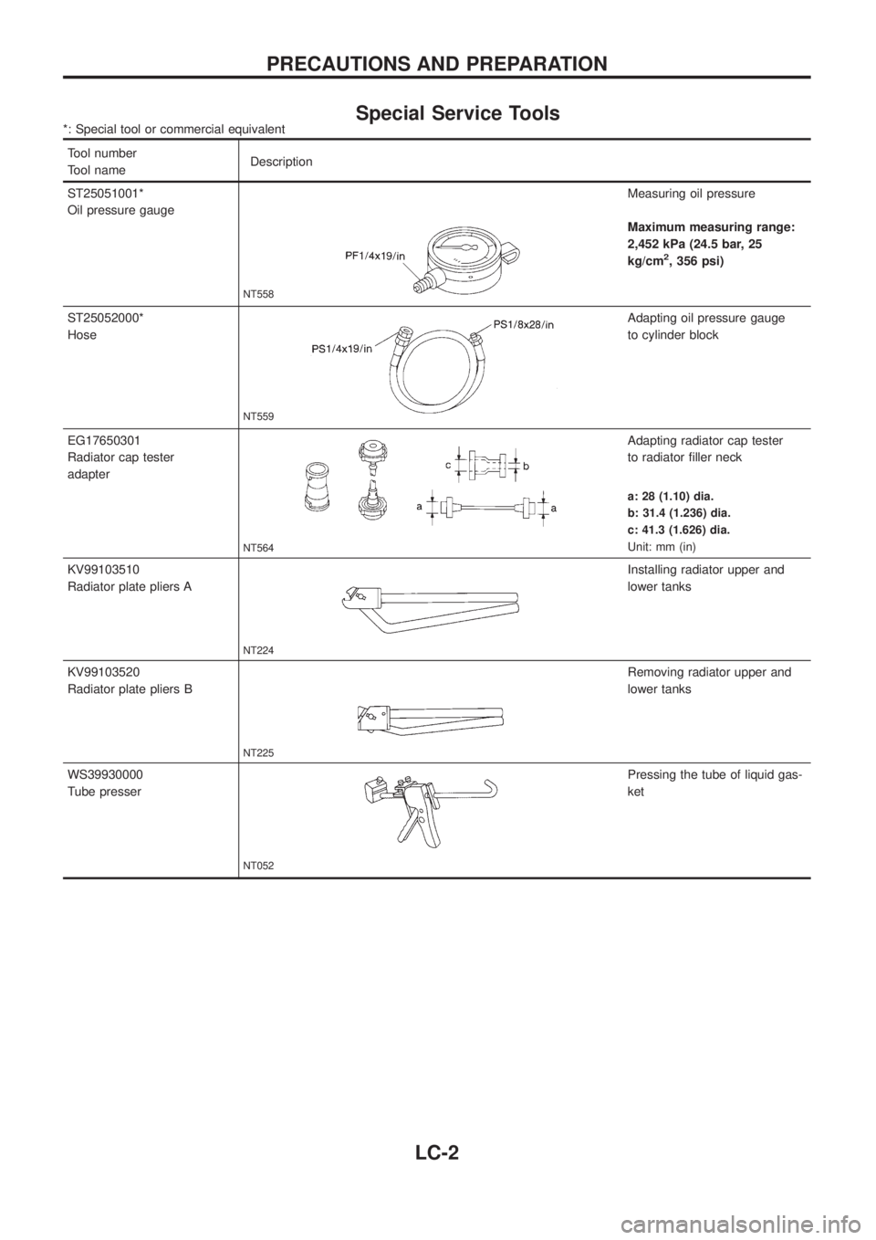
Special Service Tools*: Special tool or commercial equivalent
Tool number
Tool nameDescription
ST25051001*
Oil pressure gauge
NT558
Measuring oil pressure
Maximum measuring range:
2,452 kPa (24.5 bar, 25
kg/cm
2, 356 psi)
ST25052000*
Hose
NT559
Adapting oil pressure gauge
to cylinder block
EG17650301
Radiator cap tester
adapter
NT564
Adapting radiator cap tester
to radiator ®ller neck
a: 28 (1.10) dia.
b: 31.4 (1.236) dia.
c: 41.3 (1.626) dia.
Unit: mm (in)
KV99103510
Radiator plate pliers A
NT224
Installing radiator upper and
lower tanks
KV99103520
Radiator plate pliers B
NT225
Removing radiator upper and
lower tanks
WS39930000
Tube presser
NT052
Pressing the tube of liquid gas-
ket
PRECAUTIONS AND PREPARATION
LC-2
Page 959 of 1226
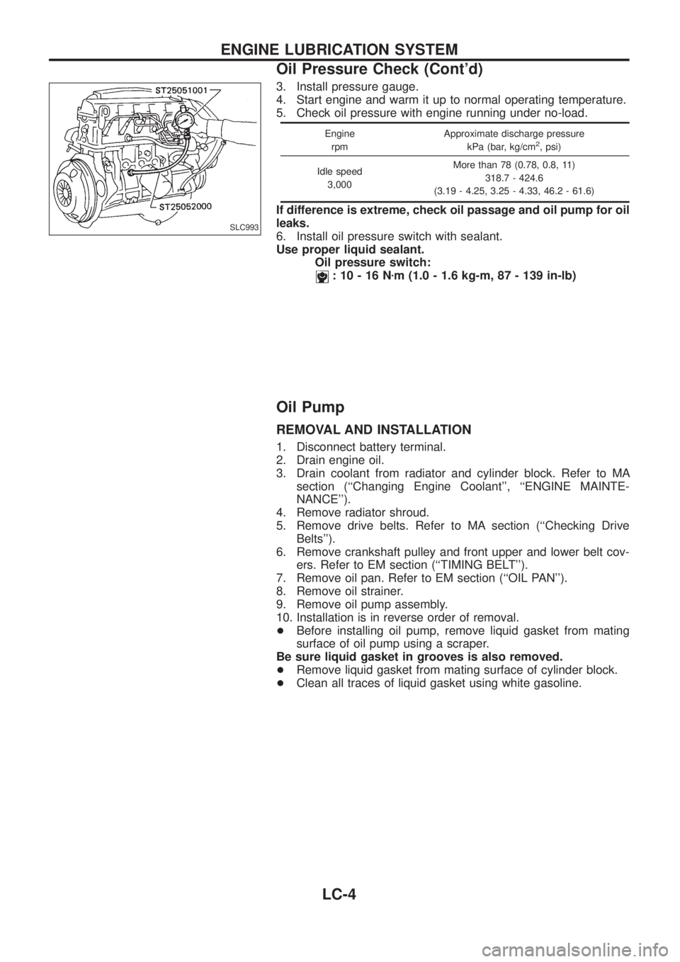
3. Install pressure gauge.
4. Start engine and warm it up to normal operating temperature.
5. Check oil pressure with engine running under no-load.
Engine
rpmApproximate discharge pressure
kPa (bar, kg/cm2, psi)
Idle speed
3,000More than 78 (0.78, 0.8, 11)
318.7 - 424.6
(3.19 - 4.25, 3.25 - 4.33, 46.2 - 61.6)
If difference is extreme, check oil passage and oil pump for oil
leaks.
6. Install oil pressure switch with sealant.
Use proper liquid sealant.
Oil pressure switch:
:10-16Nzm (1.0 - 1.6 kg-m, 87 - 139 in-lb)
Oil Pump
REMOVAL AND INSTALLATION
1. Disconnect battery terminal.
2. Drain engine oil.
3. Drain coolant from radiator and cylinder block. Refer to MA
section (``Changing Engine Coolant'', ``ENGINE MAINTE-
NANCE'').
4. Remove radiator shroud.
5. Remove drive belts. Refer to MA section (``Checking Drive
Belts'').
6. Remove crankshaft pulley and front upper and lower belt cov-
ers. Refer to EM section (``TIMING BELT'').
7. Remove oil pan. Refer to EM section (``OIL PAN'').
8. Remove oil strainer.
9. Remove oil pump assembly.
10. Installation is in reverse order of removal.
+Before installing oil pump, remove liquid gasket from mating
surface of oil pump using a scraper.
Be sure liquid gasket in grooves is also removed.
+Remove liquid gasket from mating surface of cylinder block.
+Clean all traces of liquid gasket using white gasoline.
SLC993
ENGINE LUBRICATION SYSTEM
Oil Pressure Check (Cont'd)
LC-4