2006 NISSAN PATROL air bleeding
[x] Cancel search: air bleedingPage 28 of 1226
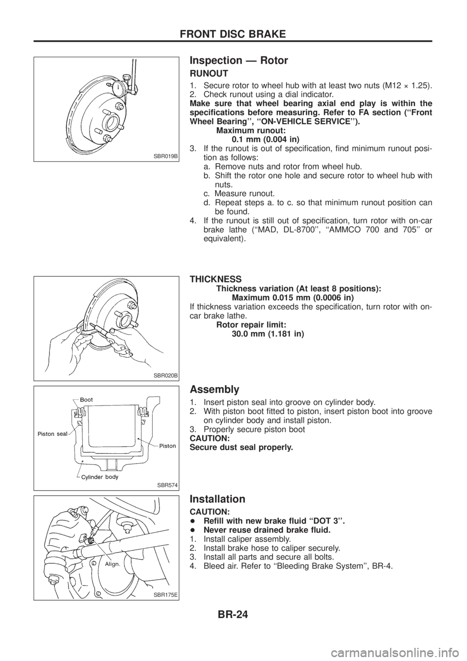
Inspection Ð Rotor
RUNOUT
1. Secure rotor to wheel hub with at least two nuts (M12 ý 1.25).
2. Check runout using a dial indicator.
Make sure that wheel bearing axial end play is within the
speci®cations before measuring. Refer to FA section (``Front
Wheel Bearing'', ``ON-VEHICLE SERVICE'').Maximum runout:0.1 mm (0.004 in)
3. If the runout is out of speci®cation, ®nd minimum runout posi- tion as follows:
a. Remove nuts and rotor from wheel hub.
b. Shift the rotor one hole and secure rotor to wheel hub withnuts.
c. Measure runout.
d. Repeat steps a. to c. so that minimum runout position can be found.
4. If the runout is still out of speci®cation, turn rotor with on-car brake lathe (``MAD, DL-8700'', ``AMMCO 700 and 705'' or
equivalent).
THICKNESS
Thickness variation (At least 8 positions): Maximum 0.015 mm (0.0006 in)
If thickness variation exceeds the speci®cation, turn rotor with on-
car brake lathe. Rotor repair limit:30.0 mm (1.181 in)
Assembly
1. Insert piston seal into groove on cylinder body.
2. With piston boot ®tted to piston, insert piston boot into grooveon cylinder body and install piston.
3. Properly secure piston boot
CAUTION:
Secure dust seal properly.
Installation
CAUTION:
+ Re®ll with new brake ¯uid ``DOT 3''.
+ Never reuse drained brake ¯uid.
1. Install caliper assembly.
2. Install brake hose to caliper securely.
3. Install all parts and secure all bolts.
4. Bleed air. Refer to ``Bleeding Brake System'', BR-4.
SBR019B
SBR020B
SBR574
SBR175E
FRONT DISC BRAKE
BR-24
Page 32 of 1226
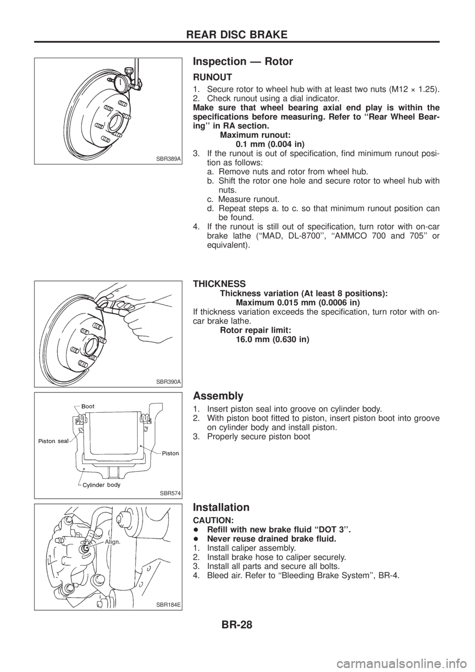
Inspection Ð Rotor
RUNOUT
1. Secure rotor to wheel hub with at least two nuts (M12 ý 1.25).
2. Check runout using a dial indicator.
Make sure that wheel bearing axial end play is within the
speci®cations before measuring. Refer to ``Rear Wheel Bear-
ing'' in RA section.Maximum runout:0.1 mm (0.004 in)
3. If the runout is out of speci®cation, ®nd minimum runout posi- tion as follows:
a. Remove nuts and rotor from wheel hub.
b. Shift the rotor one hole and secure rotor to wheel hub withnuts.
c. Measure runout.
d. Repeat steps a. to c. so that minimum runout position can be found.
4. If the runout is still out of speci®cation, turn rotor with on-car brake lathe (``MAD, DL-8700'', ``AMMCO 700 and 705'' or
equivalent).
THICKNESS
Thickness variation (At least 8 positions): Maximum 0.015 mm (0.0006 in)
If thickness variation exceeds the speci®cation, turn rotor with on-
car brake lathe. Rotor repair limit:16.0 mm (0.630 in)
Assembly
1. Insert piston seal into groove on cylinder body.
2. With piston boot ®tted to piston, insert piston boot into grooveon cylinder body and install piston.
3. Properly secure piston boot
Installation
CAUTION:
+ Re®ll with new brake ¯uid ``DOT 3''.
+ Never reuse drained brake ¯uid.
1. Install caliper assembly.
2. Install brake hose to caliper securely.
3. Install all parts and secure all bolts.
4. Bleed air. Refer to ``Bleeding Brake System'', BR-4.
SBR389A
SBR390A
SBR574
SBR184E
REAR DISC BRAKE
BR-28
Page 42 of 1226
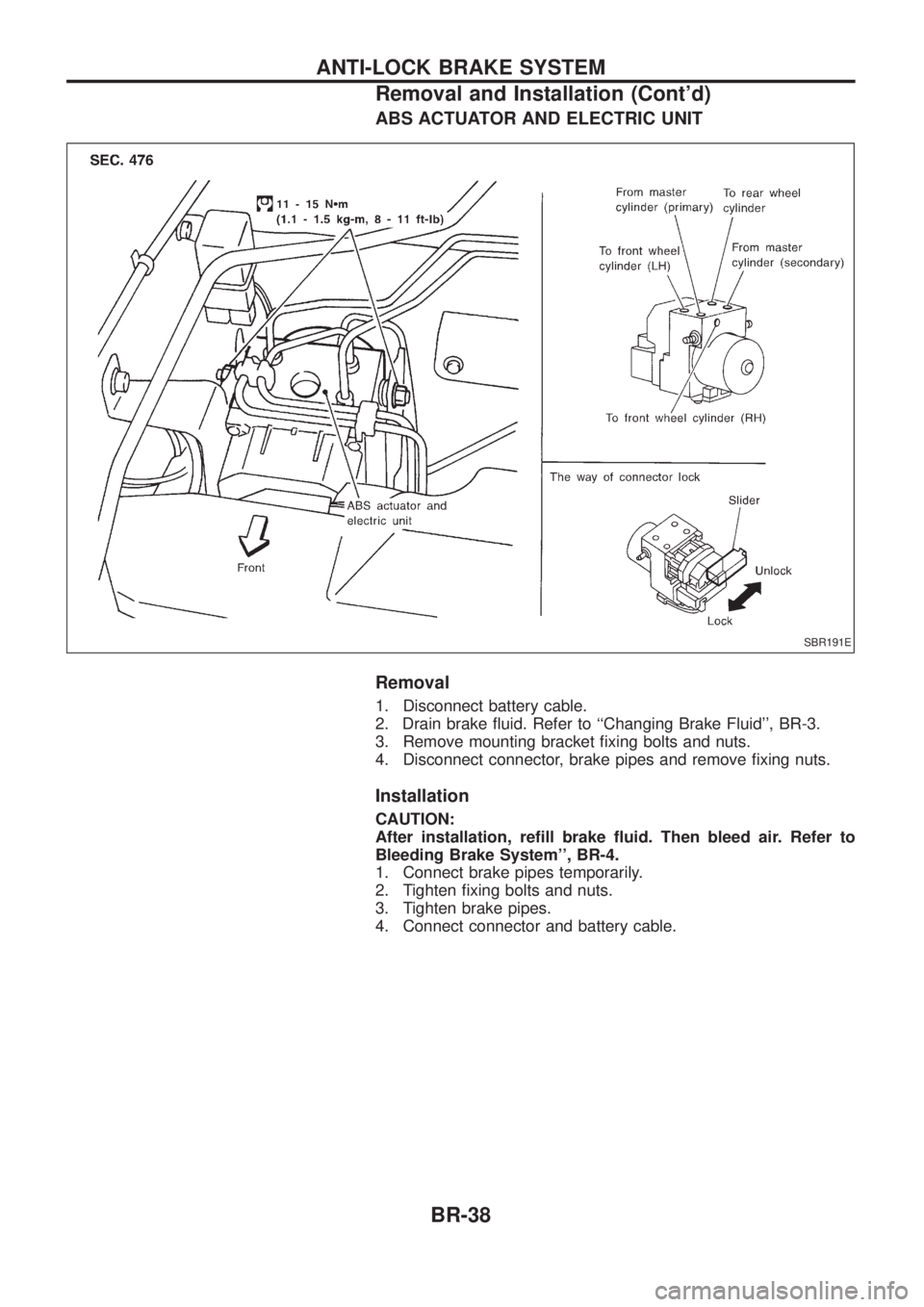
ABS ACTUATOR AND ELECTRIC UNIT
Removal
1. Disconnect battery cable.
2. Drain brake ¯uid. Refer to ``Changing Brake Fluid'', BR-3.
3. Remove mounting bracket ®xing bolts and nuts.
4. Disconnect connector, brake pipes and remove ®xing nuts.
Installation
CAUTION:
After installation, re®ll brake ¯uid. Then bleed air. Refer to
Bleeding Brake System'', BR-4.
1. Connect brake pipes temporarily.
2. Tighten ®xing bolts and nuts.
3. Tighten brake pipes.
4. Connect connector and battery cable.
SBR191E
ANTI-LOCK BRAKE SYSTEM
Removal and Installation (Cont'd)BR-38
Page 133 of 1226
CLUTCH
SECTION
CL
CONTENTS
PRECAUTIONS AND PREPARATION............................1
Precautions ..................................................................1
Special Service Tools ..................................................1
Commercial Service Tools ...........................................2
NOISE, VIBRATION AND HARSHNESS (NVH)
TROUBLESHOOTING.....................................................3
NVH Troubleshooting Chart.........................................3
CLUTCH SYSTEM...........................................................4
INSPECTION AND ADJUSTMENT.................................5
Adjusting Clutch Pedal ................................................5
Air Bleeding Procedure................................................6HYDRAULIC CLUTCH CONTROL.................................7
Clutch Master Cylinder ................................................7
Clutch Operating Cylinder ...........................................8
Clutch Booster .............................................................9
CLUTCH RELEASE MECHANISM............................... 11
CLUTCH DISC AND CLUTCH COVER........................13
Clutch Disc.................................................................13
Clutch Cover and Flywheel .......................................14
SERVICE DATA AND SPECIFICATIONS (SDS)..........16
General Speci®cations ...............................................16
Inspection and Adjustment ........................................16
CL
Page 139 of 1226
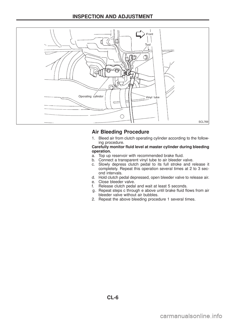
Air Bleeding Procedure
1. Bleed air from clutch operating cylinder according to the follow-
ing procedure.
Carefully monitor ¯uid level at master cylinder during bleeding
operation.
a. Top up reservoir with recommended brake ¯uid.
b. Connect a transparent vinyl tube to air bleeder valve.
c. Slowly depress clutch pedal to its full stroke and release it
completely. Repeat this operation several times at 2 to 3 sec-
ond intervals.
d. Hold clutch pedal depressed, open bleeder valve to release air.
e. Close bleeder valve.
f. Release clutch pedal and wait at least 5 seconds.
g . Repeat steps c through e above until brake ¯uid ¯ows from air
bleeder valve without air bubbles.
2. Repeat the above bleeding procedure 1 several times.
SCL769
INSPECTION AND ADJUSTMENT
CL-6
Page 949 of 1226
A
A/C HFC134a (R134a) system service
procedure ..................................................HA-112
A/C HFC134a system service equip-
ment precaution ............................................HA-9
A/C air ¯ow .....................................................HA-13
A/C component layout ....................................HA-12
A/C compressor precaution..............................HA-6
A/C compressor special service tool ...........HA-6, 7
A/C control linkage adjustment (auto
A/C).............................................................HA-77
A/C control operation (manual A/C) ...............HA-16
A/C harness layout (manual A/C) ..................HA-17
A/C lubricant (R134a) ...................................HA-114
A/C relay.........................................................HA-97
A/C self-diagnoses (auto A/C)........................HA-63
A/CCUT - Wiring diagram ............................EC-186
A/T control ....................................................EC-174
ABS sensor rotor ............................................FA-15
ACC/SW - Wiring diagram ...........................EC-105
ACL/SW - Wiring diagram ............................EC-164
ADJRES - Wiring diagram .............................EC-91
APS - Wiring diagram ..................................EC-138
AT/C - Wiring diagram..................................EC-174
AUDIO - Wiring diagram ...............................EL-168
Accelerator position sensor ..........................EC-138
Accelerator position switch...........................EC-164
Accelerator switch (F/C) ...............................EC-105
Adjustment resistor.........................................EC-91
Air bag disposal..............................................RS-17
Air bag ..............................................................RS-8
Air bleeding (hydraulic clutch) ..........................CL-6
Air bleeding for brake system ..........................BR-4
Air cleaner ®lter replacement .........................MA-18
Air conditioner cut control ..............................EC-19
Air ¯ow meter - See Mass air ¯ow
sensor .........................................................EC-73
Air mix door control linkage
adjustment ................................................HA-81
Alternator.........................................................EL-56
Antenna - See Power antenna .....................EL-181
Audio and A/C control removal and
installation - See Instrument panel .............BT-11
Audio .............................................................EL-168
Auto lock free running hub .............................FA-13
Automatic ampli®er .........................................HA-61
Axle housing (rear) ...........................................RA-9
B
BACK/L - Wiring diagram................................EL-78
Back door opener - See Back door ..................BT-6
Back door trim.................................................BT-24
Back door window...........................................BT-45
Back door ..........................................................BT-6Back-up lamp switch (M/T) ..............................MT-4
Back-up lamp ..................................................EL-78
Battery .............................................................EL-37
Baulk ring (M/T)..............................................MT-10
Body alignment ...............................................BT-49
Body mounting ................................................BT-48
Brake booster .................................................BR-15
Brake ¯uid change ...........................................BR-3
Brake ¯uid level and line check .......................BR-3
Brake ¯uid level .............................................MA-23
Brake hydraulic line ..........................................BR-5
Brake inspection ............................................MA-24
Brake master cylinder ....................................BR-12
Brake pedal ....................................................BR-10
Bulb speci®cations ........................................EL-314
Bumper, front ................................................... BT-4
Bumper, rear .....................................................BT-6
C
CD/CHG - Wiring diagram ............................EL-176
CHIME - Wiring diagram...............................EL-136
CIGAR - Wiring diagram ...............................EL-156
CKPS - Wiring diagram ................................EC-143
CLOCK - Wiring diagram ..............................EL-157
CMPS - Wiring diagram .................................EC-68
COMPAS - Wiring diagram ...........................EL-117
CONSULT for ECCS ......................................EC-36
CONSULT general information ........................GI-33
COOL/F - Wiring diagram ............................EC-112
CSPS - Wiring diagram ..................................EC-86
Cab body.........................................................BT-47
Camshaft inspection ......................................EM-36
Camshaft position sensor (PUMP).................EC-68
Center case (Transfer) ....................................TF-10
Charge air cooler fan control .......................EC-177
Charge air temperature sensor ....................EC-121
Chassis and body maintenance ....................MA-20
Cigarette lighter.............................................EL-156
Circuit breaker.................................................EL-14
Clock .............................................................EL-157
Clutch booster...................................................CL-9
Clutch cover ....................................................CL-14
Clutch damper ..................................................CL-7
Clutch disc ......................................................CL-13
Clutch ¯uid level.............................................MA-20
Clutch master cylinder ......................................CL-7
Clutch operating cylinder ..................................CL-8
Clutch pedal ......................................................CL-5
Clutch release bearing ....................................CL-11
Clutch release mechanism .............................CL-11
Clutch withdrawal lever ...................................CL-11
Coil spring (front) ............................................FA-25
Coil spring (rear) ............................................RA-14
Collision diagnosis..........................................RS-45
Combination meter removal and instal-
lation - See Instrument panel ......................BT-11
ALPHABETICAL INDEX
IDX-2
Page 952 of 1226
M
M/T major overhaul ..........................................MT-9
M/T removal and installation ............................MT-5
MAFS - Wiring diagram..................................EC-73
MAIN - Wiring diagram...................................EC-62
METER - Wiring diagram..............................EL-104
MIL & Data link connectors circuit ...............EC-187
MIL/DL - Wiring diagram ..............................EC-187
MIRROR - Wiring diagram............................EL-188
Main drive gear (M/T).....................................MT-10
Main gear (Transfer) .......................................TF-11
Mainshaft (M/T) ..............................................MT-10
Mainshaft (Transfer) ........................................TF-11
Maintenance (engine) ....................................MA-12
Major overhaul (Transfer) ...............................TF-10
Malfunction indicator lamp (MIL) ....................EC-31
Manifold tightening torque (intake &
exhaust)......................................................MA-12
Manual lock free running hub .........................FA-11
Manual transmission number ..........................GI-37
Mass air ¯ow sensor (MAFS).........................EC-73
Master cylinder (brake) ..................................BR-12
Meter .............................................................EL-102
Mirror, door......................................................BT-46
Mirror, outside .................................................BT-46
Mode door control linkage adjustment ...........HA-77
Model variation ................................................GI-35
Molding - See Exterior ....................................BT-26
Multiport fuel injection precautions ....................GI-3
N
NATS (Nissan Anti-theft System)..................EL-240
NATS - Wiring diagram .................................EL-241
NLS - Wiring diagram...................................EC-125
NVH Troubleshooting (PD)...............................PD-4
NVH troubleshooting (BR)................................BR-2
NVH troubleshooting (EM) ...............................EM-6
NVH troubleshooting (FA) .................................FA-3
NVH troubleshooting (MT) ...............................MT-3
NVH troubleshooting (RA)................................RA-3
NVH troubleshooting (RA)................................RA-3
NVH troubleshooting (ST).................................ST-3
NVH troubleshooting (Transfer) ........................TF-3
NVH troubleshooting CL ...................................CL-3
Needle lift sensor .........................................EC-125
Neutral position switch (M/T) ...........................MT-4
Neutral position switch .................................EC-169
O
Oil change (capacity) .......................................MA-9
Oil cooler (engine) ............................................LC-7
Oil jet.................................................................LC-7
Oil pan (engine) .............................................EM-13Oil pressure (engine) ........................................LC-3
Oil pump (engine) .............................................LC-4
Oil seal replacement (engine)........................EM-20
Oil seal replacement (front ®nal drive
4WD)...........................................................PD-10
Oil seal replacement (front of ®nal
drive) ...........................................................PD-10
Operating cylinder (clutch)................................CL-8
Outside mirror .................................................BT-46
P
P/ANT - Wiring diagram................................EL-181
PCV (positive crankcase ventilation) .............EC-21
PNP/SW - Wiring diagram ...........................EC-169
POWER - Wiring diagram.................................EL-6
Park/Neutral position switch .........................EC-169
Periodic maintenance (for Europe) ..................MA-4
Pinion bearing preload diff. ............................PD-27
Pinion gear height diff. ...................................PD-27
Piston assembly .............................................EM-46
Piston pin inspection ......................................EM-46
Piston ring inspection.....................................EM-47
Piston to bore clearance ................................EM-48
Power antenna ..............................................EL-181
Power door lock ............................................EL-204
Power door lock ............................................EL-211
Power door mirror .........................................EL-188
Power seat ....................................................EL-190
Power steering ¯uid level..................................ST-5
Power steering gear........................................ST-12
Power steering hydraulic pressure ...................ST-6
Power steering oil pump .................................ST-15
Power steering system bleeding.......................ST-6
Power supply routing ........................................EL-5
Power window ...............................................EL-196
Pre-delivery inspection.....................................MA-2
Precautions (General) .......................................GI-2
Pressure plate - See Clutch cover .................CL-14
Priming pump .................................................EC-46
Propeller shaft greasing .................................MA-21
Propeller shaft inspection ..............................MA-21
Propeller shaft on vehicle service ....................PD-6
Propeller shaft vibration ...................................PD-6
Propeller shaft ..................................................PD-5
Q
Quick-glow system check.............................EC-153
Quick-glow system .......................................EC-150
R
R/FOG - Wiring diagram .................................EL-80
R/HEAT - Wiring diagram ...............................HA-14
ALPHABETICAL INDEX
IDX-5
Page 994 of 1226
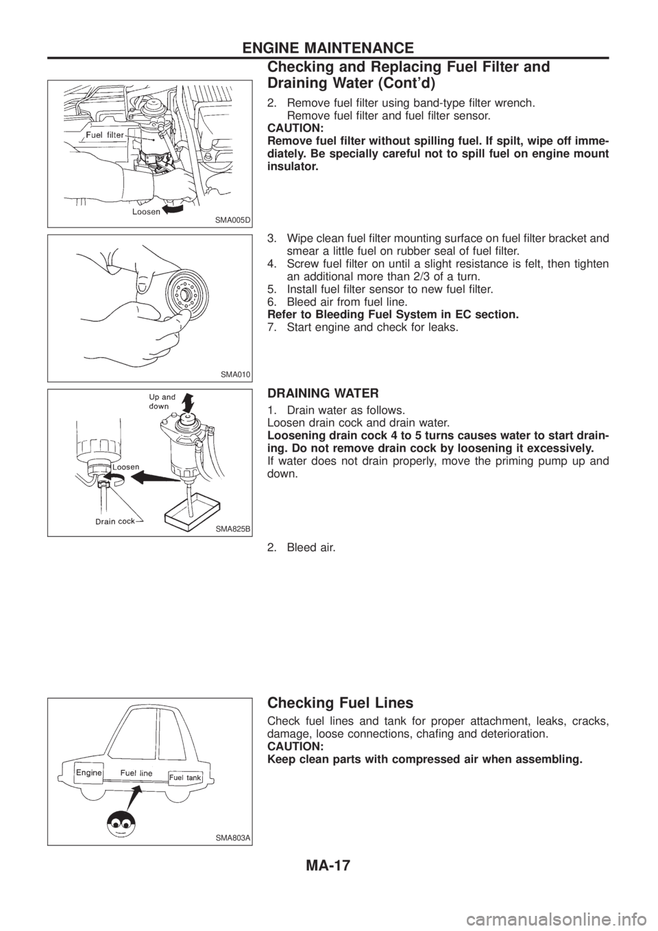
2. Remove fuel ®lter using band-type ®lter wrench.
Remove fuel ®lter and fuel ®lter sensor.
CAUTION:
Remove fuel ®lter without spilling fuel. If spilt, wipe off imme-
diately. Be specially careful not to spill fuel on engine mount
insulator.
3. Wipe clean fuel ®lter mounting surface on fuel ®lter bracket and
smear a little fuel on rubber seal of fuel ®lter.
4. Screw fuel ®lter on until a slight resistance is felt, then tighten
an additional more than 2/3 of a turn.
5. Install fuel ®lter sensor to new fuel ®lter.
6. Bleed air from fuel line.
Refer to Bleeding Fuel System in EC section.
7. Start engine and check for leaks.
DRAINING WATER
1. Drain water as follows.
Loosen drain cock and drain water.
Loosening drain cock 4 to 5 turns causes water to start drain-
ing. Do not remove drain cock by loosening it excessively.
If water does not drain properly, move the priming pump up and
down.
2. Bleed air.
Checking Fuel Lines
Check fuel lines and tank for proper attachment, leaks, cracks,
damage, loose connections, cha®ng and deterioration.
CAUTION:
Keep clean parts with compressed air when assembling.
SMA005D
SMA010
SMA825B
SMA803A
ENGINE MAINTENANCE
Checking and Replacing Fuel Filter and
Draining Water (Cont'd)
MA-17