2006 NISSAN PATROL wheel size
[x] Cancel search: wheel sizePage 62 of 1226
jA
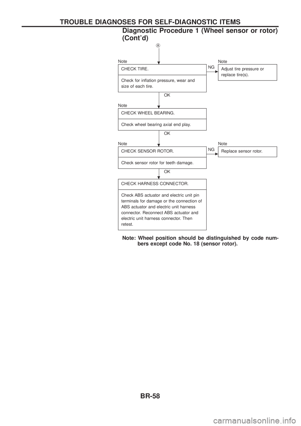
NoteCHECK TIRE.
- ---------------------------------------------------------------------------------------------------------------------------------------------------------------------------------------------------------------------------------------------------------------------------------------------------------------
Check for in¯ation pressure, wear and
size of each tire.
OK
cNG Note
Adjust tire pressure or
replace tire(s).
NoteCHECK WHEEL BEARING.
- ---------------------------------------------------------------------------------------------------------------------------------------------------------------------------------------------------------------------------------------------------------------------------------------------------------------
Check wheel bearing axial end play.
OK
Note CHECK SENSOR ROTOR.
- ---------------------------------------------------------------------------------------------------------------------------------------------------------------------------------------------------------------------------------------------------------------------------------------------------------------
Check sensor rotor for teeth damage.
OK
cNG Note
Replace sensor rotor.
CHECK HARNESS CONNECTOR.
- ---------------------------------------------------------------------------------------------------------------------------------------------------------------------------------------------------------------------------------------------------------------------------------------------------------------
Check ABS actuator and electric unit pin
terminals for damage or the connection of
ABS actuator and electric unit harness
connector. Reconnect ABS actuator and
electric unit harness connector. Then
retest.
Note: Wheel position should be distinguished by code num- bers except code No. 18 (sensor rotor).
.
.
.
.
TROUBLE DIAGNOSES FOR SELF-DIAGNOSTIC ITEMS
Diagnostic Procedure 1 (Wheel sensor or rotor)
(Cont'd)
BR-58
Page 721 of 1226
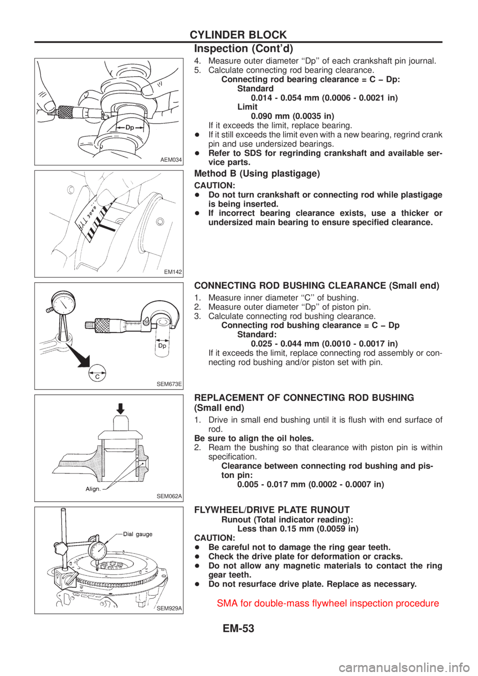
4. Measure outer diameter ``Dp'' of each crankshaft pin journal.
5. Calculate connecting rod bearing clearance.
Connecting rod bearing clearance=CþDp:
Standard
0.014 - 0.054 mm (0.0006 - 0.0021 in)
Limit
0.090 mm (0.0035 in)
If it exceeds the limit, replace bearing.
+If it still exceeds the limit even with a new bearing, regrind crank
pin and use undersized bearings.
+Refer to SDS for regrinding crankshaft and available ser-
vice parts.
Method B (Using plastigage)
CAUTION:
+Do not turn crankshaft or connecting rod while plastigage
is being inserted.
+If incorrect bearing clearance exists, use a thicker or
undersized main bearing to ensure speci®ed clearance.
CONNECTING ROD BUSHING CLEARANCE (Small end)
1. Measure inner diameter ``C'' of bushing.
2. Measure outer diameter ``Dp'' of piston pin.
3. Calculate connecting rod bushing clearance.
Connecting rod bushing clearance=CþDp
Standard:
0.025 - 0.044 mm (0.0010 - 0.0017 in)
If it exceeds the limit, replace connecting rod assembly or con-
necting rod bushing and/or piston set with pin.
REPLACEMENT OF CONNECTING ROD BUSHING
(Small end)
1. Drive in small end bushing until it is ¯ush with end surface of
rod.
Be sure to align the oil holes.
2. Ream the bushing so that clearance with piston pin is within
speci®cation.
Clearance between connecting rod bushing and pis-
ton pin:
0.005 - 0.017 mm (0.0002 - 0.0007 in)
FLYWHEEL/DRIVE PLATE RUNOUT
Runout (Total indicator reading):
Less than 0.15 mm (0.0059 in)
CAUTION:
+Be careful not to damage the ring gear teeth.
+Check the drive plate for deformation or cracks.
+Do not allow any magnetic materials to contact the ring
gear teeth.
+Do not resurface drive plate. Replace as necessary.
AEM034
EM142
SEM673E
SEM062A
SEM929A
CYLINDER BLOCK
Inspection (Cont'd)
EM-53
Page 732 of 1226
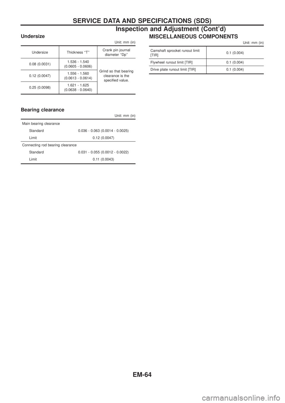
Undersize
Unit: mm (in)
Undersize Thickness ``T''Crank pin journal
diameter ``Dp''
0.08 (0.0031)1.536 - 1.540
(0.0605 - 0.0606)
Grind so that bearing
clearance is the
speci®ed value. 0.12 (0.0047)1.556 - 1.560
(0.0613 - 0.0614)
0.25 (0.0098)1.621 - 1.625
(0.0638 - 0.0640)
Bearing clearance
Unit: mm (in)
Main bearing clearance
Standard 0.036 - 0.063 (0.0014 - 0.0025)
Limit 0.12 (0.0047)
Connecting rod bearing clearance
Standard 0.031 - 0.055 (0.0012 - 0.0022)
Limit 0.11 (0.0043)
MISCELLANEOUS COMPONENTS
Unit: mm (in)
Camshaft sprocket runout limit
[TIR]0.1 (0.004)
Flywheel runout limit [TIR] 0.1 (0.004)
Drive plate runout limit [TIR] 0.1 (0.004)
SERVICE DATA AND SPECIFICATIONS (SDS)
Inspection and Adjustment (Cont'd)
EM-64
Page 736 of 1226
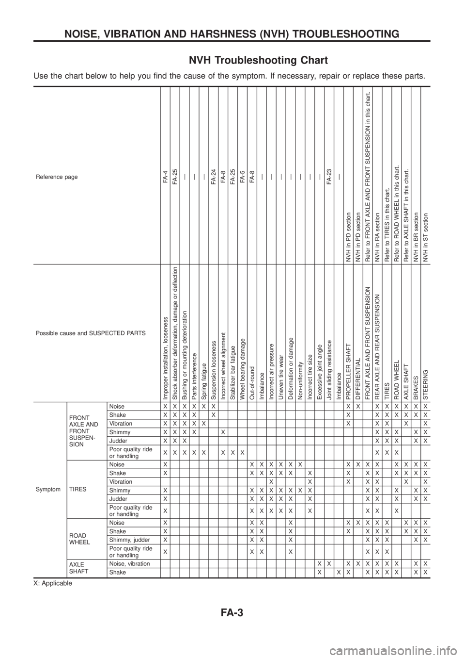
NVH Troubleshooting Chart
Use the chart below to help you ®nd the cause of the symptom. If necessary, repair or replace these parts.
Reference pageFA-4
FA-25
Ð
Ð
Ð
FA-24
FA-8
FA-25
FA-5
FA-8
Ð
Ð
Ð
Ð
Ð
Ð
Ð
FA-23
Ð
NVH in PD section
NVH in PD section
Refer to FRONT AXLE AND FRONT SUSPENSION in this chart.
NVH in RA section
Refer to TIRES in this chart.
Refer to ROAD WHEEL in this chart.
Refer to AXLE SHAFT in this chart.
NVH in BR section
NVH in ST section
Possible cause and SUSPECTED PARTS
Improper installation, looseness
Shock absorber deformation, damage or de¯ection
Bushing or mounting deterioration
Parts interference
Spring fatigue
Suspension looseness
Incorrect wheel alignment
Stabilizer bar fatigue
Wheel bearing damage
Out-of-round
Imbalance
Incorrect air pressure
Uneven tire wear
Deformation or damage
Non-uniformity
Incorrect tire size
Excessive joint angle
Joint sliding resistance
Imbalance
PROPELLER SHAFT
DIFFERENTIAL
FRONT AXLE AND FRONT SUSPENSION
REAR AXLE AND REAR SUSPENSION
TIRES
ROAD WHEEL
AXLE SHAFT
BRAKES
STEERING
SymptomFRONT
AXLE AND
FRONT
SUSPEN-
SIONNoiseXXXXXX XX XXXXXX
ShakeXXXX X X XXXXXX
VibrationXXXXX X XX X X
ShimmyXXXX X XXX XX
Judder X X XXXX XX
Poor quality ride
or handlingXXXXX XXX XXX
TIRESNoise XXXXXXX XXXX XXXX
Shake XXXXXX X X XX XXXX
Vibration X X X X X X X
Shimmy XXXXXXXX XX X XX
Judder XXXXXX X XX X XX
Poor quality ride
or handlingX XXXXX X XX X
ROAD
WHEELNoise X X X XXXXXX XXX
Shake X X X X X X X X X X X
Shimmy, judder X X X X X X X X X
Poor quality ride
or handlingX XX X XXX
AXLE
SHAFTNoise, vibration X XXXXXXX XX
ShakeX XX XXXX XX
X: Applicable
NOISE, VIBRATION AND HARSHNESS (NVH) TROUBLESHOOTING
FA-3
Page 745 of 1226
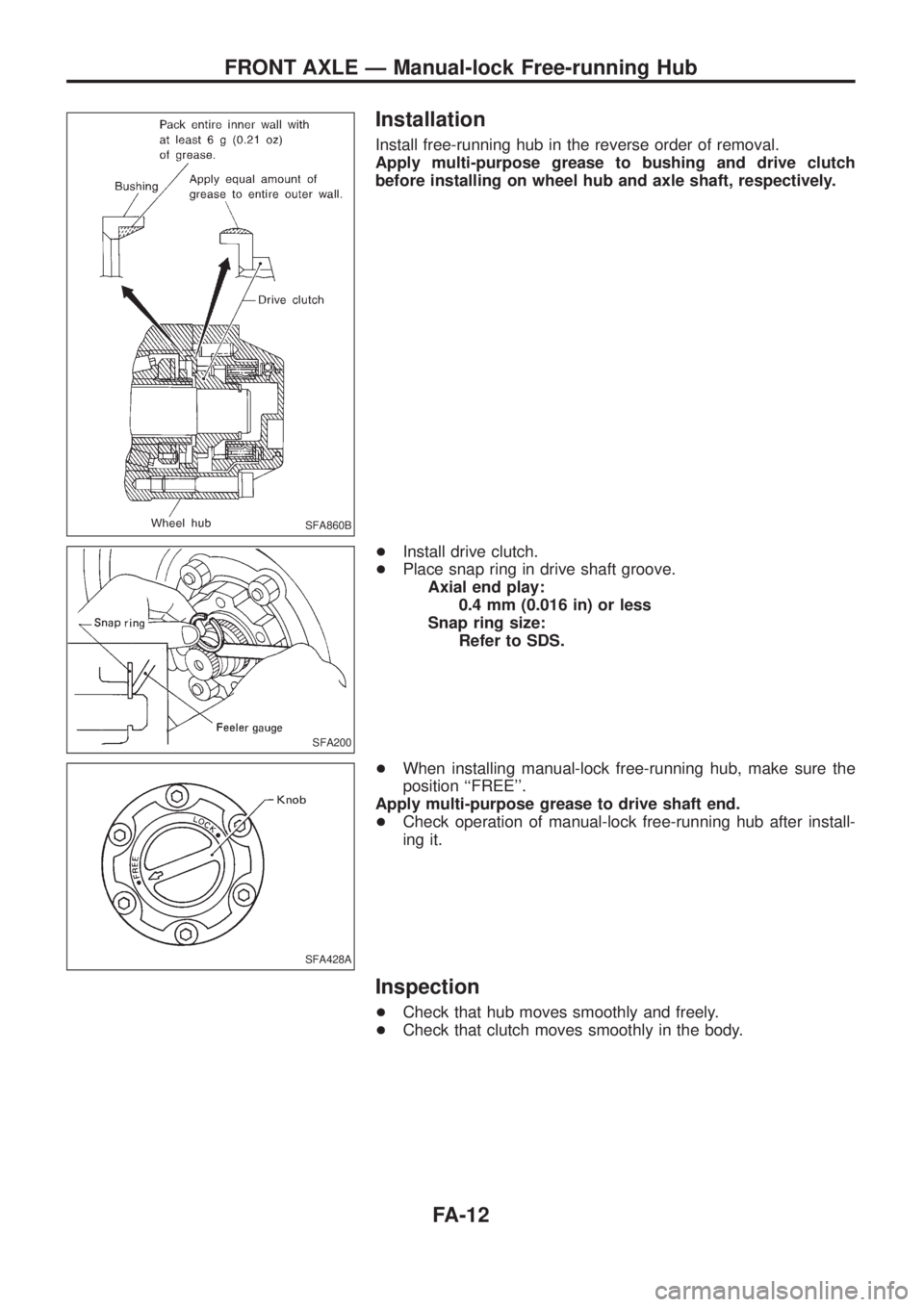
Installation
Install free-running hub in the reverse order of removal.
Apply multi-purpose grease to bushing and drive clutch
before installing on wheel hub and axle shaft, respectively.
+Install drive clutch.
+Place snap ring in drive shaft groove.
Axial end play:
0.4 mm (0.016 in) or less
Snap ring size:
Refer to SDS.
+When installing manual-lock free-running hub, make sure the
position ``FREE''.
Apply multi-purpose grease to drive shaft end.
+Check operation of manual-lock free-running hub after install-
ing it.
Inspection
+Check that hub moves smoothly and freely.
+Check that clutch moves smoothly in the body.
SFA860B
SFA200
SFA428A
FRONT AXLE Ð Manual-lock Free-running Hub
FA-12
Page 746 of 1226
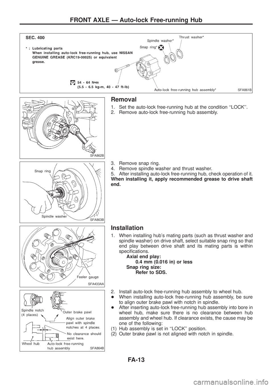
Removal
1. Set the auto-lock free-running hub at the condition ``LOCK''.
2. Remove auto-lock free-running hub assembly.
3. Remove snap ring.
4. Remove spindle washer and thrust washer.
5. After installing auto-lock free-running hub, check operation of it.
When installing it, apply recommended grease to drive shaft
end.
Installation
1. When installing hub's mating parts (such as thrust washer and
spindle washer) on drive shaft, select suitable snap ring so that
end play between drive shaft and its mating parts is within
speci®cations.
Axial end play:
0.4 mm (0.016 in) or less
Snap ring size:
Refer to SDS.
2. Install auto-lock free-running hub assembly to wheel hub.
+When installing auto-lock free-running hub assembly, be sure
to align outer brake pawl with notch in spindle.
+After inserting auto-lock free-running hub assembly into bore in
wheel hub, make sure there is no clearance between hub
assembly and wheel hub. If clearance exists, the cause may be
one of the following:
(1) Hub assembly is set in ``LOCK'' position.
(2) Outer brake pawl is not aligned with notch in spindle.
SFA861B
SFA862B
SFA863B
SFA433AA
SFA864B
FRONT AXLE Ð Auto-lock Free-running Hub
FA-13
Page 811 of 1226
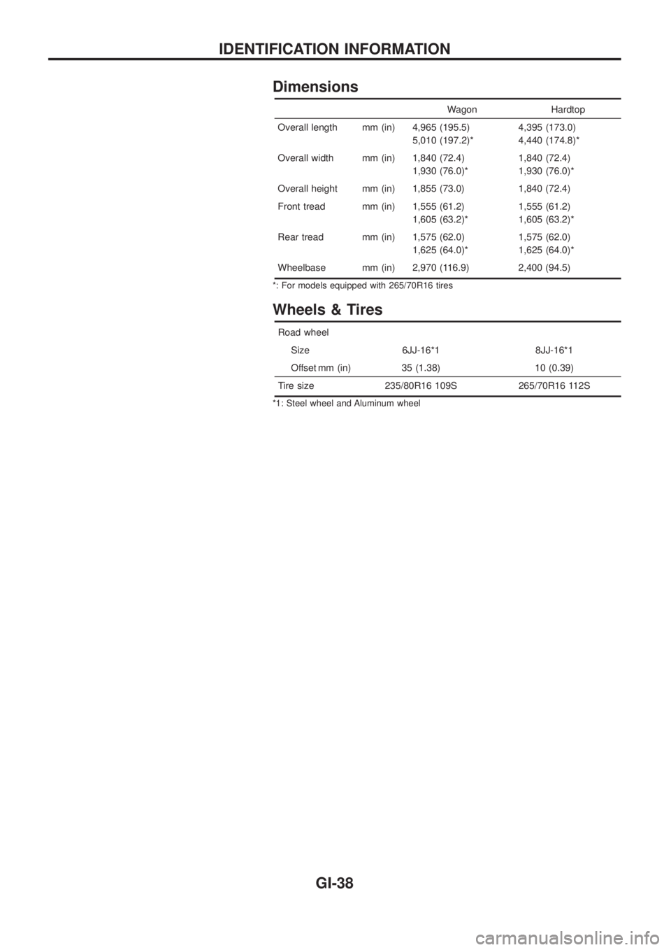
Dimensions
Wagon Hardtop
Overall length mm (in) 4,965 (195.5)
5,010 (197.2)*4,395 (173.0)
4,440 (174.8)*
Overall width mm (in) 1,840 (72.4)
1,930 (76.0)*1,840 (72.4)
1,930 (76.0)*
Overall height mm (in) 1,855 (73.0) 1,840 (72.4)
Front tread mm (in) 1,555 (61.2)
1,605 (63.2)*1,555 (61.2)
1,605 (63.2)*
Rear tread mm (in) 1,575 (62.0)
1,625 (64.0)*1,575 (62.0)
1,625 (64.0)*
Wheelbase mm (in) 2,970 (116.9) 2,400 (94.5)
*: For models equipped with 265/70R16 tires
Wheels & Tires
Road wheel
Size 6JJ-16*1 8JJ-16*1
Offset mm (in) 35 (1.38) 10 (0.39)
Tire size 235/80R16 109S 265/70R16 112S
*1: Steel wheel and Aluminum wheel
IDENTIFICATION INFORMATION
GI-38
Page 953 of 1226
ROOM/L - Wiring diagram ..............................EL-95
Radiator ..........................................................LC-14
Radio - See Audio.........................................EL-168
Rear axle (disc brake type) ..............................RA-6
Rear bumper .....................................................BT-6
Rear case (Transfer) .......................................TF-10
Rear combination lamp removal and
installation ...................................................BT-26
Rear cover packing replacement diff..............PD-11
Rear disc brake ..............................................BR-24
Rear door ........................................................BT-10
Rear fog lamp .................................................EL-80
Rear heater - Wiring diagram ........................HA-14
Rear seat belt ...................................................RS-5
Rear seat ........................................................BT-35
Rear side window ...........................................BT-44
Rear suspension ............................................RA-12
Rear washer..................................................EL-145
Rear window defogger ..................................EL-158
Rear window ...................................................BT-42
Rear wiper.....................................................EL-145
Refrigerant connection precaution ...................HA-2
Refrigerant discharging evacuating
charging ....................................................HA-113
Refrigerant general precaution.........................HA-2
Refrigerant lines ...........................................HA-117
Refrigeration cycle ..........................................HA-11
Release bearing (clutch) .................................CL-11
Removal and installation (Transfer) ..................TF-8
Reverse idler shaft (M/T) ...............................MT-10
Reverse lamp switch (M/T) - See
Back-up lamp switch (M/T)...........................MT-4
Reverse main gear (M/T) ...............................MT-10
Ring gear diff. inspection ...............................PD-19
Road wheel size ..............................................GI-38
Roof trim .........................................................BT-20
Room lamp - See Interior lamp ......................EL-93
Rotor disc (front) .............................................FA-14
S
S/LOCK - Wiring diagram .............................EL-215
S/SIG - Wiring diagram ................................EC-162
SAE J1930 terminology list .............................GI-43
SEAT - Wiring diagram .................................EL-190
SMJ (super multiple junction) .......................EL-317
SROOF - Wiring diagram .............................EL-186
SRS - See Supplemental Restraint
System ..........................................................RS-8
SRS Trouble diagnoses .................................RS-22
STAB - Wiring diagram ..................................RA-18
START - Wiring diagram .................................EL-45
Screw jack .......................................................GI-39
Seal - See Exterior .........................................BT-26
Seat belt inspection .......................................MA-27
Seat belt pre-tensioner disposal ....................RS-17
Seat belt pre-tensioner ...................................RS-12
Seat belt, front ..................................................RS-2
Seat belt, rear...................................................RS-5Seat, front .......................................................BT-32
Seat, rear ........................................................BT-35
Seat, second (2nd) .........................................BT-35
Seat, third (3rd) ...............................................BT-37
Second (2nd) seat ..........................................BT-35
Self-diagnostic results ....................................EC-31
Shift control (Transfer) ....................................TF-12
Shift control components (M/T) ......................MT-12
Shift fork (M/T) ...............................................MT-12
Shift lever .......................................................MT-12
Shock absorber (front) ....................................FA-25
Shock absorber (rear) ....................................RA-14
Side bearing preload (front ®nal drive
4WD)...........................................................PD-27
Side bearing preload diff. ...............................PD-27
Side trim ..........................................................BT-14
Side window - See Rear side window ............BT-44
Speedometer.................................................EL-102
Spiral cable.....................................................RS-13
Stabilizer bar (front) ........................................FA-25
Stabilizer bar (rear) ........................................RA-15
Stabilizer release device - Wiring
diagram .......................................................RA-18
Stabilizer release device ................................RA-16
Standardized relay ............................................EL-3
Start signal ...................................................EC-162
Starter .............................................................EL-51
Starting system ...............................................EL-45
Steering gear and linkage inspection ............MA-26
Steering linkage ..............................................ST-19
Steering switch................................................EL-59
Steering wheel and column ..............................ST-8
Steering wheel play ..........................................ST-4
Steering wheel turning force .............................ST-6
Striking rod (M/T) ...........................................MT-12
Sub-gear (M/T) ...............................................MT-10
Sunload sensor ............................................HA-107
Sunroof, electric ............................................EL-186
Sunroof............................................................BT-39
Super lock .....................................................EL-211
Supplemental Restraint System .......................RS-8
Supplemental restraint system - Wiring
diagram .......................................................RS-27
Symbols and abbreviations ...............................GI-7
Synchronizer (M/T) .........................................MT-10
T
TCV - Wiring diagram ..................................EC-100
Tachometer ...................................................EL-102
Thermometer .................................................EL-116
Thermostat ......................................................LC-12
Third (3rd) seat ...............................................BT-37
Three way catalyst precautions.........................GI-4
Throttle control solenoid valve .....................EC-155
Throttle control solenoid valve .....................EC-161
Throwout bearing - See Clutch release
bearing ........................................................CL-11
Thrust washer selection diff. ..........................PD-27
ALPHABETICAL INDEX
IDX-6