Page 81 of 800
STARTING SYSTEM
ENGINE ELECTRICAL16-19
STARTING SYSTEM
GENERAL INFORMATIONM1162000100202
If the ignition switch is turned to the "START" posi-
tion, current flows in the pull-in and holding coils pro-
vided inside magnetic switch, attracting the plunger,
When the plunger is attracted, the lever connected to
the plunger is actuated to engage the starter clutch.
On the other hand, attracting the plunger will turn on
the magnetic switch, allowing the "B" terminal and
"M" terminal to conduct. Thus, current flows to
engage the starter motor.
When the ignition switch is returned to the "ON" posi-
tion after starting the engine, the starter clutch is dis-
engaged from the ring gear.
An overrunning clutch is provided between the pinion
and the armature shaft, to prevent damage to the
starter.
SYSTEM DIAGRAM
AK202970
Pull-in coilHolding coil
Plunger
Lever
Pinion gear
Overrunning clutch
Yo k e
Brush Armature
Ignition switch
Battery
+
–
AB
B
M S
Page 84 of 800
Page 88 of 800
Page 89 of 800

STARTING SYSTEM
ENGINE ELECTRICAL16-27
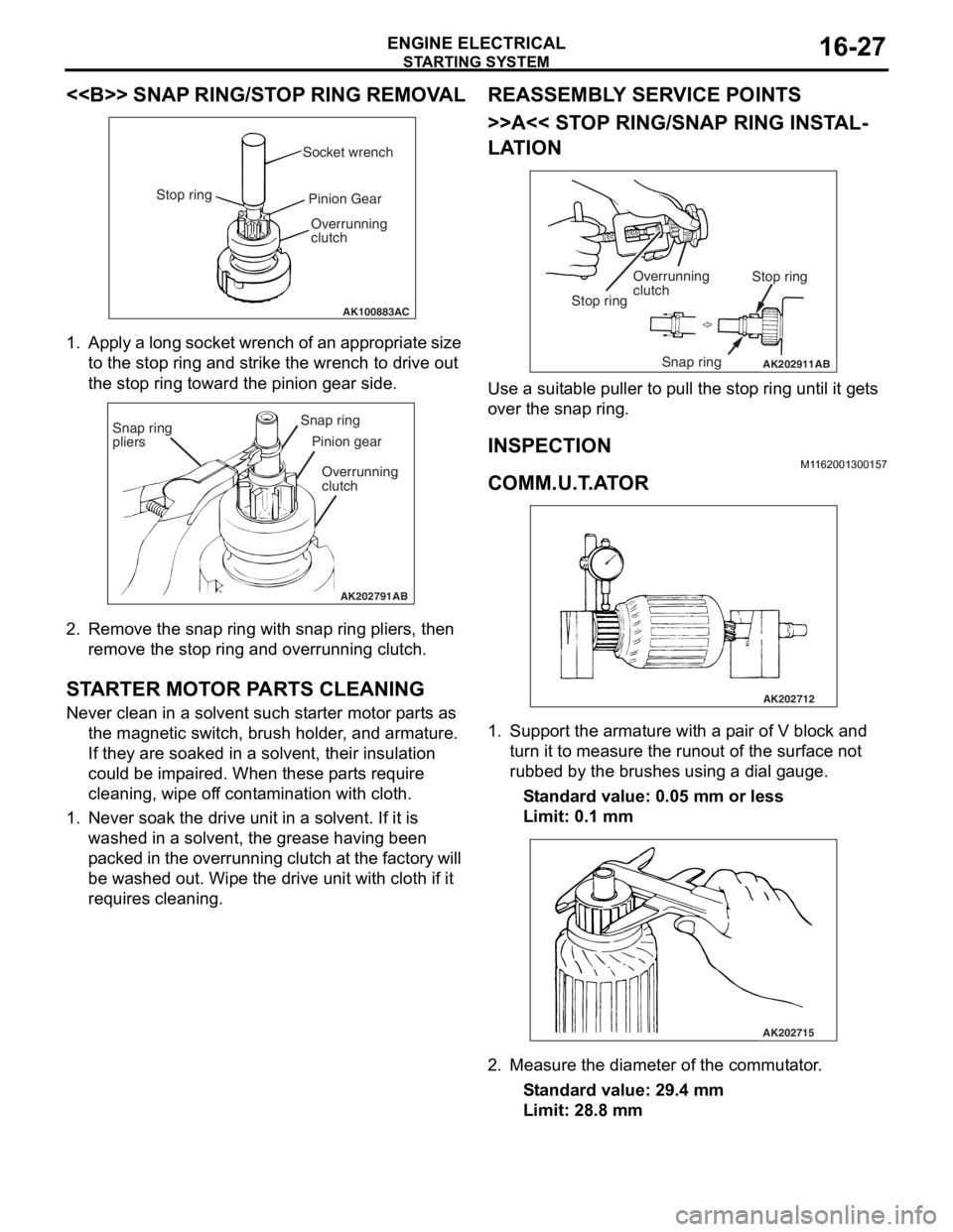
<> SNAP RING/STOP RING REMOVAL
AK100883AC
Socket wrench
Stop ring Pinion Gear
Overrunning
clutch
1. Ap ply a lo ng socket wr ench o f a n ap pro p ria t e size
to the stop ring and strike th e wrench to drive out
th e sto p ring toward th e pin i on g ear side.
AK202791
Snap ring
pliersSnap ring
Pinion gear
Overrunning
clutch
AB
2. Remove the snap ring with sna p ring pliers, th en
remove the stop ring an d overrunning clutch.
STARTER MOT O R P ARTS CLEANING
Never clean in a solvent such st arte r moto r p a rt s as
th e ma gnetic switch, brush hold e r , and arma ture.
If they are soake d in a solven t, their insulat i on
could be imp a ire d . When these p a rt s requ ire
clean ing, wipe of f co nt a m in ation with cloth .
1.Never so ak th e drive un it in a solve n t. If it is
washed in a solvent, th e grea se ha vin g been
p a cke d in th e over run n ing clutch at t he fa ct or y will
be washe d out. Wipe t he drive u n it with cloth if it
req u ires cleaning.
REASSEM BL Y SER V ICE POINT S
>>A<< STOP RING/SNAP RING INST AL-
LATION
AK202911
Overrunning
clutch Stop ring
Snap ring
Stop ring
AB
Use a suit
able puller to pull the stop ring u n til it ge t s
over t
he snap ring.
INSPECTION
M1162 0013 0015 7
COMM.U.T .A T O R
AK202712
1.Sup port the arma ture with a p a ir o f V block a nd
tu rn it t o mea s ure the run out of the surface not
ru bbed b y the brushes u s in g a dial g auge.
St andard va lue: 0.0 5 mm o r l ess
Limit: 0.1 mm
AK202715
2.Measure the diameter o f the commut ator .
St andard va lue: 29 .4 mm
Limit: 28.8 mm
Page 90 of 800

AK202711
SegmentUndercut
Mica
AB
ST ARTING SYS TEM
ENGINE ELECTRICAL16-28
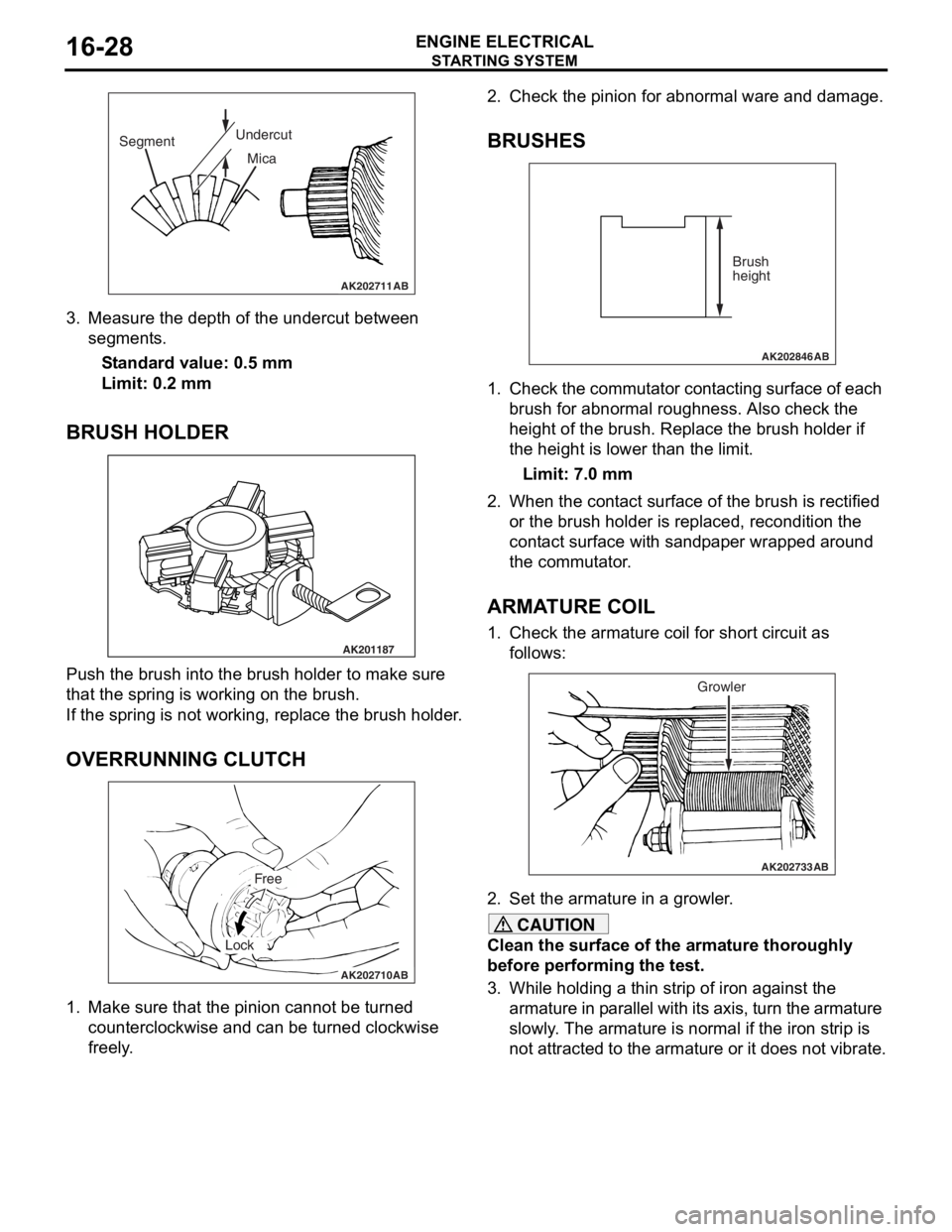
3.Measure the depth of the undercut be twe en
segment s.
St andard va lue: 0.5 mm
Limit: 0.2 mm
BRUSH HOLDER
AK201187
Push th e brush in to the b r ush hold e r to make sure
that the
spring is working o n the b r ush.
If the spring is not working, repla c e th e brush holder .
OVERRUNNING CLUTCH
AK202710
Free
Lock
AB
1.Make sure that th e pin i on canno t be tu rned
counte r clo ckwise a nd ca n be tu rned clockwise
fre e ly .
2.Check t he pinion for abn ormal ware an d damage.
BRUSHES
AK202846
Brush
height
AB
1.Che ck the commut ator con t a c tin g surface of each
b r ush f o r abno rmal rough ness. Also ch eck the
h e ight of the brush . Replace th e brush holder if
th e height is lo we r than t he limit.
Limit: 7.0 mm
2.Wh en the con t act su rface of the brush is rectified
o r the bru s h h o lder is re placed, re cond itio n the
cont act surfa c e wit h san d p a p e r wrapped around
th e co mmu t a t o r .
ARMATURE COIL
1.Check t he armature coil for short circuit a s
fo llows:
AK202733
Growler
AB
2.Set the armature in a growler .
CAUTION
Clean the surface of the armature thoroughly
before performing the test.
3. While holding a thin strip of iron against the
armature in parallel with it s axis, turn the armature
slowly. The armature is normal if the iron strip is
not attracted to the armature or it does not vibrate.
Page 127 of 800
21-1
GROUP 21
CLUTCH
CONTENTS
CLUTCH . . . . . . . . . . . . . . . . . . . . . . . . . . . . . . . . . . . . . . . . . . .21A
CLUTCH OVERHAUL . . . . . . . . . . . . . . . . . . . . . . . . . . . . . . . . .21B
Page 560 of 800
INVECS-II 4A/T
CIRCUIT DIAGRAMS90-96
INVECS-II 4A/T <4G1 (LHD)> (CONTINUED)
A/T
CONTROL
RELAY
A/T CONTROL
SOLENOID
VALVE ASSEMBLY
ENGINE CONTROL
SYSTEM
ENGINE-
A/T-ECU
NOTE
:
:
:
:
: UNDERDRIVE
SOLENOID VALVE
SECOND
SOLENOID VALVE
DAMPER CLUTCH
CONTROL
SOLENOID VALVE OVERDRIVE
SOLENOID VALVE
LOW AND REVERSE
SOLENOID VALVE
A/T FLUID
TEMPERATURE
SENSOR
FRONT
SIDE
Page 566 of 800
INVECS-II 4A/T
CIRCUIT DIAGRAMS90-102
INVECS-II 4A/T <4G1 (RHD)> (CONTINUED)
A/T CONTROL
SOLENOID
VALVE ASSEMBLY
NOTE
:
:
:
:
: UNDERDRIVE
SOLENOID VALVE
SECOND
SOLENOID VALVE
DAMPER CLUTCH
CONTROL
SOLENOID VALVE OVERDRIVE
SOLENOID VALVE
LOW AND REVERSE
SOLENOID VALVE
A/T
CONTROL
RELAY
ENGINE CONTROL
SYSTEM
ENGINE-
A/T-ECU
FRONT
SIDE
A/T FLUID
TEMPERATURE
SENSOR