2006 MITSUBISHI LANCER block
[x] Cancel search: blockPage 17 of 800

LUBRICANT
ENGINE COOLING14-3
LUBRICANT
M1141000400338
ItemSpecified coolantQuantity L
Engine coolant (including
condense tank)DIAQUEEN SUPER LONG LIFE COOLANT
or an equivalent4G15.0
4G67.0
SEALANTS
M1141000500324
ItemSpecified sealant
Cylinder block drain plug3M Nut Locking Part No.4171 or equivalent
Water pump <4G1>, Thermostat case
<4G6>, Cooling water outlet hose fitting
<4G6>MITSUBISHI GENUINE Part No.MD970389 or equivalent
SPECIAL TOOLS
M1141000600581
ToolNumberNameUse
B991502
MB991502M.U.T. -II sub
assemblyReading diagno sis co de
Page 35 of 800

ON-VEHICLE SERVICE
ENGINE COOLING14-21
ON-VEHICLE SERVICE
ENGINE COOLANT LEAK CHECKM1141001000300
WARNING
When pressure testing the cooling system,
slowly release cooling system pressure to
avoid getting burned by hot coolant.
CAUTION
•Be sure to completely clean away any mois-
ture from the places checked.
•When the tester is taken out, be careful not to
spill any coolant.
•
ACX01844
Cap adapter
Adapter
AC
Be careful when installing and removing the
tester and when testing not to deform the
filler neck of the radiator.
1. Check that the coolant leve l is up to the filler neck.
Install a radiator tester and apply 160 kPa
pressure, and then check for leakage from the
radiator hose or connections.
2. If there is leakage, repair or replace the
appropriate part.
RADIATOR CAP VALVE OPENING
PRESSURE CHECK
M1141001300389
NOTE: Be sure that the cap is clean before test-
ing. Rust or other foreign material on the cap seal
will cause an improper reading.
AC211643AB
Cap adapter
1. Use a cap adapter to attach the cap to the tester.
2. Increase the pressure until the indicator of the gauge stops moving.
Minimum limit: 83 kPa
Standard value: 93 − 123 kPa
3. Replace the radiator cap if the reading does not remain at or above the limit.
ENGINE COOLANT REPLACEMENT
M1141001200434
WARNING
When removing the radiator cap, use care to
avoid contact with hot coolant or steam.
Place a shop towel over the cap and turn the
cap counterclockwise a little to let the pres
-
sure escape through the vinyl tube. After
relieving the steam pres sure, remove the cap
by slowly turning it counterclockwise.
1. Drain the water from the radiator, heater core and
engine after unplugging the radiator drain plug
and removing the radiator cap.
AC208283AC
Cylinder block
drain plug
<4G1>
Inlet side
AC303355
<4G6>
Inlet side
Cylinder block
drain plug
AB
2. Drain the water in the water jacket by unplugging the drain plug of the cylinder block.
3. Remove the radiator condenser tank and drain
the coolant.
4. Drain the coolant then clean the path of the coolant by injecting water into the radiator from
the radiator cap area.
Page 36 of 800

AC200625
Cylinder block
drain plug
AC
ON-VEHICLE SER VICE
ENGINE COOLING14-22
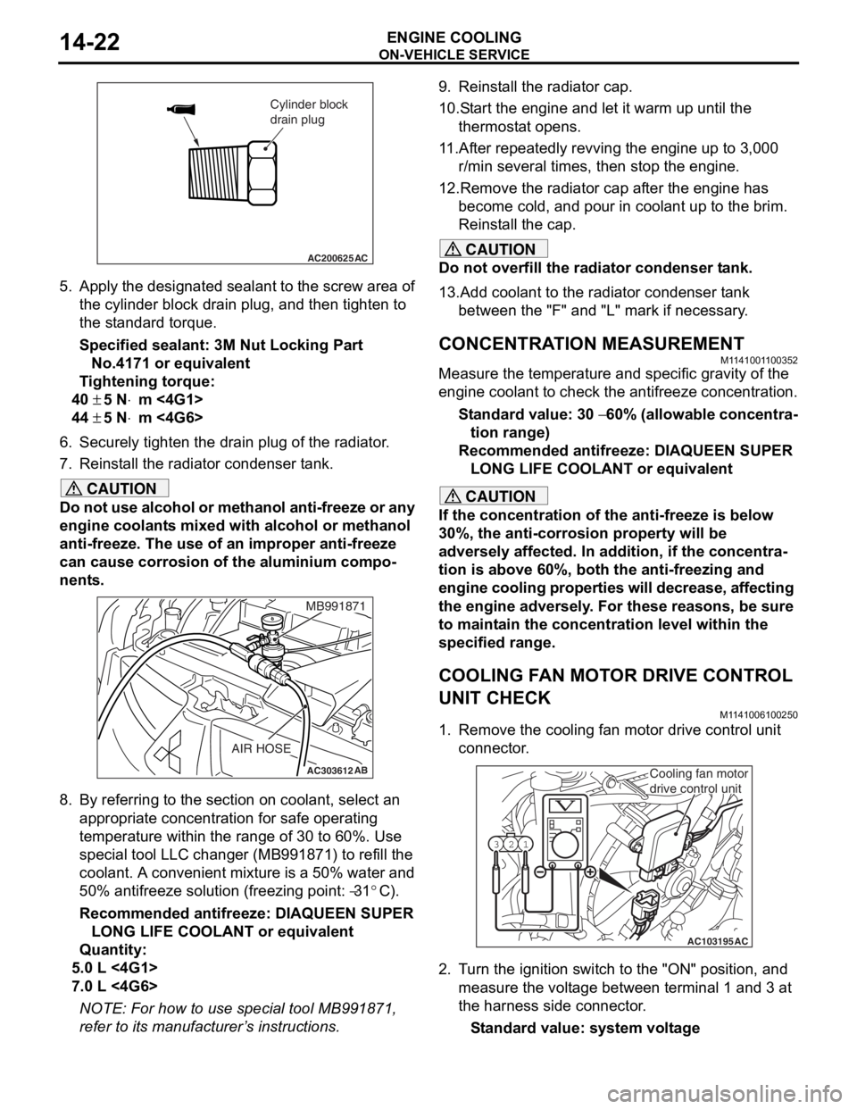
5.App l y the designa ted sealant to t he scre w area of
th e cylin der block drain plu g , and then tighten to
th e st and ard torq ue.
Sp e c ified s ealant: 3 M Nut Loc king Part
No. 4171 o r e quivale n t
Ti ghtenin g torque:
40 ± 5 N⋅m <4G1>
44 ± 5 N⋅m <4G6>
6.Securely tighten t he drain plug of t he radiator .
7.Reinst all the ra diato r con denser t ank.
CAUTION
Do not use alcohol or methanol anti-freeze or any
engine coolants mixed with alcohol or methanol
anti-freeze. The use of an improper anti-freeze
can cause corrosion of the aluminium compo
-
nents.
AC303612AB
MB991871
AIR HOSE
8. By referring to the section on coolant, select an
appropriate concentration for safe operating
temperature within the range of 30 to 60%. Use
special tool LLC changer (MB991871) to refill the
coolant. A convenient mixture is a 50% water and
50% antifreeze solution (freezing point:
−31°C).
Recommended antifreeze: DIAQUEEN SUPER LONG LIFE COOLANT or equivalent
Quantity:
5.0 L <4G1>
7.0 L <4G6>
NOTE: For how to use special tool MB991871,
refer to its manufacturer’s instructions.
9. Reinstall the radiator cap.
10.Start the engine and let it warm up until the thermostat opens.
11.After repeatedly revving the engine up to 3,000 r/min several times, then stop the engine.
12.Remove the radiator cap after the engine has become cold, and pour in coolant up to the brim.
Reinstall the cap.
CAUTION
Do not overfill the radiator condenser tank.
13.Add coolant to the radiator condenser tank between the "F" and "L" mark if necessary.
CONCENTRATION MEASUREMENT
M1141001100352
Measure the temperature and specific gravity of the
engine coolant to check the antifreeze concentration.
Standard value: 30 − 60% (allowable concentra-
tion range)
Recommended antifreeze: DIAQUEEN SUPER
LONG LIFE COOLANT or equivalent
CAUTION
If the concentration of the anti-freeze is below
30%, the anti-corrosion property will be
adversely affected. In addition, if the concentra
-
tion is above 60%, both the anti-freezing and
engine cooling properties will decrease, affecting
the engine adversely. For these reasons, be sure
to maintain the concentration level within the
specified range.
COOLING FAN MOTOR DRIVE CONTROL
UNIT CHECK
M1141006100250
1. Remove the cooling fan motor drive control unit connector.
AC103195
Y1716AU
1
23
AC
Cooling fan motor
drive control unit
2. Turn the ignition switch to the "ON" position, and
measure the voltage between terminal 1 and 3 at
the harness side connector.
Standard value: system voltage
Page 89 of 800

STARTING SYSTEM
ENGINE ELECTRICAL16-27
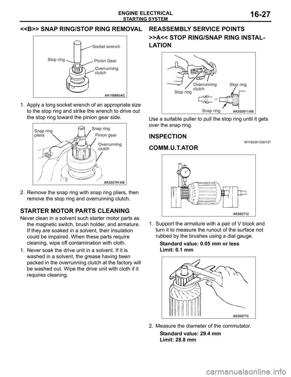
<> SNAP RING/STOP RING REMOVAL
AK100883AC
Socket wrench
Stop ring Pinion Gear
Overrunning
clutch
1. Ap ply a lo ng socket wr ench o f a n ap pro p ria t e size
to the stop ring and strike th e wrench to drive out
th e sto p ring toward th e pin i on g ear side.
AK202791
Snap ring
pliersSnap ring
Pinion gear
Overrunning
clutch
AB
2. Remove the snap ring with sna p ring pliers, th en
remove the stop ring an d overrunning clutch.
STARTER MOT O R P ARTS CLEANING
Never clean in a solvent such st arte r moto r p a rt s as
th e ma gnetic switch, brush hold e r , and arma ture.
If they are soake d in a solven t, their insulat i on
could be imp a ire d . When these p a rt s requ ire
clean ing, wipe of f co nt a m in ation with cloth .
1.Never so ak th e drive un it in a solve n t. If it is
washed in a solvent, th e grea se ha vin g been
p a cke d in th e over run n ing clutch at t he fa ct or y will
be washe d out. Wipe t he drive u n it with cloth if it
req u ires cleaning.
REASSEM BL Y SER V ICE POINT S
>>A<< STOP RING/SNAP RING INST AL-
LATION
AK202911
Overrunning
clutch Stop ring
Snap ring
Stop ring
AB
Use a suit
able puller to pull the stop ring u n til it ge t s
over t
he snap ring.
INSPECTION
M1162 0013 0015 7
COMM.U.T .A T O R
AK202712
1.Sup port the arma ture with a p a ir o f V block a nd
tu rn it t o mea s ure the run out of the surface not
ru bbed b y the brushes u s in g a dial g auge.
St andard va lue: 0.0 5 mm o r l ess
Limit: 0.1 mm
AK202715
2.Measure the diameter o f the commut ator .
St andard va lue: 29 .4 mm
Limit: 28.8 mm
Page 105 of 800

IGNITION SYSTEM
ENGINE ELECTRICAL16-43
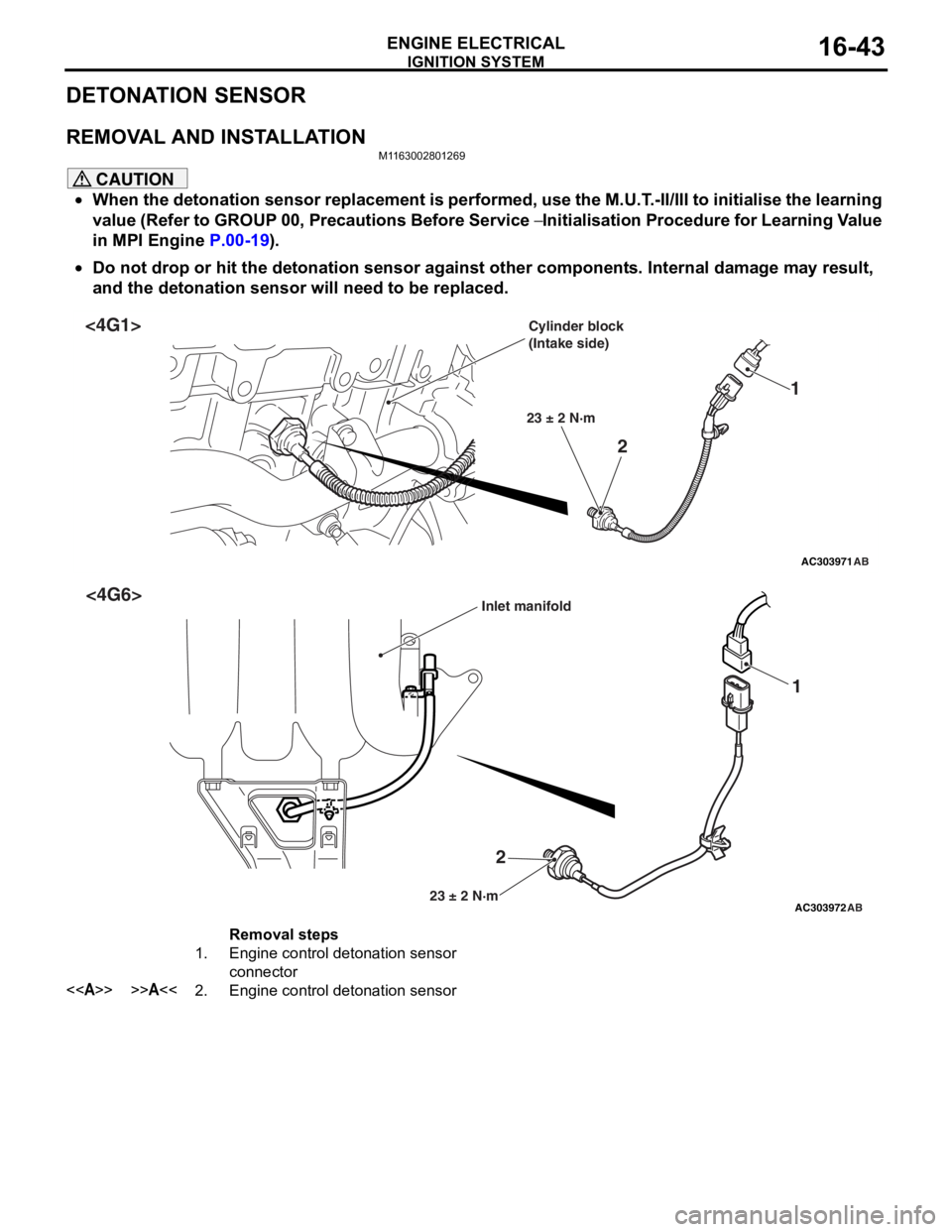
DETONATION SENSOR
REMOVAL AND INSTALLATION
M1163002801269
CAUTION
•When the detonation sensor replacement is performed, use the M.U.T.-II/III to initialise the learning
value (Refer to GROUP 00, Precautions Before Service
− Initialisation Procedure for Learning Value
in MPI Engine
P.00-19).
•
AC303971
2 1
23 ± 2 N·m
AB
<4G1>Cylinder block
(Intake side)
AC303972
2 1
23 ± 2 N·mAB
<4G6>Inlet manifold
Removal steps
1.Engine control detonation sensor
connector
<>>>A<<2.Engine control detonation sensor
Do not drop or hit the detonation sensor against other components. Internal damage may result,
and the detonation sensor will need to be replaced.
Page 117 of 800

EMISSION CONTROL
ENGINE AND EMISSION CONTROL17-11
2. Plug the nipple from which the vacuum hose was removed.
3. When the engine is cold or hot, apply a vacuum of 53 kPa, and check the condition of the vacuum.
When engine is cold
(Engine coolant temperature: 40°C or less)
Engine conditionNormal condition
At idleVacuum is maintained.
3,000 r/min
When engine is hot
(Engine coolant temperature: 80°C or higher)
Engine conditionNormal condition
At idleVacuum is maintained.
3,000 r/min (within 3
minutes after engine
starts)Vacuum will leak.
PURGE PORT VACUUM CHECKM1173001500177
AK300773
<4G1>
AB
Plug
Vacuum hose
AK300774
<4G6>
AB
Plug
Vacuum hose
1.Disco nnect th e vacuum ho se (red st ripe) from the
throttle body and connect a hand vacuum pump to
th e nip p le.
2.Plu g the vacuum hose (red stripe).
AK100011AC
Vac-
uum
Engine speed (r/min)
3.S t art the engine.
4.Check t hat a f a irly co nst ant n egative p r essure is
g enerate d regard l ess of the en gine spee d.
5.If no neg ative pressur e is genera t ed, th e port is
p r obably blocked an d sh ould be cleane d.
PURGE CONTROL SOLENOID VA L V E
CHECK
M1173 0017 0019 3
NOTE: Whe n discon nect i ng th e va cuum hose,
always make a mark so th at it can be reconnected at
original p o sition.
AK100012AC
Battery
A
AK100013
1.
Disco nnect the vacu um h o se f r om th e solenoid
valve.
2.Disco nnect the ha rness connector .
3.Con nect a ha nd vacu um pump to nipp le (A) of the
solen o id valve (ref e r to th e ill ust r ation at le f t ).
4.Check a i rtig htness b y app lying a vacuum with
volt age applied d i rectly from t he batt e ry to the
p u rge con t rol so leno id valve an d without app lying
volt age .
Page 122 of 800

EMISSION CONTROL
ENGINE AND EMISSION CONTROL17-16
5. Replace the gasket, and tighten to the specified torque.
Tightening torque:
<4G1> 21 ± 4 N⋅m
<4G6> 20 ± 2 N⋅m
EGR PORT VACUUM CHECK <4G1>M1173002900167
AK300784AB
Green strip
1.Disco nnect the vacu um ho se (Green stripe) from
th e t h ro tt le b o d y EGR va cuu m ni pp le an d co nn ec t
a hand vacu um p u mp to the nipple.
2.Plu g the vacuum hose (Gree n stripe).
AK201224AB
Vac-
uum
Engine speed (r/min)
3.S t art the engin e and check t hat, af ter ra ising th e
engine spe ed by ra cin g the e ngine, p u rge vacuu m
raises according to engine speed.
NOTE: If ther e is a prob lem with change in vac-
uum, the t h rottle bod y p u rge port may be clo gged
an
d requ ire clean ing.
EGR PORT VA CUUM CHECK <4G6>M1173 0029 0015 6
AK300786AB
White stripe
1.Disco nnect the vacu um h o se (W hite strip e ) from
th e t h ro tt le b o d y EGR va cuu m ni pp le an d co nn ec t
a hand vacuum p u mp to the nipple.
2.Plug the vacuum hose (White stripe).
AK100011AC
Vac-
uum
Engine speed (r/min)
3.S t art the engine.
4.Check that a fairly const a nt n egative is gene rated
re gardle s s of the engine sp eed.
5.If no neg ative pressur e is genera t ed, th e port is
p r obably blocked an d sh ould be cleane d.
EGR CONTROL SOLENOID VA L V E
CHECK <
4 G1 >
M1173 0031 0023 8
NOTE: Whe n discon nect i ng th e va cuum hose,
always make a mark so th at it can be reconnected at
original p o sition.
AKX00351
A
B
AE
Battery
1. Disco nnect the vacu um h o se f r om th e solenoid
valve.
2.Disco nnect the ha rness connector .
3.Con nect a ha nd vacu um pump to nipp le (A) of the
solen o id valve (ref e r to th e ill ust r ation at le f t ).
4.Check a i r tightness b y ap plying a vacuum with
volt age applied d i rectly from t he batt e ry to the
EGR cont rol solen o id valve and withou t applyin g
volt age .
Battery voltageNormal condition
AppliedVa c u u m l e a k s
Not appliedVacuum maintained
Page 301 of 800

DOOR
BODY42-29
3. If the operation current is outside the standard value, refer to GROUP 54B, Troubleshooting
P.54B-15, refer to GROUP 54C, Troubleshooting
P.54C-4.
POWER WINDOW RELAY CHECKM1429001800202
AC305140
123
4
5
1 3
4
5
AB
Junction block
(front view)
Power window relayPower window
relay
Bat t ery
voltage
Teste r
co
nnectionSpecified
condition
Not applied4 − 5Ope n ci rcui t
•Connect
te
rmin al No. 3
an
d the
ne
gative
ba
ttery
te
rmin al.
•Connect
te
rmin al No. 1
an
d the
positive batt
e ry
te
rmin al.
Less than 2
ohms
CIRCUIT BREAKER (INCORPORA T ED IN
THE POW
E R W I NDOW MOT O R)
INSPECTION
M14290010 0027 3
1.Pull the p o wer windo w switch to th e UP position
to f u lly close the do or windo w g l ass, an d ke ep
pullin g the switch for 1 0 addition al secon d s.
2.Rele ase the power window switch from t he UP
position an d immediately pre ss it to t he DOW N
position. Th e con d ition of the circu i t brea ker is
goo d if t he doo r window g l ass st art s to mo ve
downward s with in 60 seconds.
POWER WI NDOW CHECKM14290044 0020 3
Check the system a s de scribed b e low . I f the system
does not work, car
r y out troublesh ootin g. Refer to
GROUP 54
B, T r ouble s hoo ting
P.54B-15 or GROUP
54C, T r oublesh ootin g P.54C-4.
•Operate the powe r wind ow switch of e a ch se at to
check that
the power window works.
•Tu rn o n the power wind ow lock switch of the
power wind
ow main swit ch, and ope rate the front
p
a ssenger's and rear power window su b switches
to check th
at the p o wer windo ws do n o t work.
•Tu rn o n the power wind ow lock switch of the
power
window main switch, and operate the
power
window main switch to check tha t each
power window
op erates.
CENTRAL DOOR LOCKING SYSTEM
INSPECTION
M142700 1 1 0013 3
Check that th e ce ntral door locking system wo rks by
op
er atin g th e key cylin de rs (d rive r ’ s an d p a sse n g e r ’ s
door) an
d the inside lock kno b (driver's door). Ca rry
out trou
bleshooting if the system does not activate.
Re
fer to GROUP 54B, T r ou bleshooting
P.54B-15,
refer to GROUP 54 C, T r o uble s hoo ting P.54C-4.
DOOR OUTSIDE HANDLE PL A Y CHECKM14230016 0027 7
AC006113
AB
A
1.Check t hat the door o u t s ide handle play is with in
th e st and ard va lue range.
St andard va lue (A):
Fron t door: 2.3 ± 2.1 m m
Rear door: 1.3 ± 1.7 mm
2. If the do or out side ha ndle play is not wit h in th e
st a ndard valu e rang e, ch eck the do or out side
h andle or the door latch assemb ly . Replace, if
ne c e ss a r y .